
Traditional Multilayer Campus Layer Design
1. Campus Architecture Principles
-
Logical Hierarchy vs. Physical Topology: The architecture defines functions and services, not strict switch counts.
-
Physical Deployments:
-
3-Tier Campus: Access, Distribution, and Core layers on separate physical platforms.
-
2-Tier Collapsed Core: Core and Distribution functions are combined into a single physical switch pair.
-
Extended Core (4+ Tiers): Used when geographic footprint or cabling constraints demand additional aggregation tiers.
-
2. Layer Deep-Dive
A. Access Layer (Endpoint & Network Connection)
The access layer is where end-user devices (PCs, cameras, IP phones) and network-extending endpoints (APs) connect. Key capability pillars include:
-
Self-Healing: High availability through redundant switching, wireless RF interference mitigation, and hot-swappable components.
-
Self-Defending: Basic port security, TrustSec policy segmentation, and wireless rogue device detection.
-
Self-Optimizing: Application-aware QoS (e.g., prioritizing mission-critical voice over personal mobile traffic).
-
Self-Aware: Deep traffic telemetry via NetFlow, NBAR (Network-Based Application Recognition), and location services (hyperlocation).
B. Distribution Layer (Service & Control Boundary)
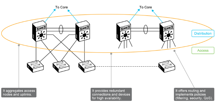
Acts as the demarcation point between the Access layer and Core layer:
-
Routing & Summarization: Performs route summarization toward the core, runs dynamic routing, and redistributes routing domains.
-
High Availability & Path Recovery: Dual-homed uplinks with Layer 3 Equal-Cost Multi-Pathing (ECMP) load sharing.
-
Gateway Redundancy: Uses First Hop Redundancy Protocols (FHRPs)—HSRP, VRRP, or GLBP—for default gateway failover.
-
Policy & Security Enforcement: Terminates access VLANs, applies Access Control Lists (ACLs), QoS, and traffic filtering.
C. Core Layer (The High-Speed Backbone)
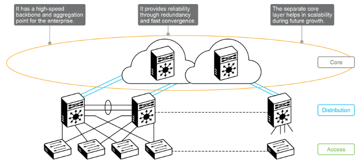
The simple, ultra-fast aggregation point designed for nonstop operations:
-
Core Mandates: Fast packet switching, near-instant recovery, and minimal control-plane configuration.
-
Design Rule: Never implement complex policy controls (ACLs, packet filtering) or connect end hosts/servers directly to core switches.
3. Scaling & Core Layer Necessity
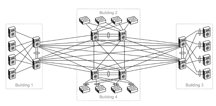
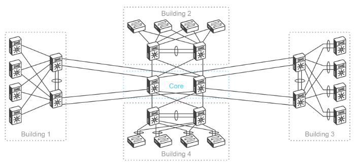
Connecting distribution blocks directly without a core creates a Full Mesh topology, causing routing complexity and excessive cabling.
(Where B is the number of building blocks, and N is the total number of nodes across all blocks, assuming 2 switches per block).
| Building Blocks (B) | Total Nodes (N) | Inter-Building Links Required (Full Mesh) |
| 2 Blocks | 4 Nodes | 4 Links |
| 3 Blocks | 6 Nodes | 12 Links |
| 4 Blocks | 8 Nodes | 24 Links |
Takeaway: Introducing a dedicated Layer 3 Core reduces connection complexity from quadratic growth to linear growth, keeping campus expansion modular and manageable.
|
|
|
4. Campus Design Scale Profiles
| Profile | Capacity / Scale | Design Characteristics |
| High-Density Large Campus | >15,000 wired & wireless users/devices | Dedicated L3 Core with 3+ Distribution blocks. Full hardware redundancy, NetFlow, and segmentation. |
| Medium-Density Campus | Hundreds of devices; <50 AP groups | Single Distribution block or Collapsed Core design. Standard business continuity features. |
| Small-Site Campus | Dozens of devices; <25 APs | Single access switch or switch stack. Cost-optimized with minimal features. |