
SD-Access - Data Plane (VXLAN)
1. Why SD-Access Uses VXLAN Instead of LISP for the Data Plane
Although LISP is used to manage the control plane, it has a key limitation that makes it unusable for the data plane on its own:
-
LISP Header Limitation: LISP only supports Layer 3 overlays because it discards the original Layer 2 Ethernet header. It cannot carry MAC addresses or Scalable Group Tags (SGTs).
-
VXLAN Capability: VXLAN supports both Layer 2 and Layer 3 overlays. It preserves the original Ethernet header and has reserved fields that can be extended to transport policy metadata (SGTs).
-
RFC 7348: Defines standard VXLAN as a method to overlay a Layer 2 network on top of a Layer 3 network.
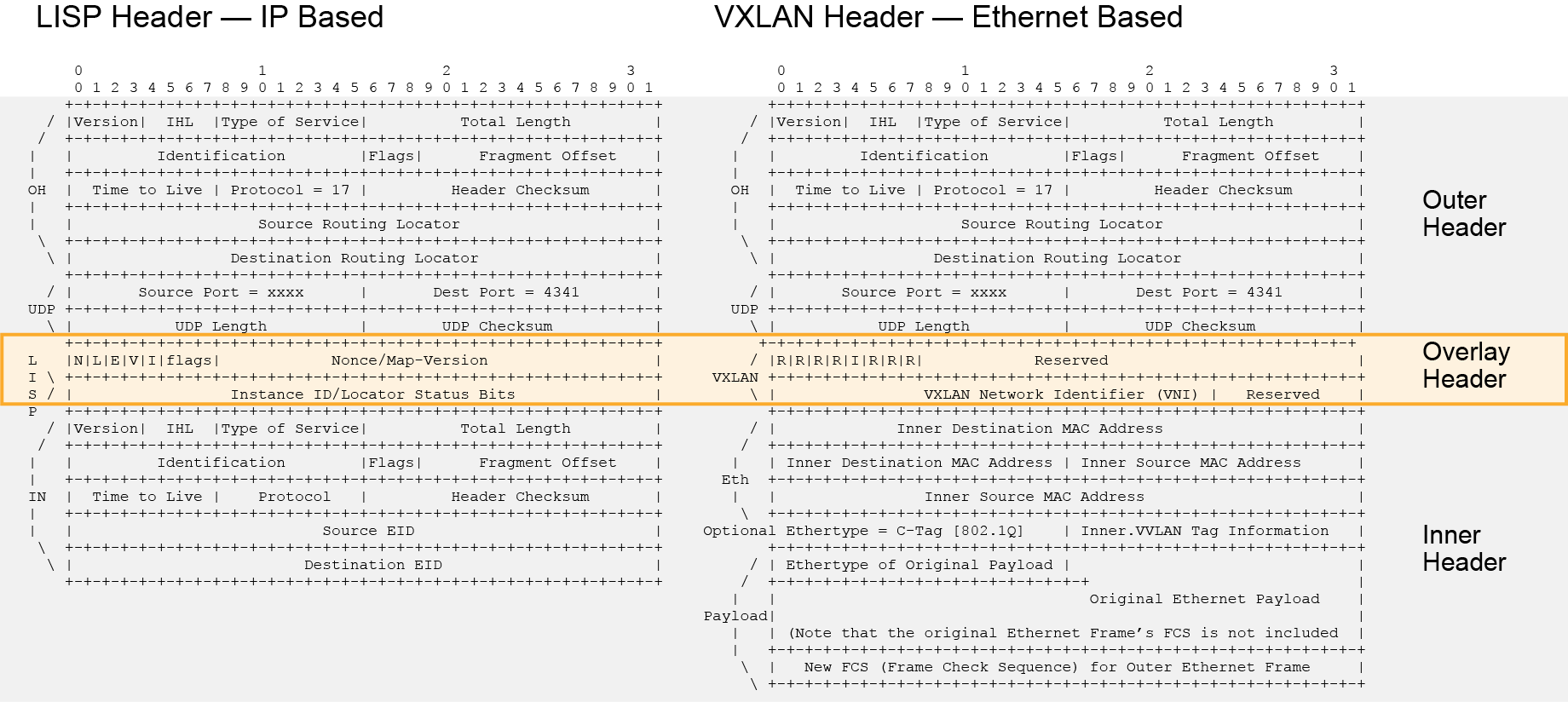
Functional Differences: LISP vs. VXLAN Header in SD-Access
| Capability | LISP Header | VXLAN Header (VXLAN-GPO) |
| SGT Tag Transport | Not supported (no field to carry SGTs). | Supported: Uses a dedicated 16-bit reserved field to propagate up to 64,000 SGTs. |
| Layer 3 Extension (VRF) | Supported. | Supported: Maps each VRF to a unique L3 Virtual Network Identifier (VNID). |
| Layer 2 Extension (VLAN) | Not supported (discards L2 header). | Supported: Maps each VLAN to a L2 Virtual Network Identifier (VNID). |
| Wireless Support | Not supported. | Supported: Runs a dedicated VXLAN tunnel between the Fabric AP and the Fabric Edge. |
2. VLAN Limitations vs. VXLAN Benefits
Traditional VLAN segmentation is highly restrictive in modern data center and campus networks:
VLAN Limitations
-
Limited Scalability: Supports a maximum of only 4,094 VLANs.
-
Inefficient Pathing: Relies on Spanning Tree Protocol (STP), which blocks redundant physical links, rendering up to half of the network links unusable.
-
Rigid Placement: Forces physical placement constraints on devices belonging to the same broadcast domain.
VXLAN Benefits
-
Massive Scalability: Supports up to 16 million coexistent segments, uniquely identified by a 24-bit VXLAN Network Identifier (VNID).
-
L3 Forwarding Efficiency: Bypasses STP by encapsulation over L3. Packets are routed using standard L3 routing, Equal-Cost Multi-Path (ECMP) routing, and link aggregation, utilizing all available physical paths.
-
Flexible Placement: Allows multitenant L2 segments to stretch across Layer 3 underlay boundaries seamlessly.
-
SDN Integration: Decoupling the overlay from the underlay allows SDN controllers to dynamically reprogram the network for modern cloud platforms.
Aclarated Note: Cisco OTV vs. VXLAN
Both technologies stretch L2 networks, but their target use cases differ:
Cisco OTV (Overlay Transport Virtualization): Designed to connect L2 networks between geographically separated data centers. It uses conservative protocols (like IS-IS and ARP caching) to aggressively minimize inter-site broadcast traffic.
VXLAN: Less conservative with broadcast traffic and is designed primarily to be used within a single data center or campus site.
3. The VXLAN-GPO Packet Encapsulation Format
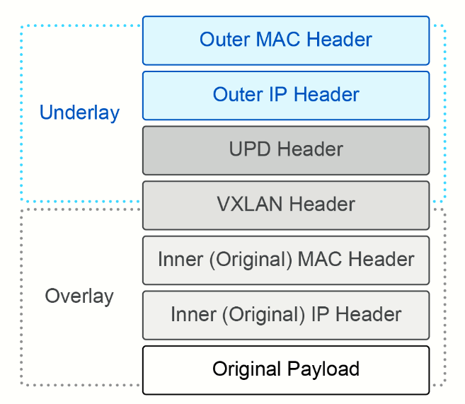
To support SD-Access, the fabric uses VXLAN-GPO (Group Policy Option), which replaces standard VXLAN reserved bits to insert policy tags. VXLAN Group Policy Extension (GPO) is the latest version of VXLAN. It adds special fields in the header to carry the virtual network IDs and the SGTs.
|
|
|
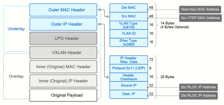
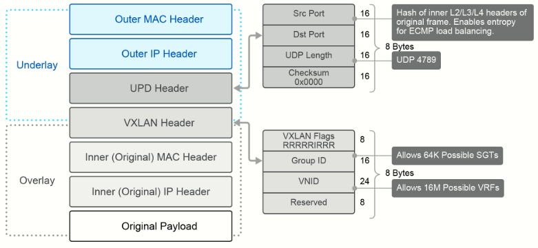
Full Encapsulation Breakdown (Layer-by-Layer)
I. Outer MAC Header (Underlay Link) — 14 Bytes (+4B if optional VLAN Tag is used)
-
Destination MAC: Next-Hop MAC Address.
-
Source MAC: Source VTEP (Virtual Tunnel Endpoint) MAC Address.
-
VLAN Type (optional): 0x8100.
-
VLAN ID (optional): Local VLAN identifier.
-
Ether Type: 0x0800 (IP).
II. Outer IP Header (Underlay Routing) — 20 Bytes
-
Protocol: 0x11 (UDP).
-
Source IP: Source RLOC IP Address.
-
Destination IP: Destination RLOC IP Address.
-
Header Checksum: Verifies outer IP header integrity.
III. UDP Header (Underlay Entropy) — 8 Bytes
-
Source Port: A dynamic 16-bit hash value calculated from the inner frame's L2/L3/L4 headers. This introduces entropy, allowing underlay routers to load-balance traffic across multiple ECMP paths and prevent link polarization.
-
Destination Port: Static UDP 4789 (the standard port designating the payload as VXLAN).
-
UDP Length: 16-bit length of the UDP packet.
-
UDP Checksum: 16-bit checksum (typically set to 0x0000).
IV. VXLAN-GPO Header (Fabric Virtualization & Policy) — 8 Bytes
-
VXLAN Flags (8 bits): Status and format flags (
RRRRRIRRorN|L|E|V|I|flags). -
Group ID / SGT (16 bits): Replaces 16 reserved bits of standard VXLAN. Propagates up to 64,000 unique Scalable Group Tags (SGTs) across the data plane to enforce group-based access control inside the virtualized network.
-
VXLAN Network Identifier / VNID (24 bits): Identifies the virtual segment. Maps directly to a VRF (for L3 isolation) or a VLAN (for L2 isolation), supporting up to 16 million distinct virtual networks.
-
Reserved (8 bits): Remaining unused space.
V. Inner Header & Payload (Original Packet)
-
Inner Destination MAC & Inner Source MAC: Original Layer 2 addresses.
-
Optional Ethertype: C-Tag (802.1Q) with inner VLAN tag information.
-
Inner IP Header: Original Source EID and Destination EID.
-
Original Payload: The actual data payload being transmitted.
-
Frame Check Sequence (FCS) Handling: The original Ethernet Frame's FCS is discarded during encapsulation. A brand-new FCS is computed and appended to the outer Ethernet frame.