Lab - Implement VRRP
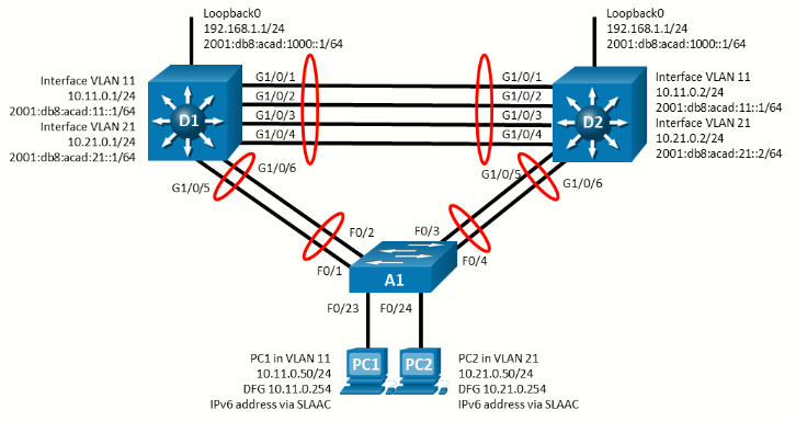
Topology
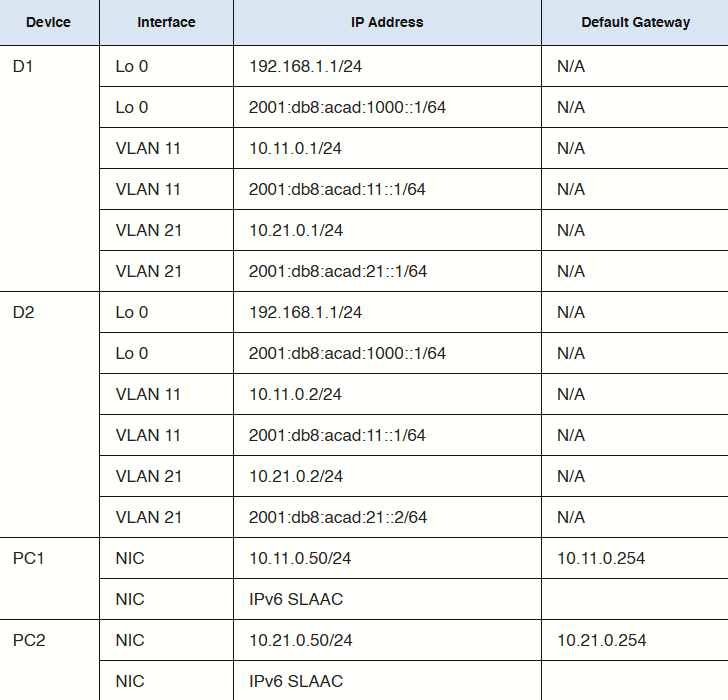
Addressing Table
Objectives
- Part 1: Build the Network and Configure Basic Device Settings and Interface Addressing
- Part 2: Configure and Observe VRRP for IPv4 and IPv6
- Part 3: Configure and Observe VRRP Object Tracking
Background / Scenario
The Virtual Router Redundancy Protocol (VRRP) is a standards-based alternative to HSRP and is defined in RFC 3768 (VRRP) and RFC 5798 (VRRPv3). The two technologies are similar but not compatible. HSRP elects an active and standby router to participate in the HSRP process, while VRRP elects a Master and Backup. Although referred to by different names, the operational concepts of the VRRP master and backup are similar to the HSRP active and standby respectively.
Both HSRP and VRRP operation requires the use of a virtual router IP address, but VRRP can use an address assigned to an interface on the device. In this case, the device automatically assumes the master role and ignores the priority value in its role election process. Recall that preemption in HSRP must be explicitly configured. VRRP uses preempt by default.
Note: This lab is an exercise in deploying and verifying VRRP and does not necessarily reflect networking best practices.
Note: The switches used with CCNP hands-on labs are Cisco 3650 with Cisco IOS XE release 16.9.4 (universalk9 image) and Cisco 2960 with IOS release 15.2 (lanbase image). Other routers and Cisco IOS versions can be used. Depending on the model and Cisco IOS version, the commands available and the output produced might vary from what is shown in the labs.
Note: Ensure that the switches have been erased and have no startup configurations. If using 3560s configure:
sdm prefer dual-ipv4-and-ipv6 routingRequired Resources - Sergio Jimenez's Version
- 2 Switches (Cisco 3550)
- 1 Switch (Cisco 2960CX)
- 2 PC (Choice of operating system with a terminal emulation program installed)
- Console cables to configure the Cisco IOS devices via the console ports
- Ethernet cables as shown in the topology
Instructions
Part 1: Build the Network and Configure Basic Device Settings and Interface Addressing
In Part 1, you will set up the network topology and configure basic settings and interface addressing.
Step 1: Cable the network as shown in the topology
Attach the devices as shown in the topology diagram, and cable as necessary.
Step 2: Configure basic settings for each switch.
Switch D1
hostname D1
ip routing
ipv6 unicast-routing
no ip domain lookup
banner motd # D1, Implement VRRP #
line con 0
 exec-timeout 0 0
 logging synchronous
 exit
line vty 0 4
 privilege level 15
 password cisco123
 exec-timeout 0 0
 logging synchronous
 login
 exit
interface range f0/1-6
 switchport trunk encapsulation dot1q
 switchport mode trunk
 no shutdown
 exit
interface range f0/1-4
 channel-group 12 mode active
 exit
interface range f0/5-6
 channel-group 1 mode active
 exit
vlan 11
 name FIRST_VLAN
 exit
vlan 21
 name SECOND_VLAN
 exit
interface vlan 11
 ip address 10.11.0.1 255.255.255.0
 ipv6 address fe80::d1:1 link-local
 ipv6 address 2001:db8:acad:11::1/64
 no shutdown
 exit
interface vlan 21
 ip address 10.21.0.1 255.255.255.0
 ipv6 address fe80::d1:2 link-local
 ipv6 address 2001:db8:acad:21::1/64
 no shutdown
 exit
interface loopback 0
 ip address 192.168.1.1 255.255.255.0
 ipv6 address fe80::d1:3 link-local
 ipv6 address 2001:db8:acad:1000::1/64
 no shutdown
 exit
Switch D2
hostname D2
ip routing
ipv6 unicast-routing
no ip domain lookup
banner motd # D2, Implement VRRP #
line con 0
 exec-timeout 0 0
 logging synchronous
 exit
line vty 0 4
 privilege level 15
 password cisco123
 exec-timeout 0 0
 logging synchronous
 login
 exit
interface range f0/1-6
 switchport trunk encapsulation dot1q
 switchport mode trunk
 no shutdown
 exit
interface range f0/1-4
 channel-group 12 mode active
 exit
interface range f0/5-6
 channel-group 2 mode active
 exit
vlan 11
 name FIRST_VLAN
 exit
vlan 21
 name SECOND_VLAN
 exit
interface vlan 11
 ip address 10.11.0.2 255.255.255.0
 ipv6 address fe80::d2:1 link-local
 ipv6 address 2001:db8:acad:11::2/64
 no shutdown
 exit
interface vlan 21
 ip address 10.21.0.2 255.255.255.0
 ipv6 address fe80::d2:2 link-local
 ipv6 address 2001:db8:acad:21::2/64
 no shutdown
 exit
interface loopback 0
 ip address 192.168.1.1 255.255.255.0
 ipv6 address fe80::d2:3 link-local
 ipv6 address 2001:db8:acad:1000::1/64
 no shutdown
 exit
Switch A1
hostname A1
banner motd # A1, Implement VRRP #
line con 0
 exec-timeout 0 0
 logging synchronous
 exit
line vty 0 4
 privilege level 15
 password cisco123
 exec-timeout 0 0
 logging synchronous
 login
 exit
interface range g0/1-4
 switchport mode trunk
 no shutdown
 exit
interface range g0/1-2
 channel-group 1 mode active
 exit
interface range g0/3-4
 channel-group 2 mode active
 exit
vlan 11
 name FIRST_VLAN
 exit
vlan 21
 name SECOND_VLAN
 exit
interface g0/9
 switchport mode access
 switchport access vlan 11
 spanning-tree portfast
 no shutdown
 exit
interface g0/10
 switchport mode access
 switchport access vlan 21
 spanning-tree portfast
 no shutdown
 exit
interface vlan 11
 ip address 10.11.0.3 255.255.255.0
 ipv6 address fe80::a1:1 link-local
 ipv6 address 2001:db8:acad:11::3/64
 no shutdown
 exit
ip default-gateway 10.11.0.254
Step 3: Configure the PCs for network connectivity
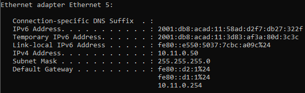
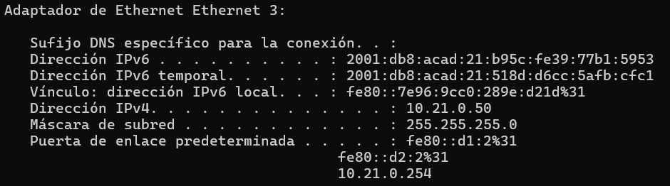
Configure PC1 and PC2 with the IPv4 address, subnet mask, and default gateway specified in the topology diagram. The IPv6 address and default gateway information for each PC will come from SLAAC.
|
|
|
Part 2: Configure and Observe VRRP for IPv4
On the 3560 VRRPv3 is not supported.
Like HSRP, VRRP provides redundancy in the network. Traffic can be load-balanced by assigning different gateway devices different priorities, spreading the load out amongst devices. Priority can be a value between 1 and 254. The default priority value is 100, and a higher priority value is preferable. Unlike HSRP, preemption is enabled by default in VRRP.
In this lab, the group numbers will be 11 and 21 for IPv4.
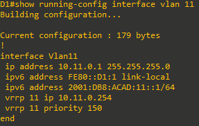
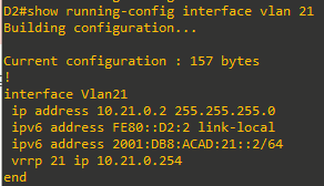
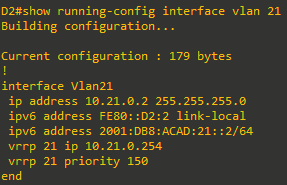
In the following configurations, the priority for VLAN 11 on D1 is set to 150, making it the master virtual router for VLAN 11. VLAN 21 has the default priority of 100 on D1, making D1 the backup virtual router for VLAN 21. D2 is configured to be the master virtual router for VLAN 21 with a priority of 150, and the backup virtual router for VLAN 11 with a default priority of 100.
Step 1: Configure VRRP on Switch D1
-
Configure vrrp group 11 on interface VLAN 11 with a vrrp IP address of 10.11.0.254 and a priority of 150
-
Configure vrrp group 21 on interface VLAN 21 with a vrrp IP address of 10.21.0.254.


Step 2: Verify VRRP is operational on Switch D1
-
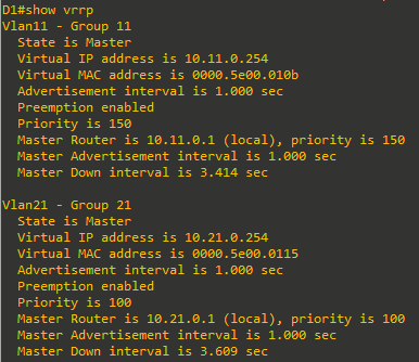
Verify that VRRP is active and operating on switch D1 with the
show vrrpcommand. Because D1 is the only switch configured for VRRP, it is the master on all groups.
-
You can also use the
show vrrp briefcommand to get a less verbose status.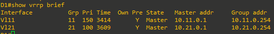
-
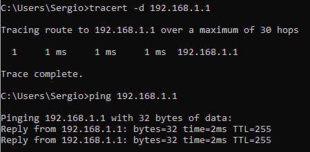
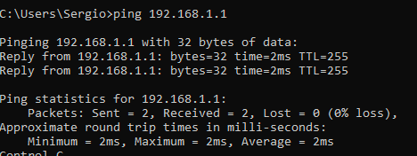
Interface Loopback0 on D1 and D2 represent a destination on the internet. From PC1 and PC2, ping the IPv4 address of interface Loopack0 on D1. A successful ping verifies that the gateway router is working.


Step 3: Configure VRRP on Switch D2
-
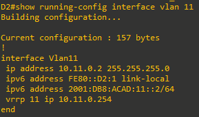
Configure vrrp group 11 on interface VLAN 11 with a vrrp IP address of 10.11.0.254.

- Configure vrrp group 21 on interface VLAN 21 with a vrrp IP address of 10.21.0.254 and a priority of 150.

Step 4: Verify VRRP is operational on Switch D2
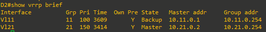
-
Verify that VRRP is active and operating on switch D2 with the
show vrrp briefcommand. Based on the configuration, D2 should be the master switch on interface VLAN 21 only.
-
Interface Loopback0 on D1 and D2 represent a destination on the internet. From PC1 and PC2, ping the IPv4 address of interface Loopack0 on D1. A successful ping verifies that the gateway router is working.

Step 5: Observe and validate VRRP operation
The whole point of VRRP is to help maintain gateway reachability in case of an outage. In this step, we will simulate an outage to show how VRRP achieves this objective.
- On PC1, start a continuous ping to 192.168.1.1
- On Switch D1, issue the
shutdowncommand on interface VLAN 11. Note that D2 takes over the active role, and there is very little traffic loss in the running pings.
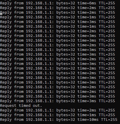
- On Switch D1, issue the
no shutdowncommand on interface VLAN 11. Note that D1 takes back over as the active router, and once again there is very little traffic loss experienced. - Stop the continuous ping running on PC1.

Part 3: Configure and Observe VRRP Object Tracking
VRRP can perform object tracking. This enables the priority of a virtual group router to be automatically adjusted, based on the status of the tracked entity. When a tracked entity becomes unavailable, the VRRP priority of the router is decreased. This might cause another router to take over as the master router for a group based on its higher priority value. When properly configured, the VRRP tracking feature ensures that a router with an unavailable key interface will relinquish the master router role.
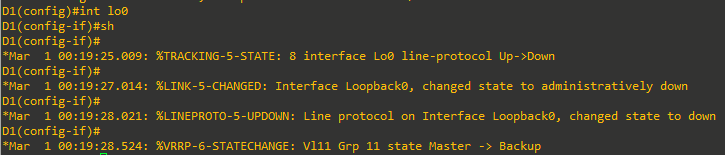
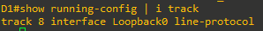
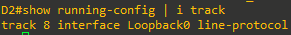
Step 1: Create a tracked object
Create an object on Switch D1 and D2 that tracks the line-protocol of interface Loopback 0.
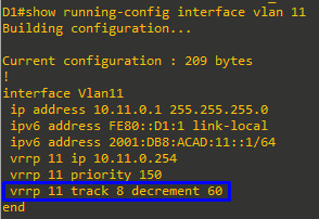
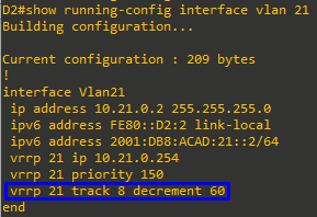
Step 2: Configure VRRP to track the object status
On D1, configure standby group 11 to track the status of track 4. On D2, configure standby group 21 to track the status of track 4. When the tracked object has failed, decrement the system priority by 60.
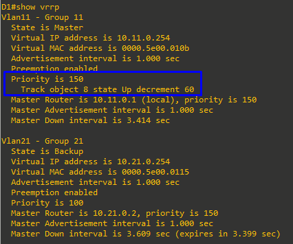
Step 3: Verify the VRRP configuration.
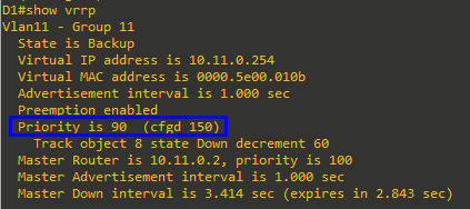
Issue the command show vrrp on Switch D1. This is the full version of the command, and in the output, you can see all the adjustments that have been made to this point.
Step 4: Verify VRRP complies with the configuration.
-
On D1, shutdown interface Loopback 0. Switch D2 should take over as master for group 11. Verify D1’s current priority value and D2’s status with the
show vrrp briefcommand.

-
Examine the priority information in detail in the output of the
show vrrpcommand.