Lab - Implement a GRE Tunnel
Topology
Addressing Table
| Device | Interface | IP Address | IPv6 Address | IPv6 Link Local |
| R1 | G0/0 | 10.1.2.1/24 |
2001:db8:acad:12::1/64 |
fe80::1:1 |
| Loopback0 | 192.168.1.1/24 |
2001:db8:acad:1::1/64 |
fe80::1:2 | |
| Loopback1 | 172.16.1.1/24 | 2001:db8:acad:1721::1/64 | fe80::1:3 | |
| R2 | G0/0 | 10.1.2.2/24 |
2001:db8:acad:12::2/64 |
fe80::2:1 |
| G0/1 | 10.2.3.2/24 | 2001:db8:acad:23::2/64 | fe80::2:2 | |
| R3 | G0/0 | 10.2.3.3/24 |
2001:db8:acad:23::3/64 |
fe80::3:1 |
| Loopback0 | 192.168.3.1/24 | 2001:db8:acad:3::1/64 | fe80::3:2 | |
| Loopback1 | 172.16.3.1/24 | 2001:db8:acad:1723::1/64 | fe80::3:3 |
Objectives
- Part 1: Configure basic settings for each device.
- Part 2: Configure and Verify GRE Tunnels with Static Routingç
- Part 3: Configure and Verify GRE Tunnels by Using a Routing Protocol
- Part 4: Examine the Recursive Routing Problem with GRE
Background / Scenario
Overlay networks are virtual networks that are built on top of existing physical or logical network infrastructures, which are known as underlay networks. By creating overlay networks, you can introduce additional flexibility and features to your network design without having to modify the underlying physical topology. This approach allows for easier implementation of new services, improved scalability, and better control over network traffic.
One key technology that enables the creation of overlay networks is Cisco’s Generic Routing Encapsulation (GRE) protocol. GRE is a tunneling protocol that allows you to encapsulate a wide variety of network layer protocols inside virtual point-to-point links, which are then transmitted across the underlay network. This means you can use GRE tunnels to connect remote sites, transport non-IP traffic, or create secure communication channels, regardless of the underlying network’s protocol.
GRE is highly flexible and supports both IPv4 and IPv6 as underlay networks, making it a versatile tool for many different networking scenarios. In this lab, you will learn how to deploy basic GRE tunnels over both IPv4 and IPv6 underlay networks.
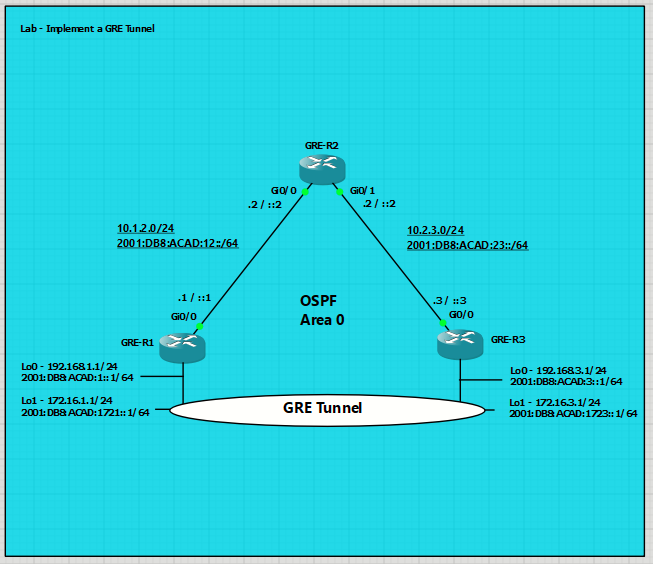
Topology Note: In the topology, the OSPF Area 0 network, encompassing R1, R2, R3, and their interconnected links, functions as the underlay network, providing the essential physical and logical IP connectivity. Despite its visual placement, the GRE Tunnel is the overlay network; it's a virtual connection built on top of this OSPF underlay, utilizing the underlay's routing capabilities to transport encapsulated traffic between R1 and R3.
Note: This lab is an exercise in configuring and verifying various implementations of GRE tunnels and does not reflect networking best practices.
Required Resources - Sergio Jimenez's Version
For this lab I am using GNS3 where I have deployed:
- 3 IOSv router
Instructions
Part 1: Configure basic settings for each device.
GRE-R1
hostname R1
no ip domain lookup
ipv6 unicast-routing
banner motd # R1, Implement a GRE Tunnel #
line con 0
exec-timeout 0 0
logging synchronous
exit
line vty 0 4
privilege level 15
password cisco123
exec-timeout 0 0
logging synchronous
login
exit
router ospf 4
router-id 1.1.1.4
exit
ipv6 router ospf 6
router-id 1.1.1.6
exit
interface g0/0
ip address 10.1.2.1 255.255.255.0
ipv6 address fe80::1:1 link-local
ipv6 address 2001:db8:acad:12::1/64
no shutdown
ip ospf 4 area 0
ipv6 ospf 6 area 0
exit
interface loopback 0
ip address 192.168.1.1 255.255.255.0
ipv6 address fe80::1:2 link-local
ipv6 address 2001:db8:acad:1::1/64
no shutdown
ip ospf 4 area 0
ipv6 ospf 6 area 0
exit
interface loopback 1
ip address 172.16.1.1 255.255.255.0
ipv6 address fe80::1:3 link-local
ipv6 address 2001:db8:acad:1721::1/64
no shutdown
exit
GRE-R2
hostname R2
no ip domain lookup
ipv6 unicast-routing
banner motd # R2, Implement a GRE Tunnel #
line con 0
exec-timeout 0 0
logging synchronous
exit
line vty 0 4
privilege level 15
password cisco123
exec-timeout 0 0
logging synchronous
login
exit
router ospf 4
router-id 2.2.2.4
exit
ipv6 router ospf 6
router-id 2.2.2.6
exit
interface g0/0
ip address 10.1.2.2 255.255.255.0
ipv6 address fe80::2:1 link-local
ipv6 address 2001:db8:acad:12::2/64
no shutdown
ip ospf 4 area 0
ipv6 ospf 6 area 0
exit
interface g0/1
ip address 10.2.3.2 255.255.255.0
ipv6 address fe80::2:2 link-local
ipv6 address 2001:db8:acad:23::2/64
no shutdown
ip ospf 4 area 0
ipv6 ospf 6 area 0
exit
GRE-R3
hostname R3
no ip domain lookup
ipv6 unicast-routing
banner motd # R3, Implement a GRE Tunnel #
line con 0
exec-timeout 0 0
logging synchronous
line vty 0 4
privilege level 15
password cisco123
exec-timeout 0 0
logging synchronous
login
router ospf 4
router-id 3.3.3.4
ipv6 router ospf 6
router-id 3.3.3.6
interface g0/0
ip address 10.2.3.3 255.255.255.0
ipv6 address fe80::3:1 link-local
ipv6 address 2001:db8:acad:23::3/64
no shutdown
ip ospf 4 area 0
ipv6 ospf 6 area 0
interface loopback 0
ip address 192.168.3.1 255.255.255.0
ipv6 address fe80::3:2 link-local
ipv6 address 2001:db8:acad:3::1/64
no shutdown
ip ospf 4 area 0
ipv6 ospf 6 area 0
interface loopback 1
ip address 172.16.3.1 255.255.255.0
ipv6 address fe80::3:3 link-local
ipv6 address 2001:db8:acad:1723::1/64
no shutdown
Part 2: Configure and Verify GRE Tunnels with Static Routing
In Part 2, you will configure and verify GRE tunnels between R1 and R3. You will use static routes for overlay reachability and dynamic routing for underlay reachability. You will create two tunnels: one for IPv4 and one for IPv6. GRE tunnels are highly flexible, with many implementation options beyond this lab.
Step 1: Verify reachability between R1 and R3.
- From R1, ping R3 interface Loopback 0 using IPv4. All pings should be successful.

- From R1, ping R3 interface Loopback 0 using IPv6. All pings should be successful.



Step 2: Create an IPv4-based GRE tunnel between R1 and R3.
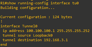
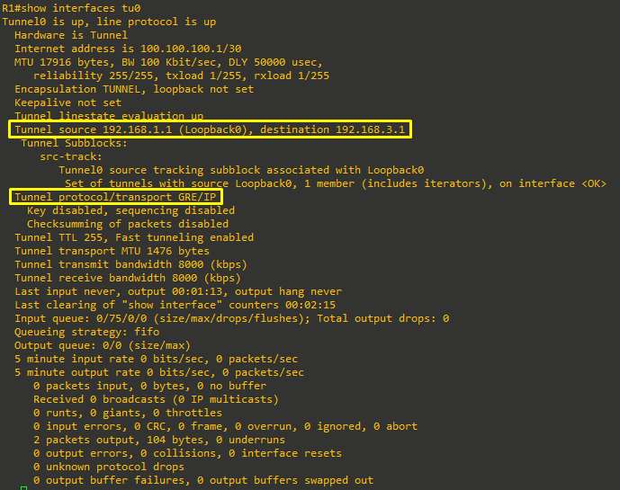
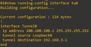
- On R1, create interface Tunnel 0, specifying the IP address 100.100.100.1/30, a tunnel source of Loopback0, and a tunnel destination of 192.168.3.1. This sets up the GRE overlay endpoint on R1. The configured IPv4 address identifies the tunnel interface, the source uses R1’s Loopback0, and the destination points to R3’s underlay address.
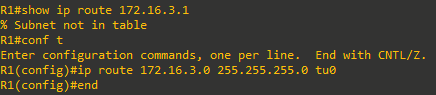
- On R1, create a static route to 172.16.3.0/24 via interface Tunnel 0. This directs overlay traffic for the 172.16.3.0/24 network through the GRE tunnel, ensuring reachability to R3’s LAN via the overlay.
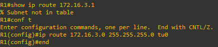
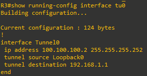
- On R3, create interface Tunnel 0, specifying the IP address 100.100.100.2/30, a tunnel source of Loopback0, and a tunnel destination of 192.168.1.1. This mirrors the GRE overlay configuration on R3. The IPv4 address assigns the peer tunnel interface, using R3’s Loopback0 as the source and R1’s underlay address as the destination.
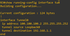
- On R3, create a static route to 172.16.1.0/24 via interface Tunnel 0. This sends overlay traffic for the 172.16.1.0/24 network through the GRE tunnel, providing reachability to R1’s LAN via the overlay

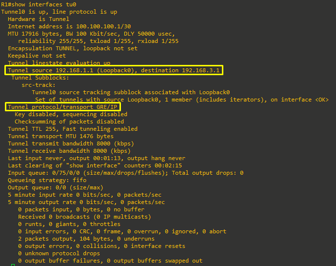
- On R1, issue the command show interface tunnel 0 and examine the output.
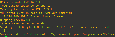
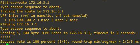
- From R1, ping 172.16.3.1. The pings should be successful

Step 3: Create an IPv6-based GRE tunnel between R1 and R3
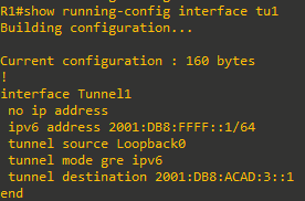
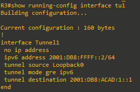
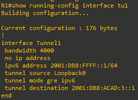
- On R1, create interface Tunnel 1, specifying the IPv6 address 2001:db8:ffff::1/64, a tunnel source of Loopback0, a tunnel destination of 2001:db8:acad:3::1, and the tunnel mode GRE IPv6.
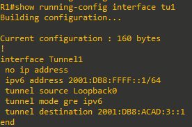
- On R1, create a static route to 2001:db8:acad:1723::/64 via interface Tunnel 1.

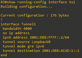
- On R3, create interface Tunnel 1, specifying the IPv6 address 1002:db8:ffff::2/64, a tunnel source of Loopback0, and a tunnel destination of 2001:db8:acad:1::1.
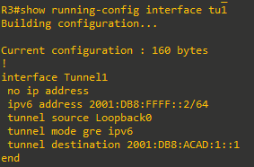
- On R3, create a static route to 2001:db8:acad:1721::/64 via interface Tunnel 1.

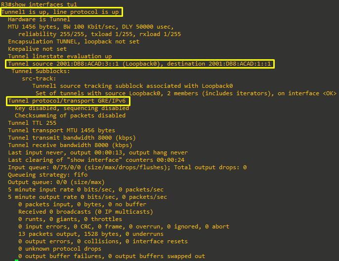
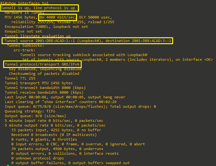
- On R1, issue the command show interface tunnel 1 and examine the output
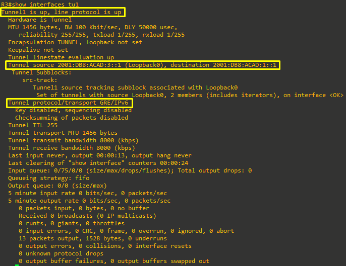
- From R1, ping 2001:db8:acad:1723::1. The pings should be successful.




Part 3: Configure and verify GRE Tunnels with Dynamic Routing
In Part 3, you will rebuild GRE tunnels between R1 and R3 using dynamic routing over the overlay and static
routing in the underlay. The goal is to:
- Use static routes in the underlay so each router can reach the other’s loopback addresses (tunnel endpoints).
- Run OSPF across the GRE tunnels to dynamically learn and advertise the LAN prefixes behind R1 and R3.
- Configure two tunnels: one for IPv4 and one for IPv6, and verify neighbor formation, routing table entries, and end-to-end reachability.
Step 1: Remove the Tunnel 0 and Tunnel 1 interfaces on R1 and R3.
Removing the existing tunnel interfaces ensures there are no residual configurations that could interfere with the new dynamic routing design. This clears prior tunnel states and any overlay-specific settings.
Issue the command no interface tunnel 0 and no interface tunnel 1 on R1 and R3.
Step 2: Replace the OSPF configuration on R1, R2, and R3 with static routing.
This step prepares the underlay so that each device can reach the other devices’ loopbacks using static routes. The GRE tunnels will then form over these reachable endpoints, and OSPF will operate across the overlay.
- On R1, R2, and R3, remove OSPF with the no router ospf 4 and no ipv6 router ospf 6 commands.
This cleanly removes existing OSPFv2 and OSPFv3 processes to prevent unintended adjacencies or learned routes while you build the new overlay. - On R1 and R3, create IPv4 and IPv6 static default routes that point to R2.

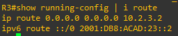
- On R2, create IPv4 and IPv6 static routes that point to R1 and R3 loopback 0 networks.

- Verify that R1 can reach Loopback 0 on R3 with pings using a source address of the R1 Loopback 0 address



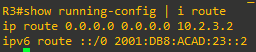



Step 3: Create an IPv4-based GRE tunnel between R1 and R3.
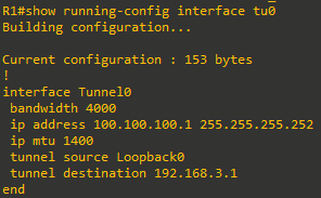
This establishes the IPv4 GRE overlay for OSPFv2. The bandwidth and MTU settings help ensure accurate routing metrics and avoid fragmentation of encapsulated packets.
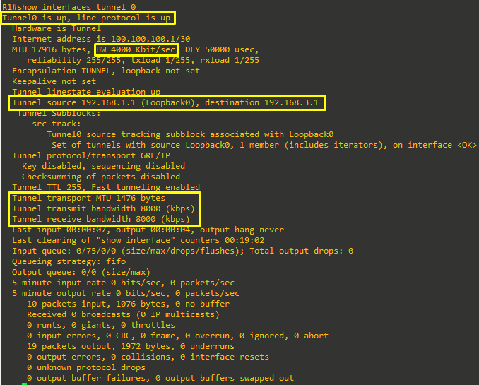
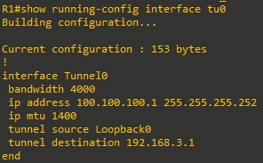
- On R1, create interface Tunnel 0, specifying the IP address 100.100.100.1/30, bandwidth of 4000 kbps, a tunnel source of Loopback0, and a tunnel destination of 192.168.3.1.
- The Tunnel0 IP address defines the overlay adjacency point for OSPF.
- The bandwidth value informs routing and QoS features; it is not a hard rate limit.
- The ip mtu 1400 accommodates GRE/IP overhead to reduce fragmentation risks on a 1500-byte underlay.
- The source and destination identify the underlay endpoints used for GRE encapsulation.
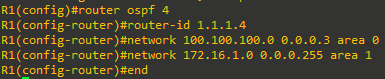
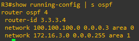
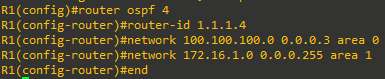
- On R1, configure OSPFv2 process-id 4 with router-id 1.1.1.4, and use network statements or interface configuration commands to include interface Tunnel 0 in Area 0 and interface Loopback 1 in Area 1. This will form the OSPF adjacency across the tunnel (Area 0) and advertises the Loopback1 prefix from a separate area (Area 1).
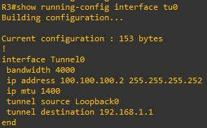
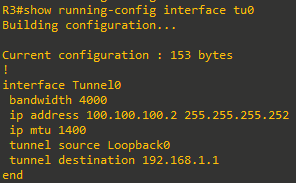
- On R3, create interface Tunnel 0, specifying the IP address 100.100.100.2/30, bandwidth of 4000 kbps, a tunnel source of Loopback0, and a tunnel destination of 192.168.1.1. This mirrors the tunnel configuration on R1 so that the overlay is point-to-point between the two tunnel interface addresses.
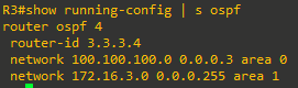
- On R3, configure OSPFv2 process-id 4 with router-id 3.3.3.4, and use network statements or interface configuration commands to include interface Tunnel 0 in Area 0 and interface Loopback 1 in Area 1. You should see an informational message that R3 has established full adjacency with R1.
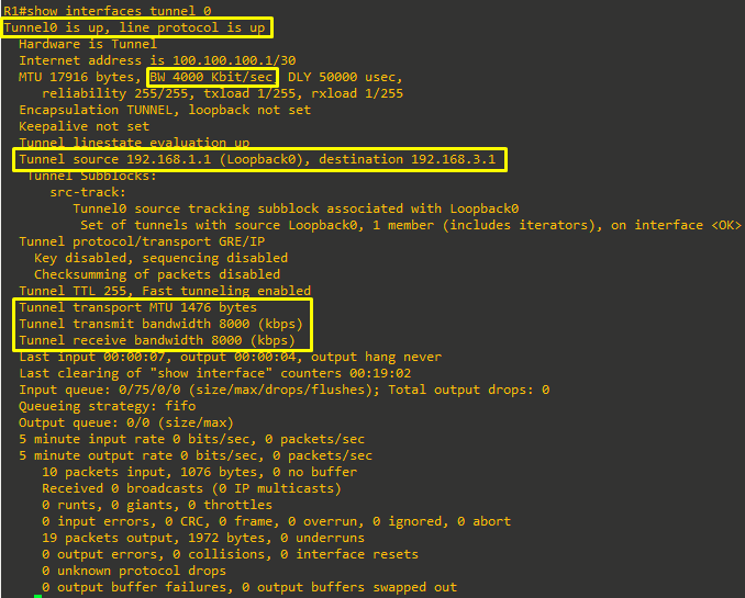
- On R1, issue the command show interface tunnel 0 and examine the output.
- On R1, issue the command show ip route ospf and verify that 172.16.3.0/24 appears in the routing table as an OSPF route.

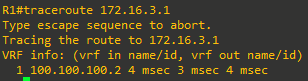
- From R1, ping 172.16.3.1. The pings should be successful.

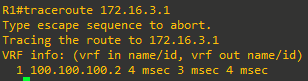
Step 4: Create an IPv6-based GRE tunnel between R1 and R3.
- On R1, create interface Tunnel 1, specifying the IPv6 address 2001:db8:ffff::1/64, bandwidth of 4000kbps, a tunnel source of Loopback0, and a tunnel destination of 2001:db8:acad:3::1.
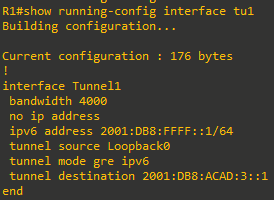
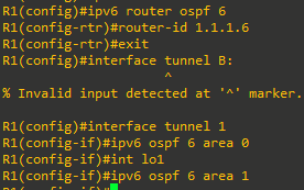
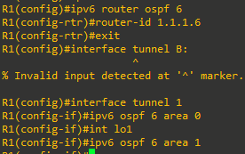
- On R1, configure OSPFv3 process-id 6 with router-id 1.1.1.6, and interface configuration commands to include interface Tunnel 0 in Area 0 and interface Loopback 1 in Area 1.
- On R3, create interface Tunnel 1, specifying the IPv6 address 1002:db8:ffff::2/64, bandwidth of 4000kbps, a tunnel source of Loopback0, and a tunnel destination of 2001:db8:acad:1::1.
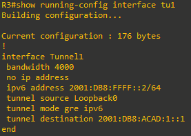
- On R3, configure OSPFv3 process-id 6 with router-id 3.3.3.6, and use network statements or interface configuration commands to include interface Tunnel 0 in Area 0 and interface Loopback 1 in Area 1.

- On R1, issue the command show interface tunnel 1 and examine the output.
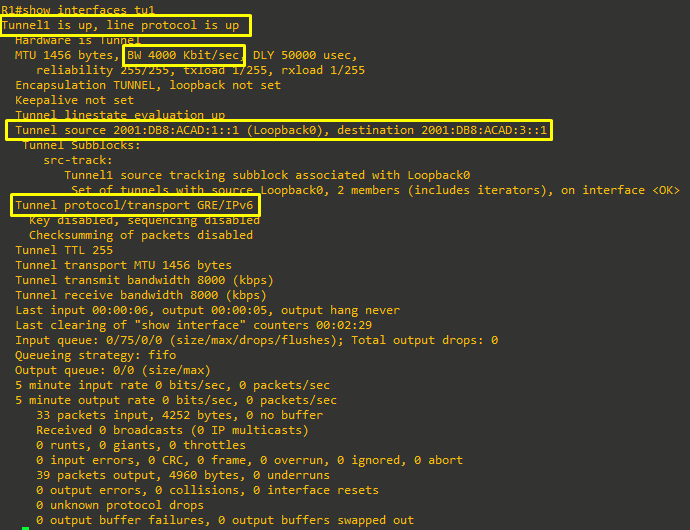
- On R1, issue the command show ipv6 route ospf and verify that 2001:db8:acad:1723::/64 appears in the routing table as an OSPF route.

- From R1, ping 2001:db8:acad:1723::1. The pings should be successful.




Part 4: Examine the Recursive Routing Problem with GRE
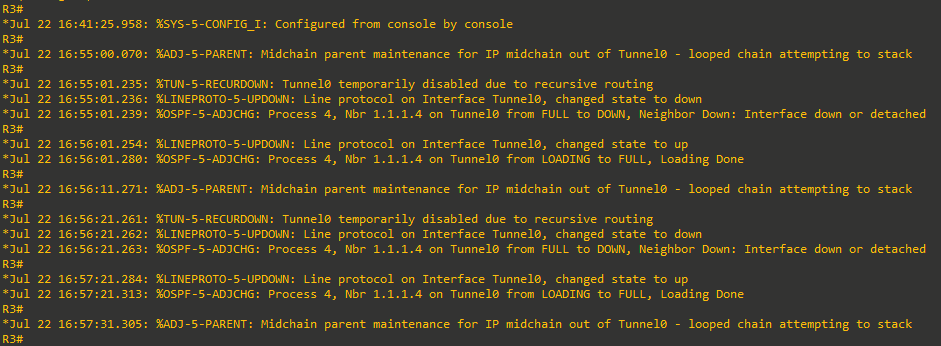
Recursive routing occurs when a router chooses an overlay interface (the GRE tunnel) to reach the underlay next hop that the tunnel itself depends on. In other words, the router decides that the best path to the tunnel destination is via the tunnel. This creates a forwarding loop and causes the overlay to fail. In this part, you will intentionally trigger the issue to observe its symptoms and then correct the configuration to restore stability.
- Goal: Understand how advertising underlay prefixes into the overlay can cause recursion and how to avoid it.
- Symptom: OSPF adjacencies over the tunnel flap, and the platform logs a recursive routing error for the tunnel.
- Fix: Keep tunnel endpoint (underlay) reachability out of the overlay routing domain; use static routes or carefully filtered dynamic routing for the underlay
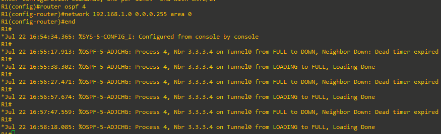
- To demonstrate how easily this could occur, add network 192.168.1.0 to the OSPF configuration of R1.

After the dead timer expires, the OSPF adjacency over Tunnel0 begins to flap because the control-plane hellos and data-plane traffic intermittently lose a valid underlay path when the route to the tunnel destination points back into the tunnel. The “Dead timer expired” message indicates OSPF stopped receiving hellos, consistent with a transient forwarding loop.
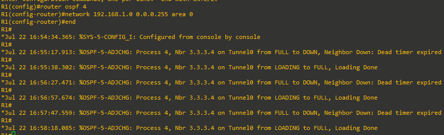
- R1 shows that the dead timer expires and then the adjacency tries to reset. Now look at what is being logged at R3.
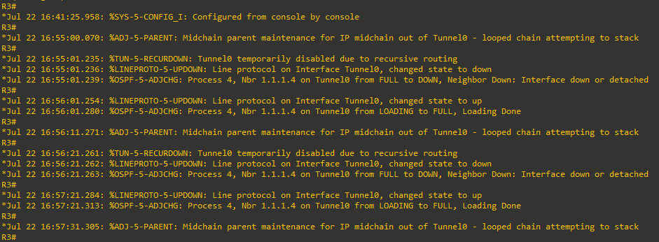
- As you can see, R3 recognizes the issue and even tells you there is a recursive routing problem. Fix this by removing the network statement on R1 and the tunnel will come back up.