
Lab - Implement Single-Area OSPFv2
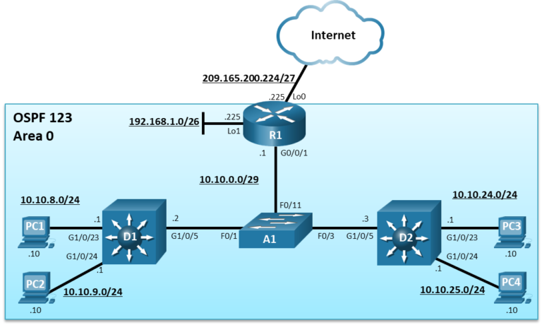
Topology
Addressing Table
| Device | Interface | IPv4 Address |
|---|---|---|
| R1 | G0/0/1 | 10.10.0.1/29 |
| Loopback0 | 209.165.200.225/27 | |
| Loopback1 | 192.168.1.1/26 | |
| D1 | G1/0/5 | 10.10.0.2/29 |
| G1/0/23 | 10.10.8.1/24 | |
| G1/0/24 | 10.10.9.1/24 | |
| D2 | G1/0/5 | 10.10.0.3/29 |
| G1/0/23 | 10.10.24.1/24 | |
| G1/0/24 | 10.10.25.1/24 | |
| PC1 | NIC | 10.10.8.10/24 |
| PC2 | NIC | 10.10.9.10/24 |
| PC3 | NIC | 10.10.24.10/24 |
| PC4 | NIC | 10.10.25.10/24 |
Objectives
- Part 1: Build the Network and Configure Basic Device Settings and Interface Addressing
- Part 2: Configure and Verify Single Area OSPF for IPv4 on R1, D1, and D2
- Part 3: Configure Default Route Propagation on R1 and Verify the Propagation
- Part 4: Implement OSPF Network Optimizing Features
- Part 5: DR and BDR Placement
Background / Scenario
In this lab, you will configure single-area OSPF version 2 for IPv4 on a multiaccess Ethernet LAN. This lab was specifically designed to use two Layer 3 switches instead of three routers to highlight how a Layer 3 switch can also be used to provide routing services.
Note: This lab is an exercise in developing, deploying, and verifying how OSPF operates and does not reflect networking best practices.
Note: The router used with CCNP hands-on labs is a Cisco 4221 and the two Layer 3 switches are Catalyst 3560 switches. Other Layer 3 switches and Cisco IOS versions can be used. Depending on the model and Cisco IOS version, the commands available and the output produced might vary from what is shown in the labs.
Note: Make sure that the switches have been erased and have no startup configurations
Required Resources - Sergio Jimenez's Version
- 2 Switches (Cisco 3560)
- 1 Switch (Cisco 2960)
- 1 Router (Cisco 2621)
- 1 PC (with 4 USB-to-Ethernet adapters)
- Console cables to configure the Cisco IOS devices via the console ports
- Ethernet cables as shown in the topology
Instructions
Part 1: Build the Network and Configure Basic Device Settings and Interface Addressing
In Part 1, you will set up the network topology and configure basic settings and interface addressing on the router and Layer 3 switches.
The Layer 2 switch should only have a default configuration.
Step 1: Cable the network as shown in the topology
Attach the devices as shown in the topology diagram, and cable as necessary.
Step 2: Configure basic settings for the router and the two Layer 3 switches.
- Console into each router and Layer 3 switch, enter global configuration mode, and apply the basic settings and interface addressing using the following startup configurations for each device.
Router R1
hostname R1
no ip domain lookup
line con 0
 logging sync
 exec-time 0 0
 exit
interface Loopback0
 ip address 209.165.200.225 255.255.255.224
 no shut
 exit
interface Loopback1
 ip address 192.168.1.1 255.255.255.192
 no shut
 exit
interface fa0/0
 ip address 10.10.0.1 255.255.255.248
 no shut
 exit
Switch D1
hostname D1
no ip domain lookup
line con 0
 logging sync
 exec-time 0 0
 exit
interface fa0/5
 no switchport
 ip address 10.10.0.2 255.255.255.248
 no shut
 exit
interface fa0/1
 no switchport
 ip address 10.10.8.1 255.255.255.0
 no shut
 exit
interface fa0/2
 no switchport
 ip address 10.10.9.1 255.255.255.0
 no shut
 exit
Switch D2
hostname D2 no ip domain lookup line con 0 logging sync exec-time 0 0 exit interface fa0/5 no switchport ip address 10.10.0.3 255.255.255.248 no shut exit interface fa0/1 no switchport ip address 10.10.24.1 255.255.255.0 no shut exit interface fa0/2 no switchport ip address 10.10.25.1 255.255.255.0 no shut exit -
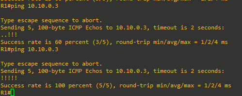
Verify direct connectivity between the highlighted IP addresses of R1, D1, and D2.

Part 2: Configure Single-Area OSPFv2
In this part, you will implement single-area OSPF on a multiaccess Ethernet network.
OSPF can be enabled using the traditional network router config command and wildcard mask. The wildcard mask enables the configuration to be as specific or vague as necessary. For example:
- network ip-address 0.0.0 area area-id – Configuring the network statement with an IP address explicitly enables OSPF on that interface.
- network network wildcard-mask area area-id – The wildcard mask can explicitly match a subnet, or it can be less specific to match several subnets as required.
- network 0.0.0.0 255.255.255.255 area area-id – This is the vaguest method as the 0.0.0.0 network with 255.255.255.255 wildcard mask matches all enabled interfaces.
An alternate method to using the network router configuration command is to use the interface specific method. Instead of the network statement, an interface is enabled for OSPF using the ip ospf process-id area area-id interface configuration command. Although simpler to use, the disadvantage is that the configuration is not centralized and increases in complexity as the number of interfaces on the routers increases.
Note: There is a newer method to configure OSPF using address families. Address families are covered in OSPFv3 and in CCNP Enterprise: Advanced Routing.
Step 1: Implement OSPF on D1 using Explicit IP addresses.
D1 will advertise its OSPF networks using the OSPF network ip-address 0.0.0.0 area area-id command method and quad-zero wildcard mask. This enables OSPF for Area 0 only on the interfaces that explicitly match the IP addresses configured.
- Layer 3 switches are not enabled to perform routing by default. Therefore, routing must be enabled using the
ip routingglobal configuration command.
D1(config)# ip routing -
Next, enter the OSPF router configuration mode using process ID 123. When using the quad-zero method, it is not necessary to calculate the actual wildcard mask. You simply advertise the IP address of the interface with a quad-zero wildcard mask and OSPF will advertise using the subnet mask of the interface. Configure OSPF to advertise the network address of the F0/5 interface (i.e., 10.10.0.2) with the quad-zero mask. Enable OSPF also on the F0/1 and F0/2 interfaces using a quad-zero mask.
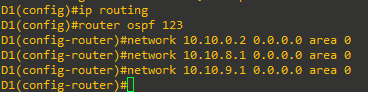
These networks are now being advertised to other OSPF routers. -
Verify the OSPF configuration on D1 using the show ip protocols command.
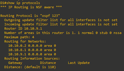
The OSPF router ID chosen was the highest active IPv4 address configured on D1. The Routing for Networks section in the output above confirms that the configured statements are accurately advertising the D1 networks.


Step 2: Implement OSPF on D2 using Wildcard Masks
D2 will advertise its OSPF networks using the network router configuration command and wildcard masks.
-
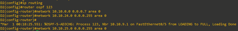
Like D1, D2 must be enabled for routing using the
ip routingglobal configuration command.D2(config)# ip routing -
Next, enter the OSPF router configuration mode using process ID 123. Note that process IDs are only locally significant. Therefore, the process ID of other OSPF routers do not need to match. However, using the same process ID makes it simpler to remember and reduces potential configuration mistakes. Configure D2 to advertise the F0/5 /29 interface in OSPF area 0. The wildcard mask can be calculated using by deducting the subnet mask (i.e., /29 = 255.255.255.248) from 255.255.255.255, resulting in a wildcard mask of 0.0.0.7. Next, configure D2 to advertise the two /24 networks in OSPF area 0. This can be accomplished using two
networkstatements with specific wildcard mask for each subnet.
Notice the informational message confirming that D2 has established a neighbor relationship with D1 (i.e., 10.10.9.1). This message appears right after entering the first network command.
Note: The two LAN networks could also be enabled using the
network 10.10.24.0 0.0.254.255statement instead.
There are no informational messages this time because these LAN interfaces are not connected to other OSPF-enabled routers. However, these networks are now being advertised to other OSPF routers.
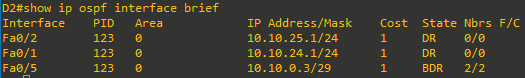
- Verify the OSPF configuration on D2 using the
show ip protocolscommand
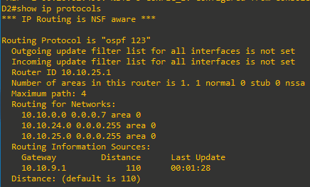
Again, the OSPF router ID chosen was the highest active IPv4 address configured on D2. The Routing for Networks section confirms that the configured statements are accurately advertising the D2 networks. We now also have another routing information source, 10.10.9.1 (i.e., D1).

Step 3: Implement OSPF on R1 using the Interface Specific method
R1 will use the OSPF interface specific method to advertise the Lo1 interface and the F0/0 interface. Interface Lo0 will be advertised in Part 3. The interface specific method is simple because there is no need to enter network statements or calculate wildcard masks. You simply enter the ip ospf process-id area area-id interface configuration command on an interface.
Note: Alternatively, the network 0.0.0.0 255.255.255.255 area 0 router configuration command would be simpler. However, it would enable OSPF on all interfaces including the Lo0 interface that will be advertised in Part 3.
-
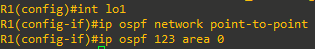
The loopback interface on R1 is only configured to simulate another network for OSPF to advertise. However, the default behavior of OSPF for loopback interfaces is to advertise a 32-bit host route. To ensure that the /26 network is advertised, the
ip ospf network point-to-pointinterface command must be configured on the loopback 1 interface. Change the network type on the loopback interfaces so that they are advertised with the correct subnet. Next enable the loopback interface for OSPF using theip ospf 123 area 0command as shown.
- Enter interface F0/0 and enable it for OSPF.

Notice how the informational messages are confirming that neighbor adjacencies have been established with D1 (i.e., 10.10.9.1) and D2 (i.e., 10.10.25.1).
-
Verify the OSPF configuration on R1 using the
show ip protocolscommand.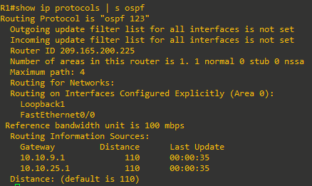
Again, the router ID chosen is the highest active IPv4 loopback address configured on R1. The Routing for Networks section confirms that routing was explicitly configured on the interfaces. It also displays a new routing source; 10.10.25.1.


Step 4: Assign Router IDs on R1, D1, and D2.
The OSPF router ID is dynamically assigned in order of preference:
- Manually configured using the
router-id router-idrouter configuration command. - If it is not manually assigned, then the highest enabled loopback IP address is used as the router ID.
- If there are no loopback interfaces configured, then the highest IP address of any active physical interfaces in the up state becomes the RID when the OSPF process initializes.
It is best to assign a static OSPF router ID for troubleshooting purposes.
To force an existing OSPF network to use the new router IP, the OSPF process must be reset using the clear ip ospf process privileged EXEC command.
-
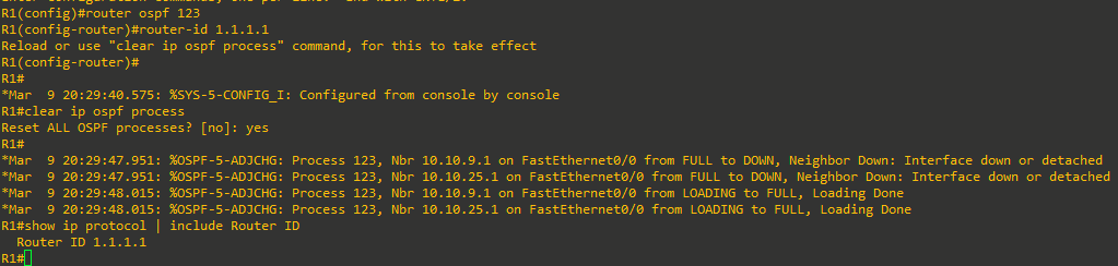
Assign R1 the router ID 1.1.1.1 as shown. Next clear the OSPF process as shown. Confirm that R1 is now using the new router ID as shown.

-
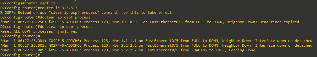
Repeat the process on D1 and D2. Use router ID 2.2.2.2 for D1 and 3.3.3.3 for D2. Also confirm that D1 and D2 are using the new router ID.
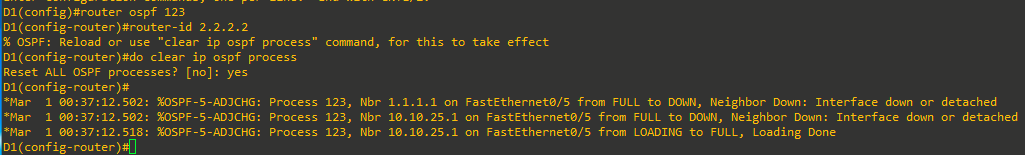


Step 5: Verify OSPF settings on R1, D1, and D2
It is imperative to know how to validate that OSPF is operating as configured. The show running-config command only displays the initial OSPF configuration. It does not validate the operation and functionality of OSPF.
Along with the show ip protocols command, there are several other useful OSPF-related show commands to verify that OSPF is operating as expected.
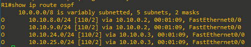
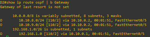
- The
show ip route ospfprivileged EXEC command is used to verify the operation of OSPF. The command displays OSPF routes learned with an O, the administrative distance, the assigned metric, the next-hop IP address, and the local exit interface to reach the network.

-
Use the
show ip ospf interface [brief]command to verify which interfaces are enabled for OSPF, process ID, Area ID, and state. A missing interface could be the result of an incorrect network statement, IP addressing problem, or a disabled interface.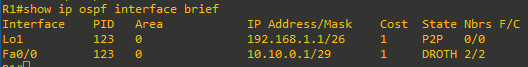
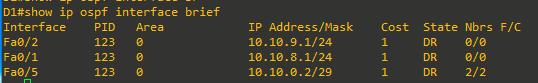
Note: Omitting the “brief” keyword displays detailed information about the OSPF enabled interfaces.
This State field defines the state of the link and can be:- DR – This is the Designated Router on the multiaccess network (i.e., Ethernet) to which this interface is connected. The DR establishes OSPF adjacencies with all other routers on the network.
- BDR – This is the Backup Designated Router on the multiaccess network to which this interface is connected. Like the DR, the BDR establishes adjacencies with all other routers on the broadcast network.
- DROTH – This is a DROTHER. It is neither the DR nor the BDR on the multiaccess network. All non-DRs and BDRs on the broadcast network would be DROTHERs and establish adjacencies only with the DR and the BDR.
- P2P – This is an OSPF point-to-point interface and does not require a DR or BDR. In this state, the interface is fully functional and starts exchanging hello packets with all of its neighbors.
-
Use the
show ip ospf neighbor [detail]command to verify which OSPF neighbor your device has established adjacencies with, the state, the next-hop IP address, and the exit interface to use. A neighbor may not be appearing include RIDs that are not unique, interconnecting interfaces that are not on a common subnet, MTU values that do not match, Area ID that is not correct, Hello and dead interval timers that do not match, or authentication type / credentials that do not match. The following output confirms that our devices have correctly established adjacencies. The output for R1 is shown below. Repeat the command for D1 and D2.

-
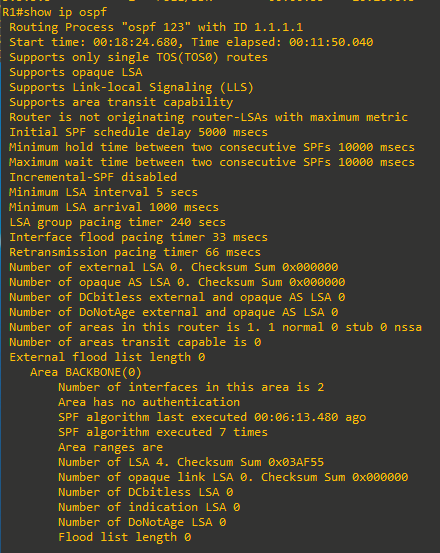
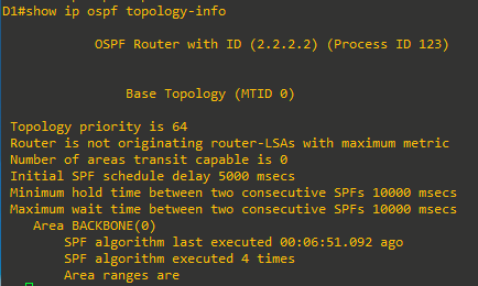
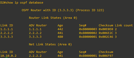
Other OSPF validation commands include the
show ip ospf,show ip ospf topology-info,show ip ospf databasecommands. Use these commands now and identify what types of information they generate which may be useful to know when troubleshooting a network.


Part 3: Configure and Verify the Advertising of a Default Route
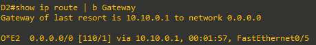
In this part, you will configure a default static route to the internet on R1. R1 will then propagate the default route to other OSPF routers as an external Type 2 OSPF route (i.e., O*E2).
Propagating a default is the most efficient method to provide a consistent default gateway to all OSPF- enabled devices.
Step 1: Configure default route advertisement on R1
-
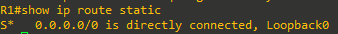
R1 will be the gateway of last resort for the OSPF internetwork. In our sample topology, the internet is simulated using the Lo0 interface. Configure a static default route out of the Lo0 interface on R1.
R1(config)# ip route 0.0.0.0 0.0.0.0 lo0
%Default route without gateway, if not a point-to-point interface, may impact performance
Note: Disregard the informational message. In a production environment, a valid physical interface would be used to provide default gateway services.
-
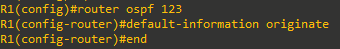
Enter OSPF router configuration mode and use the
default-information originate [always] [metric metric-value] [metric-type type-value]command to enable default route propagation. The always keyword advertises a default route even if a static default route does not exist while the route metric and metric type can be changed. R1 is configured to propagate the default route.
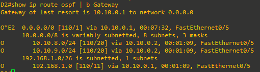
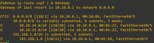
Step 2: Verify the default route advertisement
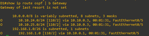
-
Verify the routing table on R1 and verify the routing table on D1 and D2.


Part 4: Implement OSPF Network Optimizing Features
In this part, you will configure OSPF optimizing features including:
- Passive interfaces
- Link costs
- Reference bandwidth
- Hello and Dead interval timers
Step 1: Configure passive interfaces on R1, D1 and D2.
A passive interface does not send out OSPF messages or process any received OSPF packets. However, the passive interface network segment is still added to the link state database (LSDB) and advertised out of non-passive interfaces. For security reasons, LAN interfaces which are not connected to other OSPF routers should be passive.
There are two approaches to identify passive interfaces.
- Use the
passive-interface interface-idrouter configuration command to make an interface passive. This is a good approach to use when there are only a few interfaces to make passive. - Use the
passive-interface defaultrouter config command to make all interfaces passive, and then make some interfaces not passive using theno passive-interface interface-idcommand. This is a good approach to use when there are many interfaces to make passive, but only a few interfaces that should not be passive.
-
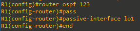
R1 only needs the Lo1 interface to be passive. The first approach is used to make the Loopback 1 interface passive. Enter OSPF router configuration mode and make the Lo1 interface passive as shown.
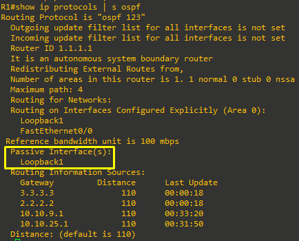
- Verify which interfaces are passive using the
show ip protocolscommand.

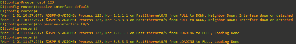
- A Layer 3 switch can potentially have many interfaces that should be passive. For example, assume that D1 and D2 only require their F0/5 interface to not be passive. However, all other interfaces should be passive. Using the first approach would be very time-consuming. For this reason, the second approach will be used. All active interfaces will be rendered passive and only interface F0/5 will be re-enabled.

Notice the information messages stating that the OSPF adjacency with R1 and D2 transitioned to the DOWN state. Disabling the passive feature on interface F0/5 re-enabled the OSPF adjacency. -
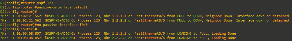
Repeat the process on D2.


Step 2: Adjust OSPF link costs.
The OSPF path metric is based on the cumulative interface cost to the network. OSPF assigns the OSPF link cost using the formula Cost = Reference Bandwidth / Interface Bandwidth. The default reference bandwidth is 100 Mbps, therefore, the default formula is Cost = 100,000,000/Interface Bandwidth. For example, a FastEthernet interface would be assigned a cost of 1 (i.e., 100,000,000 / 100,000,000).
However, the default reference bandwidth does not differentiate interfaces faster than FastEthernet. Therefore, OSPF assigns the identical cost of “1”to FastEthernet, Gigabit Ethernet, and 10 GE interfaces. OSPF makes no distinction that the Gig and 10GE interfaces are faster.
Use the auto-cost reference-bandwidth bandwidth-mbps router configuration command to change the reference bandwidth as follows:
auto-cost reference-bandwidth 100– Assigns the default reference bandwidth to 100 Mbps which is the default setting. With this setting, FastEthernet = 1, GigabitEthernet = 1, and 10GE = 1.auto-cost reference-bandwidth 1000– Assigns the default reference bandwidth to 1 Gbps. With this setting, FastEthernet = 10, GigabitEthernet = 1, and 10GE = 1.auto-cost reference-bandwidth 10000– Assigns the default reference bandwidth to 10 Gbps. With this setting, FastEthernet = 100, GigabitEthernet = 10, and 10GE = 1.
Note: The auto-cost reference-bandwidth must be the same on all routers in the area. Otherwise suboptimal routing may occur.
-
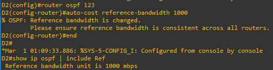
On R1, change the reference bandwidth to account for the Gigabit interfaces as shown. Verify that the reference bandwidth has changed to account for the Gigabit interfaces using the
show ip ospfcommand.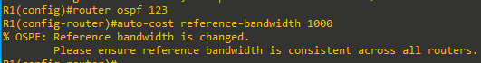
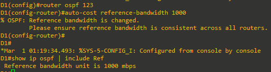
Not able to verify on the 2621 (the line is not there). -
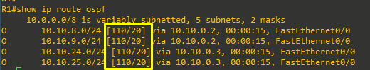
Repeat the steps on D1 and D2 to change the reference bandwidth to account for the Gigabit interfaces.
- Verify the routing tables to see if the route metrics have increased.


Step 3. Alter Hello and Dead interval timers
OSPF Hello messages are exchanged to establish a neighbor relationship and to ensure that adjacent OSPF neighbors are still available. OSPF uses a hello timer and a dead interval timer which is four times the hello timer.
When a router receives a Hello packet, the dead interval resets and starts to decrement again. If subsequent hello packets are not received before the OSPF dead interval timer reaches 0, the neighbor state is changed to down. The router then sends out the appropriate topology change LSA to all other peers and the SPF algorithm must be recalculated on all routers in the area.
The default OSPF hello timer interval varies based on the OSPF network type. On broadcast and point-to-point links, the default hello timer interval is 10 seconds and dead timer interval is 40 seconds. On non-broadcast multiaccess (NBMA) and point-to-multipoint networks, the default hello interval is 30 seconds with a dead timer interval of 120 seconds.
You can alter the hello timer interval with values between 1 and 65,535 seconds using the ip ospf hello-interval seconds interface configuration command.
The dead interval can be modified using the ip ospf dead-interval seconds interface configuration command. However, the command is really not required because changing the hello timer interval automatically modifies the default dead interval.
-
On R1, change the hello interval on the F0/0 interface to 5 seconds and a dead interval time to 20 seconds.
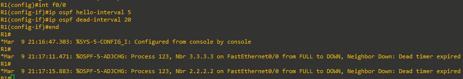
Notice how R1 has received OSPF adjacency change messages for D1 and D2. The reason is because OSPF timers must match between interconnecting peers. Therefore, the D1 and D2 F0/5 interface must also be configured with the identical timers.
-
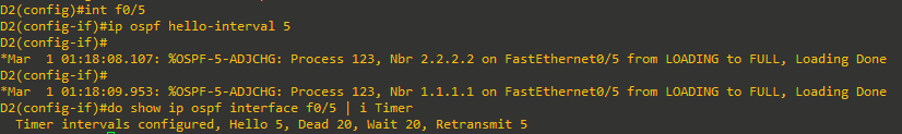
Verify that the timers have changed on F0/0 using the
show ip ospf interfacecommand.
-
Configure D1 with the identical hello and dead interval timers on F0/5 and verify.


Notice the first OSPF adjacency change message indicating that D1 had lost adjacency with R1. After the commands are entered, the next OSPF adjacency change message indicates that the adjacency with R1 has been re-established. However, the second adjacency change message indicates that the adjacency with D2 has been lost because its timers are not matching.
-
Configure D2 with the identical hello and dead interval timers on F0/5 and verify.

Again, notice the existing OSPF adjacency change messages indicating that D2 had lost adjacency with R1 and D1.
After the commands are entered, the next OSPF adjacency change messages indicate adjacencies with R1 and D1 have been re-established. And again, the dead interval was automatically adjusted without having to configure the ip ospf dead-interval 20 command on the interface.


Part 5: DR and BDR Placement
In this part, you will configure OSPF DR and BDR placement on the multiaccess network.
By default, an OSPF router tries to establish neighbor adjacencies with all other OSPF routers. This is a concern with large multiaccess (i.e. Ethernet) networks. For instance, 10 routers interconnected to the same Layer 2 switch would require a total of 45 adjacencies to be established. This can cause excessive OSPF traffic and waste router resources.
For this reason, OSPF routers interconnected to the same multiaccess network elect a designated router (DR) and a backup designated router (BDR). All non-DR and BDR routers are referred to as DROTHERS and only form adjacencies with DR and BDR routers. This reduces the total number of adjacencies and improves network operations.
DR and BDR are automatically elected during the last phase of the 2-Way OSPF neighbor state, before the ExStart state.
DR and BDR elections are conducted as follows:
- An OSPF router interface with a priority greater than 0 attempts to become BDR on the link.
- If no BDR exists, then it elects itself the BDR. If there is a tie with another router, the highest router ID is used.
- If there is no DR, the BDR promotes itself as DR.
- The neighbor with the next highest priority is elected BDR.
The DR and BDR are the central focal points on a multiaccess network. In a large network, it is advantageous to choose which router should be DR and BDR.
When all OSPF routers have the same OSPF priority, the election is based on the higher router ID. Altering router ID to choose DR/BDR routers may not be convenient. A better alternative is to alter the interface priority.
By default, all OSPF routers on a multiaccess network have a priority of 1 assigned. An interface priority can be changed using the ip ospf priority value interface configuration command. The value can be between 0 and 255. Setting the value to 0 ensures the router will never become a DR or BDR. Setting the value greater than the default value of 1, makes the router a candidate to become the DR or BDR.
Note: It may be necessary to use the clear ip ospf process to ensure the proper devices are elected.
Step 1: Verify current DR and BDR selection
In the topology, R1, D1, and D2 are interconnected on the same Ethernet network. Therefore, a DR/BDR election has already transpired. The easiest way to determine the interface role is by viewing the OSPF interface with the show ip ospf neighbor command.
-
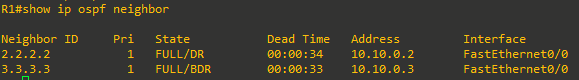
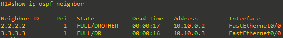
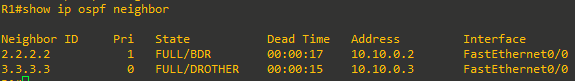
On R1, verify the current DR/BDR status using the
show ip ospf neighborcommand.
From the perspective of R1, D1 (i.e., 2.2.2.2) is a DROTHER and D2 (i.e., router ID 3.3.3.3) is the DR. We must then assume that R1 is the BDR. -
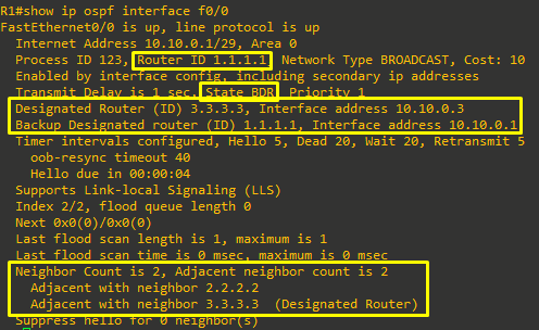
Verify the current status of R1 using the
show ip ospf interface G0/0/1command.
The output confirms that R1 is the BDR and that D2 (i.e., 3.3.3.3) is the DR.
-
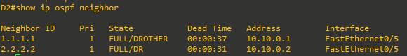
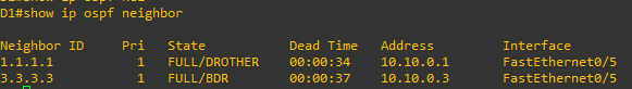
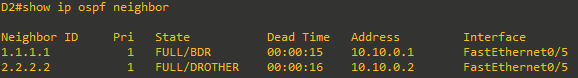
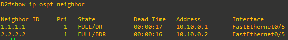
Verify the current DR/BDR status on D1 and D2 using the
show ip ospf neighborcommand.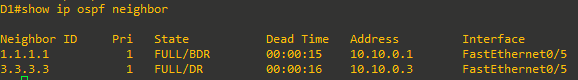


Step 2: Change DR and BDR selection
It is sometimes advantageous to choose which router is selected as DR and BDR. For example, we will change the DR and BDR assignment as follows:
- R1 is currently the BDR but should be the DR using a priority of 255.
- D1 is currently a DROTHER but should be the BDR using the default priority.
- D2 is currently DR but should never become DR or BDR using a priority of 0.
- Starting on D2, enter interface F0/5 and set the priority to 0 as shown.

Notice the OSPF message. The reason is because D1 (i.e., 2.2.2.2) just assumed either the DR or BDR role and has established an adjacency with D2.
- Verify the current DR / BDR placement.
The output confirms that R1 (i.e., 1.1.1.1) is now the DR and D1 (i.e., 2.2.2.2) is the BDR.
The reason R1 became the DR is because it had already been elected as BDR. When a DR fails, the elected BDR is automatically elected as DR to avoid network instability.
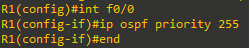
-
Although R1 is already the DR, change the interface priority to ensure it is always a candidate to be DR.


-
Verify the roles of D1 and D2.


Device Configs - Final
Router R1
R1#sh run
Building configuration...

Current configuration : 1347 bytes
!
version 12.4
service timestamps debug datetime msec
service timestamps log datetime msec
no service password-encryption
!
hostname R1
!
boot-start-marker
boot-end-marker
!
!
no aaa new-model
no network-clock-participate slot 1
no network-clock-participate wic 0
ip cef
!
!
!
!
no ip domain lookup
ip auth-proxy max-nodata-conns 3
ip admission max-nodata-conns 3
!
!
!
!
!
!
!
!
!
!
!
!
!
!
!
!
!
!
!
!
!
!
!
!
interface Loopback0
 ip address 209.165.200.225 255.255.255.224
!
interface Loopback1
 ip address 192.168.1.1 255.255.255.192
 ip ospf network point-to-point
 ip ospf 123 area 0
!
interface FastEthernet0/0
 ip address 10.10.0.1 255.255.255.248
 ip ospf hello-interval 5
 ip ospf priority 255
 ip ospf 123 area 0
 duplex auto
 speed auto
!
interface Serial1/0
 no ip address
 shutdown
 no fair-queue
!
interface Serial1/1
 no ip address
 shutdown
!
interface Serial1/2
 no ip address
 shutdown
!
interface Serial1/3
 no ip address
 shutdown
!
router ospf 123
 router-id 1.1.1.1
 log-adjacency-changes
 auto-cost reference-bandwidth 1000
 passive-interface Loopback1
 default-information originate
!
ip forward-protocol nd
ip route 0.0.0.0 0.0.0.0 Loopback0
!
!
ip http server
no ip http secure-server
!
!
!
!
control-plane
!
!
!
!
!
!
!
!
!
!
line con 0
 exec-timeout 0 0
 logging synchronous
line aux 0
line vty 0 4
 login
!
!
end
Switch D1
D1#sh run
Building configuration...

Current configuration : 1341 bytes
!
! Last configuration change at 01:27:08 UTC Mon Mar 1 1993
!
version 15.0
no service pad
service timestamps debug datetime msec
service timestamps log datetime msec
no service password-encryption
!
hostname D1
!
boot-start-marker
boot-end-marker
!
!
!
no aaa new-model
system mtu routing 1500
ip routing
no ip domain-lookup
!
!
!
!
!
!
!
!
!
!
!
spanning-tree mode pvst
spanning-tree extend system-id
!
vlan internal allocation policy ascending
!
!
!
!
!
!
!
!
!
!
!
!
!
!
!
interface FastEthernet0/1
 no switchport
 ip address 10.10.8.1 255.255.255.0
!
interface FastEthernet0/2
 no switchport
 ip address 10.10.9.1 255.255.255.0
!
interface FastEthernet0/3
!
interface FastEthernet0/4
!
interface FastEthernet0/5
 no switchport
 ip address 10.10.0.2 255.255.255.248
 ip ospf hello-interval 5
!
interface FastEthernet0/6
!
interface FastEthernet0/7
!
interface FastEthernet0/8
!
interface GigabitEthernet0/1
!
interface Vlan1
 no ip address
!
router ospf 123
 router-id 2.2.2.2
 auto-cost reference-bandwidth 1000
 passive-interface default
 no passive-interface FastEthernet0/5
 network 10.10.0.2 0.0.0.0 area 0
 network 10.10.8.1 0.0.0.0 area 0
 network 10.10.9.1 0.0.0.0 area 0
!
ip http server
ip http secure-server
!
!
!
!
!
vstack
!
line con 0
 exec-timeout 0 0
 logging synchronous
line vty 0 4
 login
line vty 5 15
 login
!
end
Switch D2
D2#show run
Building configuration...

Current configuration : 1369 bytes
!
! Last configuration change at 01:25:46 UTC Mon Mar 1 1993
!
version 15.0
no service pad
service timestamps debug datetime msec
service timestamps log datetime msec
no service password-encryption
!
hostname D2
!
boot-start-marker
boot-end-marker
!
!
!
no aaa new-model
system mtu routing 1500
ip routing
no ip domain-lookup
!
!
!
!
!
!
!
!
!
!
!
spanning-tree mode pvst
spanning-tree extend system-id
!
vlan internal allocation policy ascending
!
!
!
!
!
!
!
!
!
!
!
!
!
!
!
interface FastEthernet0/1
 no switchport
 ip address 10.10.24.1 255.255.255.0
!
interface FastEthernet0/2
 no switchport
 ip address 10.10.25.1 255.255.255.0
!
interface FastEthernet0/3
!
interface FastEthernet0/4
!
interface FastEthernet0/5
 no switchport
 ip address 10.10.0.3 255.255.255.248
 ip ospf hello-interval 5
 ip ospf priority 0
!
interface FastEthernet0/6
!
interface FastEthernet0/7
!
interface FastEthernet0/8
!
interface GigabitEthernet0/1
!
interface Vlan1
 no ip address
!
router ospf 123
 router-id 3.3.3.3
 auto-cost reference-bandwidth 1000
 passive-interface default
 no passive-interface FastEthernet0/5
 network 10.10.0.0 0.0.0.7 area 0
 network 10.10.24.0 0.0.0.255 area 0
 network 10.10.25.0 0.0.0.255 area 0
!
ip http server
ip http secure-server
!
!
!
!
!
vstack
!
line con 0
 exec-timeout 0 0
 logging synchronous
line vty 0 4
 login
line vty 5 15
 login
!
end

D2#