Lab - Implement RSTP and Advanced STP Modifications
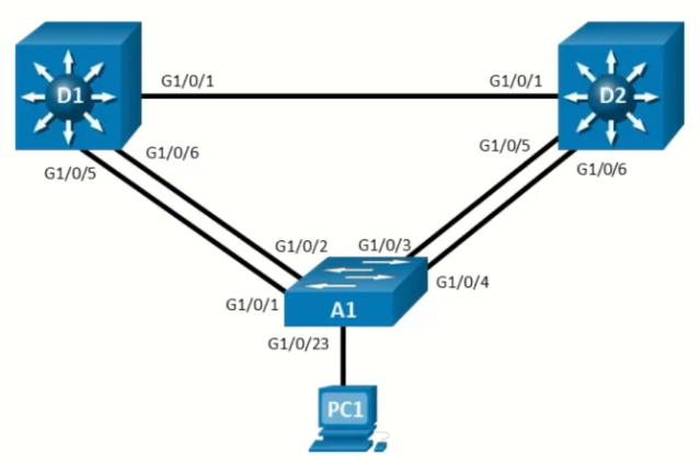
Topology
Objectives
- Part 1: Build the Network and Configure Basic Device Settings
- Part 2: Observe STP Convergence and Topology Change
- Part 3: Configure and Verify Rapid Spanning Tree
- Part 4: Implement and Observe Various Topology Tuning Methods
- Part 5: Implement and Observe Various Topology Protection Mechanisms
Background / Scenario
The potential effect of a loop in the Layer 2 network is significant, as it can disrupt both connected hosts an network equipment. Spanning Tree Protocol (STP) was developed to prevent these loops, and while it works “out of the box,” its default decisions do not always align with the optimal logical topology for your network. In this lab, you will first observe the operation of spanning tree protocols, including Rapid Spanning Tree Protocol (RSTP), to see how they protect the Layer 2 network from loops and topology disruptions. You will also work with Multiple Spanning Tree (MST), which allows you to group VLANs into separate spanning-tree instances for greater efficiency and control. You will then configure and test advanced STP features to adjust the logical topology to your requirements and explore protection mechanisms that strengthen stability and resilience. The terms “switch” and “bridge” will be used interchangeably throughout the lab.
Note: This lab is an exercise in deploying and verifying various STP mechanisms. It does not reflect networking best practices.
Note: The switches used with CCNP hands-on labs are Cisco 9300L with Cisco IOS XE release 17.12.05 (universalk9 image) and Cisco 9200L with IOS-XE release 17.12.05 (universalk9 image). Other routers and Cisco IOS versions can be used. Depending on the model and Cisco IOS version, the commands available and the output produced might vary from what is shown in the labs.
Note: Ensure that the switches have been erased and have no startup configurations.
Required Resources - Sergio Jiménez's Version
- 2 Switches (Cisco 3560)
- 1 Switch (Cisco 2960CX)
- 1 PC
- Console cables to configure the Cisco IOS devices via the console ports
- Ethernet cables as shown in the topology
Instructions
Part 1: Build the Network and Configure Basic Device Settings and Interface Addressing
In Part 1, you will set up the network topology and configure basic settings and interface addressing on routers.
Step 1: Cable the network as shown in the topology
Attach the devices as shown in the topology diagram, and cable as necessary.
Step 2: Configure basic settings for each switch.
- Console into each switch, enter global configuration mode, and apply the basic settings. The startup configurations for each device are provided below.
Switch D1
Switch D2hostname D1 spanning-tree mode pvst spanning-tree pathcost method long banner motd # D1, Implement RSTP and Advanced STP Modifications Lab # line con 0 exec-timeout 0 0 logging synchronous exit interface range f0/1, f0/5-6 switchport trunk encapsulation dot1q switchport mode trunk no shutdown exit vlan 2 name SecondVLAN exit interface vlan 1 ip address 10.0.0.1 255.0.0.0 no shut exit
Switch A1hostname D2 banner motd # D2, Implement RSTP and Advanced STP Modifications Lab # spanning-tree mode pvst spanning-tree pathcost method long line con 0 exec-timeout 0 0 logging synchronous exit interface range f0/1, f0/5-6 switchport trunk encapsulation dot1q switchport mode trunk no shutdown exit vlan 2 name SecondVLAN exit interface vlan 1 ip address 10.0.0.2 255.0.0.0 no shut exit
Note: Outputs and Spanning Tree topologies highlighted in this lab may be different than what you observe using your own equipment. It is critically important for you to understand how Spanning Tree makes its decisions, and how those decisions impact the operational topology of the network.hostname A1 banner motd # A1, Implement RSTP and Advanced STP Modifications Lab # spanning-tree mode pvst spanning-tree pathcost method long spanning-tree vlan 1 priority 61440 spanning-tree vlan 2 priority 61440 line con 0 exec-timeout 0 0 logging synchronous exit interface range g0/1-4 switchport mode trunk no shutdown exit vlan 2 name SecondVLAN interface vlan 1 ip address 10.0.0.3 255.0.0.0 no shut exit
Part 2: Discover the Default Spanning Tree
Our switches are running the Cisco default PVST+, and we have two VLANs in the network, so we should see two root bridges.
Step 1: Find the root bridge and root ports.
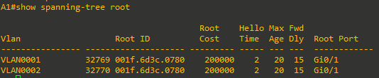
- On A1, issue the command show spanning-tree root and observe what the output tells you about the root bridge. Amongst the lab devices being used to document this lab, A1 shows the root id with a cost of 20000 and the root port as interface GigabitEthernet 1/0/1 for both VLAN1 and VLAN2.
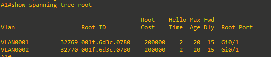
Because we know from the physical topology diagram that A1 is connected to D1 using G0/1, and that interface is a GigabitEthernet interface, therefore having a cost of 20000, D1 is the root bridge for both VLAN 1 and VLAN 2. The question at this point is – why?
-
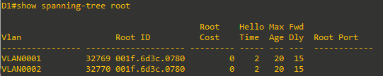
The root bridge is elected based upon which switch has the highest Bridge ID (BID). The BID is made up of a configurable priority value (which defaults to 32768) and the base MAC address for the switch. Use the command show spanning-tree root to gather that information from your switches to support the root bridge decision.


- What are the base MAC addresses for the devices we are using? Issue the command show version | include MAC (capitalized exactly like that) on each switch.


Amongst the three switches being used to document this lab, D1 has the lowest base MAC address.
Each switch that is not the root will have one single root port for each VLAN. In this case, the root port is F0/1 - G0/1 for both VLANs and both A1 and D2. This port represents the lowest Path Cost to the root bridge. Path Cost is the total of the Port Costs in the path to the root bridge. Because A1 and D2 have direct connections to the root, Port cost and Path cost are the same. The Port Cost is based upon the bandwidth value of the port, and it can either be dynamically assigned or statically configured.


Step 2: Identify Designated Ports
The Spanning Tree Designated Port can be traced back to the early versions of the protocol, which were developed when LAN segments were shared, multiaccess networks. In these networks, there was a very real possibility that there could be users attached to a segment between two switches.
The job of the Designated Port back then was to ensure that users had a way to access the network from a given segment, and there was always one Designated Port on each segment. In the switched networks of today, there are very few shared segments, so the job of the Designated Port is more to help maintain the network topology.
A Designated Port stays active in the topology, both sending BPDUs and learning MAC addresses. Every port on the Root Bridge is a Designated Port. Further, there is one Designated Port on every segment that is not attached directly to the root.
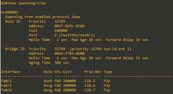
- On D2, issue the show spanning-tree command, and you will see that there are two ports now identified as being in the Designated Port role.
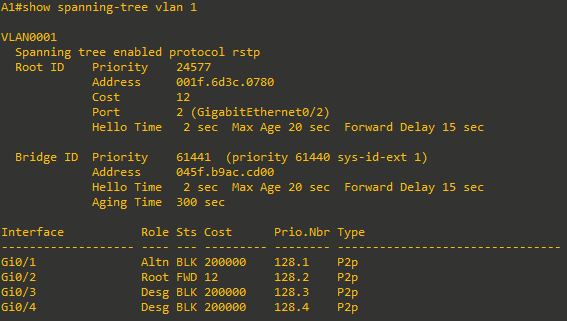
- And now look at the segments from the A1 side. Issue the show spanning-tree command on A1.
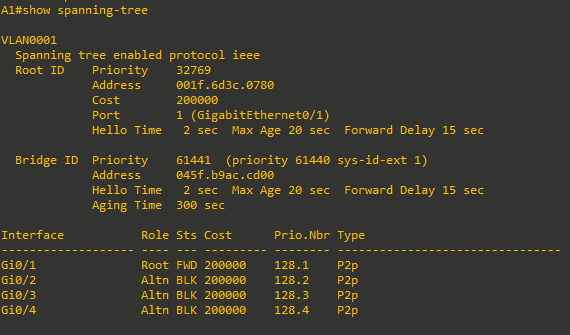
Interfaces G0/3 and G0/4 on A1 are in the Alternate Role, which is the Cisco PVST+ version of the IEEE 802.1D Discarding role. These interfaces are up and receiving BPDUs from the Designated Ports on each segment, but they will not learn MAC addresses or forward traffic until they stop receiving those BDPUs and move to the Designated state. - You may have noticed in the previous output that one of the two links from A1 to D1 was not being used.

Each switch can only have a single root port. In this example, G0/2, which is in the Alternate Role, would only take over if G0/1 were to fail. The decision about which interface to use in this scenario is based on the lowest port priority, which defaults to 128.interface_id.


Part 3: Implement and Observe Rapid Spanning Tree Protocol
In Part 3, you will implement Rapid Spanning Tree Protocol (RSTP) on all the switches. Using the same basic rules, RSTP speeds up convergence significantly.
- On D2, issue the debug spanning-tree events command, and then issue the shutdown command for interface F0/1 and observe the output.
From the above output, you can see that it took a total of about 17 seconds for spanning tree to adjust to the topology change. Rapid Spanning Tree can adjust much faster. On D2, turn off debugging and reactivate the F0/1 interface.D2#debug spanning-tree events Spanning Tree event debugging is on D2#conf t Enter configuration commands, one per line. End with CNTL/Z. D2(config)#int f0/1 D2(config-if)#sh D2(config-if)# *Mar 1 06:22:25.425: %LINK-5-CHANGED: Interface FastEthernet0/1, changed state to administratively down *Mar 1 06:22:26.432: %LINEPROTO-5-UPDOWN: Line protocol on Interface FastEthernet0/1, changed state to down D2(config-if)# *Mar 1 06:22:41.481: STP: VLAN0001 heard root 32769-001f.6d3c.0780 on Fa0/5 *Mar 1 06:22:41.481: supersedes 32769-0024.f785.0b00 *Mar 1 06:22:41.481: STP: VLAN0001 new root is 32769, 001f.6d3c.0780 on port Fa0/5, cost 400000 *Mar 1 06:22:41.481: STP: VLAN0001 sent Topology Change Notice on Fa0/5 *Mar 1 06:22:41.481: STP: VLAN0002 heard root 32770-001f.6d3c.0780 on Fa0/5 *Mar 1 06:22:41.481: supersedes 32770-0024.f785.0b00 *Mar 1 06:22:41.481: STP: VLAN0002 new root is 32770, 001f.6d3 D2(config-if)#c.0780 on port Fa0/5, cost 400000 *Mar 1 06:22:41.481: STP: VLAN0002 sent Topology Change Notice on Fa0/5 *Mar 1 06:22:41.481: STP[1]: Generating TC trap for port FastEthernet0/6 *Mar 1 06:22:41.481: STP: VLAN0001 Fa0/6 -> blocking *Mar 1 06:22:41.481: STP[2]: Generating TC trap for port FastEthernet0/6 *Mar 1 06:22:41.481: STP: VLAN0002 Fa0/6 -> blocking -
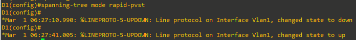
On D1, change the spanning tree mode to rapid-pvst:

From the above output, you can see that it took more than 30 seconds for interface VLAN1 to come back up. For an SVI (Switched Virtual Interface) to be operational, two conditions must be met:
1) The VLAN associated with the SVI must exist on the switch.
2) The VLAN must be in spanning tree forwarding mode on at least one interface.
Both conditions must be true for the SVI to function properly. It took 30 seconds to adjust. What happened to “rapid”? -
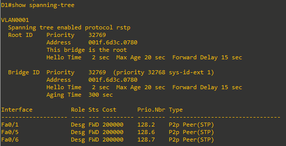
On D1, issue the command show spanning-tree.
- On D2 and A1, change the spanning tree mode to rapid spanning tree. On A1, first issue the debug spanning-tree events command, and then change the mode.
A1 was the last switch that was configured for RSTP. As you can see from the debug output it took approximately .600 milliseconds for RSTP to calculate STP instances for VLAN 1 and VLAN 2. This is the “rapid” in rapid spanning tree.A1(config)#spanning-tree mode rapid-pvst A1(config)# Jan 1 06:36:56.596: setting bridge id (which=3) prio 61441 prio cfg 61440 sysid 1 (on) id F001.045f.b9ac.cd00 Jan 1 06:36:56.596: RSTP(1): initializing port Gi0/1 Jan 1 06:36:56.596: RSTP(1): Gi0/1 is now designated Jan 1 06:36:56.596: RSTP(1): initializing port Gi0/2 Jan 1 06:36:56.596: RSTP(1): Gi0/2 is now designated Jan 1 06:36:56.596: RSTP(1): initializing port Gi0/3 Jan 1 06:36:56.596: RSTP(1): Gi0/3 is now designated Jan 1 06:36:56.596: RSTP(1): initializing port Gi0/4 Jan 1 06:36:56.596: RSTP(1): Gi0/4 is now designated Jan 1 06:36:56.596: setting bridge id (which=3) prio 61442 prio cfg 61440 sysid 2 (on) id F002.045f.b9ac.cd00 Jan 1 06:36:56.596: RSTP(2): initializing port Gi0/1 Jan 1 06:36:56.596: RSTP(2): Gi0/1 is now designated Jan 1 06:36:56.596: RSTP(2): initializing port Gi0/2 Jan 1 06:36:56.596: RSTP(2): Gi0/2 is now designated Jan 1 06:36:56.600: RSTP(2): initializing port Gi0/3 Jan 1 06:36:56.600: RSTP(2): Gi0/3 is now designated Jan 1 06:36:56.600: RSTP(2): initializing port Gi0/4 Jan 1 06:36:56.600: RSTP(2): Gi0/4 is now designated Jan 1 06:36:56.600: RSTP(1): transmitting a proposal on Gi0/1 Jan 1 06:36:56.600: RSTP(1): transmitting a proposal on Gi0/2 Jan 1 06:36:56.603: RSTP(1): transmitting a proposal on Gi0/3 Jan 1 06:36:56.603: RSTP(1): transmitting a proposal on Gi0/4 Jan 1 06:36:56.603: RSTP(2): transmitting a proposal on Gi0/1 Jan 1 06:36:56.603: RSTP(2): transmitting a proposal on Gi0/2 Jan 1 06:36:56.603: RSTP(2): transmitting a proposal on Gi0/3 Jan 1 06:36:56.603: RSTP(2): transmitting a proposal on Gi0/4 Jan 1 06:36:56.603: %LINEPROTO-5-UPDOWN: Line protocol on Interface Vlan1, changed state to down Jan 1 06:36:56.614: RSTP(1): updt roles, received superior bpdu on Gi0/1 Jan 1 06:36:56.614: RSTP(1): Gi0/1 is now root port Jan 1 06:36:56.614: RSTP(1): syncing port Gi0/2 Jan 1 06:36:56.614: RSTP(1): syncing port Gi0/3 Jan 1 06:36:56.614: RSTP(1): syncing port Gi0/4 Jan 1 06:36:56.614: RSTP(1): updt roles, received superior bpdu on Gi0/2 Jan 1 06:36:56.614: RSTP(1): Gi0/2 is now alternate Jan 1 06:36:56.617: RSTP(2): updt roles, received superior bpdu on Gi0/1 Jan 1 06:36:56.617: RSTP(2): Gi0/1 is now root port Jan 1 06:36:56.617: RSTP(2): syncing port Gi0/2 Jan 1 06:36:56.617: RSTP(2): syncing port Gi0/3 Jan 1 06:36:56.617: RSTP(2): syncing port Gi0/4 Jan 1 06:36:56.617: RSTP(2): updt roles, received superior bpdu on Gi0/2 Jan 1 06:36:56.617: RSTP(2): Gi0/2 is now alternate Jan 1 06:36:56.621: STP[1]: Generating TC trap for port GigabitEthernet0/1 Jan 1 06:36:56.624: STP[2]: Generating TC trap for port GigabitEthernet0/1 Jan 1 06:36:56.624: %LINEPROTO-5-UPDOWN: Line protocol on Interface Vlan1, changed state to up Jan 1 06:36:56.628: RSTP(1): transmitting a proposal on Gi0/3 Jan 1 06:36:56.631: RSTP(1): transmitting a proposal on Gi0/4 Jan 1 06:36:56.631: RSTP(2): transmitting a proposal on Gi0/3 Jan 1 06:36:56.631: RSTP(2): transmitting a proposal on Gi0/4 Jan 1 06:36:56.642: RSTP(1): updt roles, received superior bpdu on Gi0/4 Jan 1 06:36:56.642: RSTP(1): Gi0/4 is now alternate Jan 1 06:36:56.642: RSTP(1): synced Gi0/1 Jan 1 06:36:56.642: RSTP(2): updt roles, received superior bpdu on Gi0/4 Jan 1 06:36:56.642: RSTP(2): Gi0/4 is now alternate Jan 1 06:36:56.642: RSTP(2): synced Gi0/1 Jan 1 06:36:56.659: RSTP(1): updt roles, received superior bpdu on Gi0/3 Jan 1 06:36:56.659: RSTP(1): Gi0/3 is now alternate Jan 1 06:36:56.659: RSTP(2): updt roles, received superior bpdu on Gi0/3 Jan 1 06:36:56.659: RSTP(2): Gi0/3 is now alternate - Turn off debugging on A1.

Part 4: Implement and Observe Various Topology Tuning Methods
In Part 4, you will implement various topology tuning methods.
Step 1: Controlling the Root Bridge
The current root bridge was elected based on the lowest Bridge ID (consisting of the Priority, extended system ID equal to the VLAN ID, and base MAC address values).
With the priority and extended system IDs being identical, the root bridge’s MAC is numerically smaller than the local bridge’s MAC. The result is that in a completely un-configured network, one single switch will be elected as the root bridge. The resulting choice of switch may or may not be desirable.
There are two basic ways to manipulate the configuration to control the location of the root bridge:
- The spanning-tree vlan vlan-id priority value command can be used to manually set a priority value
- The spanning-tree vlan vlan-id root { primary | secondary } command can be used to automatically set a priority value.
The difference between the two is that the priority command will set a specific number (multiple of 4096) as the priority. This number must be an increment of 4096. The root primary command will set the local bridge’s priority to 24,576 (if the local bridge MAC is lower than the current root bridge’s MAC) or 4096 lower than the current root’s priority (if the local bridge MAC is higher than the current root bridge’s MAC). Notice that 24,576 is the sixth increment of 4096.
The logic behind this operation is straight-forward. The root primary command tries to lower the priority only as much as is needed to win the root election, while leaving priorities between 24576 and the default 32768 for use by secondary bridges. The command always takes the entire Bridge ID into account when computing the resulting priority value.
The spanning-tree vlan vlan-id root secondary command will statically set the local bridge’s priority to 28,672. In an otherwise unconfigured network where all switch priorities default to 32,768, the root primary command will set the priority on the switch to 24,576 (two 4096 increments lower than the default priority) while the root secondary command will set the priority on the secondary root to the 28,672 (one 4096 increment lower than the default priority).
- Modify D1 and D2 so that D1 is elected the primary root bridge for VLAN 1 and D2 is elected the primary root bridge for VLAN 2. D1 should be elected as the secondary root bridge for VLAN 2, and D2 should be elected as the secondary root bridge for VLAN 1. You will need to make configuration changes on both D1 and D2.
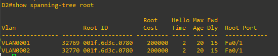
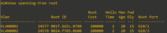
D1(config)# spanning-tree vlan 1 root primary D1(config)# spanning-tree vlan 2 root secondary D2(config)# spanning-tree vlan 2 root primary D2(config)# spanning-tree vlan 1 root secondary - After you have configured both D1 and D2, go to A1 and issue the command show spanning-tree root. In this output you will see the root bridges differentiated.

From the above output, you can see that the root port for VLAN 1 is G0/1 and the root port for VLAN 2 is G0/3.
Step 2: Adjust port cost values to impact root and designated port selection.
As the network is implemented right now, there are two direct paths between switch A1 and the root bridge for each VLAN. Path and port costs are evaluated to determine the shortest path to the root bridge. In the case where there are multiple equal cost paths to the root bridge, additional attributes must be evaluated. In our case, the lower interface number (for example, G0/1) is chosen as the Root Port, and the higher interface numbers (for example, G0/2) are put into a spanning tree Discarding state.
You can see which ports are blocked with the show spanning-tree vlan-id command or the show spanning-tree blockedports command. For now, examine VLAN 1 on D1.
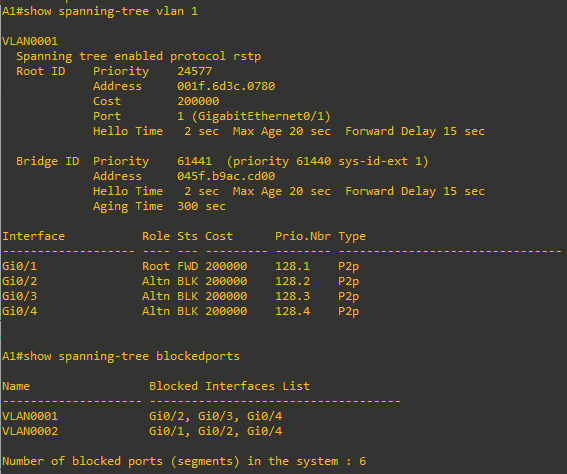
- On A1, issue the commands show spanning-tree vlan 1 and show spanning-tree blockedports.

As you can see, because VLAN 1 has its Root Port on G0/1, the Alternate Blocking Ports are G0/2, G0/3, and G0/4.
To manipulate which port becomes the Root Port on non-root bridges, change the port cost or port priority value. Remember that this change could have an impact on downstream switches as well.
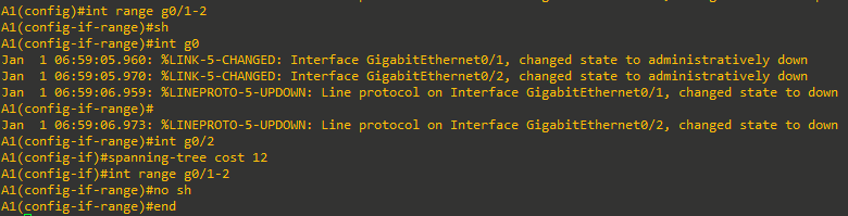
Note: The changes you are about to implement are considered topology changes and could have a significant impact on the overall structure of the spanning tree in your switch network. Do not make these changes in a production network without careful planning and prior coordination. - On A1, shut down interfaces G0/1 and G0/2, assign a new port cost to G0/2, and then issue no shutdown to the ports.
- Now verify that this impacts root port selection on A1 using the show spanning-tree vlan 1 command.

From the output you can see that the root port selected by A1 for VLAN 1 is now interface G0/2, and the port (and root) cost is now 12.

Step 3: Adjust port priority values to impact root port selection
The next method to impact root port selection is configured on the root bridge itself. In our current network topology, A1 has two connections to the root bridge for VLAN 2, switch D2. The root port has been selected, in this case based on the lowest port ID. Port ID is made up of two values, labeled as Prio (Priority) and Nbr (Number).
Note: The port number is not necessarily equal to the interface ID. A switch may use any port number for STP purposes if they are unique for each port on the switch.
The port priority can be any value between 0 and 240, in increments of 16 (older switches may allow setting the priority in different increments).
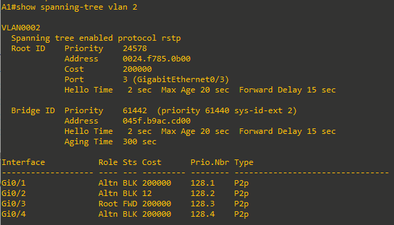
- On A1, issue the command show spanning-tree vlan 2 and take note of the port ID values listed.

As expected with two equal-cost paths to the root bridge, the lower port ID was selected as the root port. -
Modify the port priority of D2 interface F0/6 so that it becomes the preferred port.
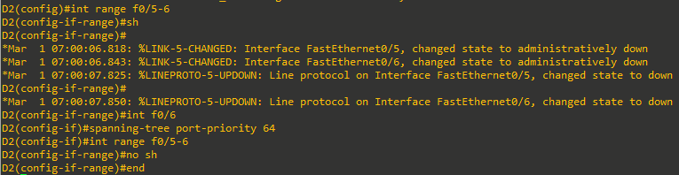
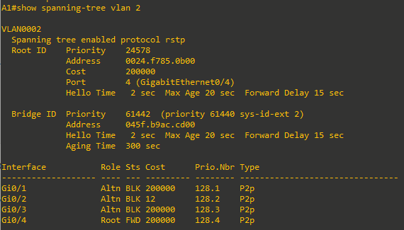
- On A1, issue the show spanning-tree vlan 2 command and you will see that G0/4 is now the selected root port. This selection is based on the lower priority value of D2 interface F0/6. Notice that the lower priority value does not appear in any A1 output.


Step 4: Implement Spanning Tree PortFast
In STP and RSTP, new ports must be checked for switching loops before entering the Forwarding state, which can take up to 30 seconds. This check is unnecessary for ports connected to end devices (like workstations, printers, or servers), because they do not create loops. In RSTP, these are called edge ports; others are non-edge ports.
Edge ports can transition to the Forwarding state immediately upon connection. Cisco’s PortFast feature lets you manually designate a port as an edge port, bypassing the normal waiting period for all STP versions.
Edge ports are especially important in RSTP and MSTP. When a switch receives a Proposal on its Root port, it temporarily blocks (Discards) all non-edge Designated ports to prevent loops (the “Sync” process). Only after receiving Agreements from downstream switches do these ports return to Forwarding. If an end device is connected to a port not configured as edge (PortFast), it will be blocked for up to 30 seconds during this Sync process, causing connectivity delays.
Properly configuring ports connected to end devices as edge ports is critical for fast, reliable network convergence with RSTP. By default, Cisco switches treat all ports as non-edge ports, so manual configuration is necessary.
Let’s see this in action for PC1 that is connected to A1.
-
Ensure that PC1 is turned on. You can configure it according to the Addressing Table, but it is not necessary for testing PortFast.
- On A1, issue the command debug spanning-tree events, then issue the no shutdown command for interface G1/0/23, wait a few seconds, and issue the shutdown command. The log output will appear something like the output below.
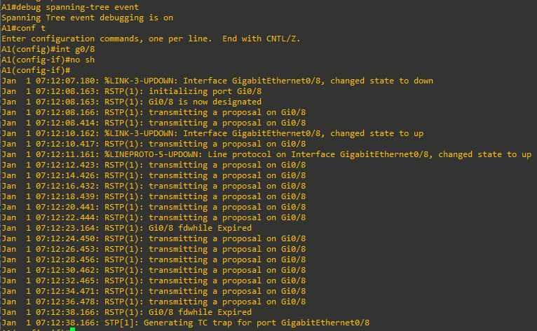
What you see here is the switch trying to go through the Proposal/Agreement process on G0/8. But there is no point in this because the device connected to G0/8 is an endpoint and does not understand Spanning Tree. As noted by the highlighted timestamps, this adds the potential of a 30-second delay before the host can send data, such as a DHCP request to the network. - On A1, configure interface G0/8 with the spanning-tree portfast command followed by the no shutdown command. This designates G0/8 as an interface that will never be connected to another switch, and therefore; it will never cause a loop in the topology, and subsequently allow that interface to go into forwarding mode immediately. Observe the output.
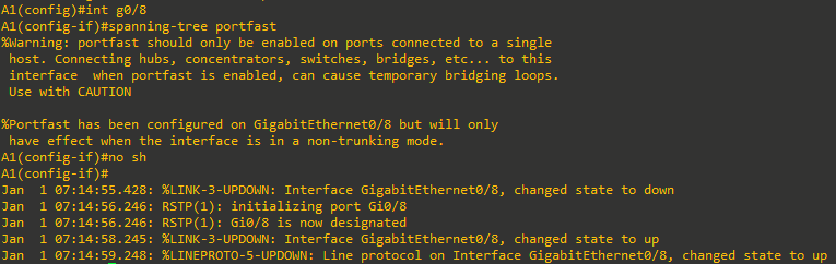
From the output you can see that RSTP sees G0/8 as designated, and never sends a proposal on the interface, because of the portfast setting. The port comes up in less than 2 seconds.
There are two other ways to configure an interface as a portfast port; using the switchport host interface configuration command and using the spanning-tree portfast default global configuration command.
- switchport host not only enables portfast, but also statically sets the interface mode to access and disables aggregation protocols.
- The spanning-tree portfast default command sets the default state of interfaces that are configured as access ports with portfast enabled. All you must do is configure the interface with switchport mode access and portfast is engaged on that interface.
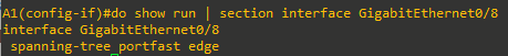
Verifying that a port is in portfast mode can be done by looking at the running-configuration, as shown below:

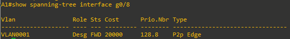
You can also verify portfast mode by examining spanning-tree details for the port. For example, use the show spanning-tree interface interface-id command to verify that the interface is in Edge mode, as shown below:
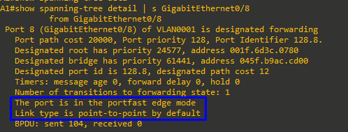
Or, issue the command show spanning-tree detail | section FastEthernet0/23, as shown below:
- switchport host not only enables portfast, but also statically sets the interface mode to access and disables aggregation protocols.


Part 5: Implement and Observe Various Topology Protection Mechanisms
In Part 5, you will implement and observe topology protection mechanisms such as root guard, bpdu guard, bpdu filter, and loop guard.
Step 1: Implement and observe Root Guard
Root Guard prevents unauthorized switches from becoming the root bridge or causing a port to become a Root Port. When enabled on a port, if that port receives a superior BPDU, it discards the BPDU and places the port in the Root-Inconsistent (Blocking/Discarding) state. Unlike error-disable in port security configurations, the port is not shut down and will automatically return to normal once superior BPDUs are no longer received.
Note: BPDU Root Guard is used on ports connecting to external networks (such as customers) to ensure your own network remains the STP root bridge and to prevent the customer from taking over root switch selection or providing backup links. You should apply Root Guard only on ports facing untrusted networks. Applying Root Guard within your own trusted network is not recommended, as it can block necessary topology changes if the primary root switch or links fail, preventing proper STP convergence.
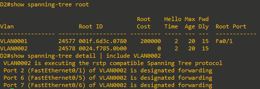
- To illustrate the behavior of Root Guard, we will configure it on a designated port on D2 for VLAN 2. D2 is the root bridge for VLAN 2, so all trunk ports are designated, as shown in the following outputs.

- Go to A1 and verify what the root port for VLAN0002. It should be interface G0/4 because of the change in port priority we configured earlier on D2.

-
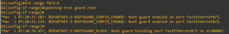
Now on D2, add root guard to the ports connected to A1.

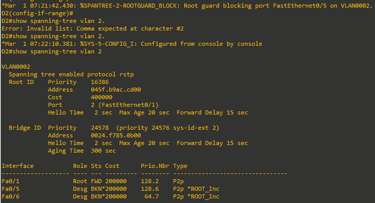
- To verify that root guard is working, try to have A1 take over as root bridge for VLAN0002. Issue the command spanning-tree vlan 2 priority 16384.
A1(config)# spanning-tree vlan 2 priority 16384 -
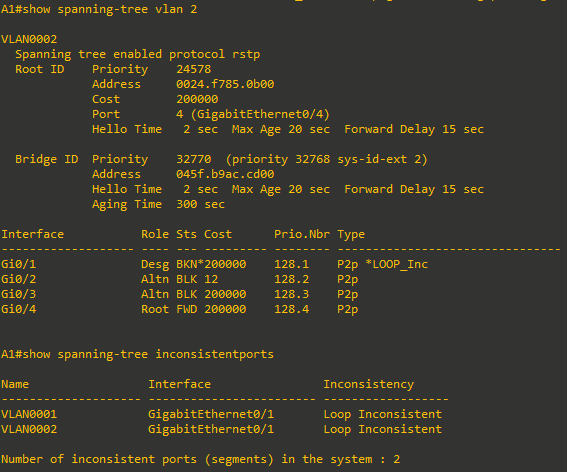
Return to D1 and issue the command show spanning-tree vlan 2.

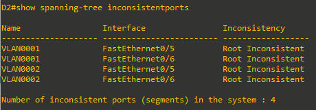
This output has two indicators of the issue. First BKN* is short for “BROKEN”, and *ROOT_Inc represents the Root Inconsistent message. A list of all STP inconsistent ports including the reason for their inconsistency can also be requested with the command show spanning-tree inconsistentports.
-
To return things to normal, issue the command no spanning-tree vlan 2 priority 16384 on A1 and then remove root guard on interfaces F0/5 and F0/6 of D2 with the command no spanning-tree guard root.


Step 2: Implement and observe BPDU Guard
PortFast allows a port to immediately enter the Forwarding state, which can create switching loops if two PortFast-enabled ports are accidentally or intentionally connected. Normally, if a PortFast port receives a BPDU, it reverts to a regular spanning-tree port, but under heavy load, this may not happen quickly, increasing the risk of a loop.
BPDU Guard provides extra protection by automatically shutting down (err-disabling) any port that receives an unexpected BPDU. This feature is mainly used on PortFast-enabled ports but can be enabled globally using the spanning-tree portfast bpduguard default command (affecting all PortFast ports) or per interface using the spanning-tree bpduguard enable command (regardless of PortFast status). This ensures that if a BPDU is received, the port is immediately disabled, preventing potential loops.
For this example, we will configure BPDU guard on a trunking interface that is a non-root port on A1. Configuring BPDU Guard on an interface that is intended to be a trunk is not a recommended practice; we are doing this just to demonstrate the functionality of the tool.
-
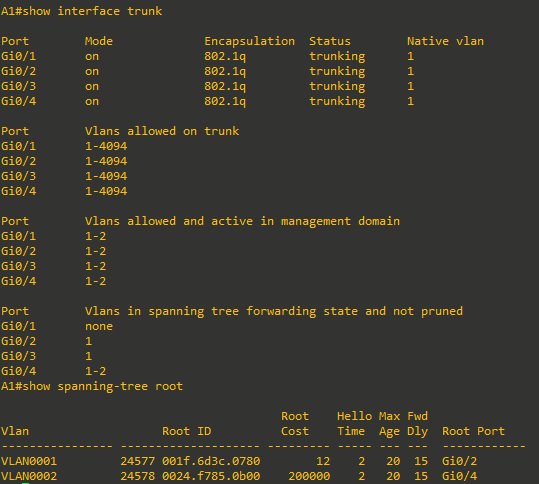
Verify the trunking ports and root ports on A1 using the commands show spanning-tree root and show interface trunk. From the output below, we see that interface G1/0/1 will meet the requirements for this demonstration (non-root trunk).
-
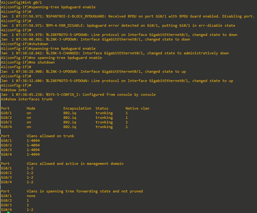
On A1 interface G0/1, issue the command spanning-tree bpduguard enable. As you can see, the interface is almost immediately err-disabled. Issue the shutdown command, remove BPDU Guard with the no spanning-tree bpduguard enable command, and then issue the no shutdown command to bring it back up. Verify the trunk is operational with the show interface trunk command.


Step 3: Implement and observe BPDU Filter
PortFast and BPDU Guard do not stop a switch from sending BPDUs on an interface. If you need to prevent BPDUs from being sent, use BPDU Filter. BPDU Filter can be set globally or per interface:
- Global BPDU Filter (spanning-tree portfast bpdufilter default): Applies only to PortFast-enabled ports. These ports send up to 11 BPDUs when they come up, then stop sending BPDUs. If the port receives a BPDU, both BPDU Filter and PortFast are disabled, and the port returns to normal spanning tree operation. Thus, global BPDU Filter mainly stops sending BPDUs but does not block receiving or processing them.
- Interface BPDU Filter (spanning-tree bpdufilter enable): When set on a specific port, the port completely stops sending and processing BPDUs. This can be used to separate a network into multiple independent STP domains, but without spanning tree protection, it is the administrator’s responsibility to ensure these domains are only connected by a single link to prevent loops.
For this demonstration, we will configure BPDU filter at the interface level.
-
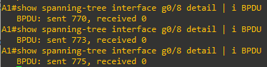
Find out how many BPDUs interface G0/8 on Switch A1 has sent using the show spanning-tree interface g0/8 detail | i BPDU command. Repeat the command several times to validate that the BPDU count is increasing.

-
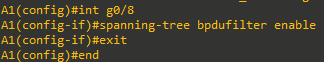
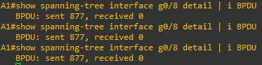
Configure the interface with BPDU filter using the spanning-tree bpdufilter enable command.
- Verify BPDUs are no longer being sent. Issue the command show spanning-tree interface g1/0/23 detail | i BPDU several times and you should see that the BPDU count is not increasing.

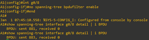
- Remove BPDU filter with the no spanning-tree bpdufilter enable command. Verify that BPDUs are now being sent.


Step 4: Implement and observe Loop Guard
Loop Guard prevents Root and Alternate ports from incorrectly becoming Designated ports if they stop receiving BPDUs. In STP, all ports, including blocked ports, listen for BPDUs to confirm the presence and status of neighboring devices. If a blocked port suddenly stops receiving BPDUs (for example, due to a unidirectional link caused by a fiber issue), it may mistakenly transition to the Forwarding state, creating a switching loop.
Loop Guard addresses this by keeping affected ports in a Loop-Inconsistent (non-forwarding) state until BPDUs are received again, preventing loops. It can be enabled globally (spanning-tree loopguard default) or per interface (spanning-tree guard loop). Loop Guard should not be used on PortFast enabled ports.
For this example, we will configure Loop Guard on an Alternate port on A1 and then stop sending out BPDUs from the corresponding Designated port on the other end of the link.
-
Verify which ports are Alternate ports for VLAN 2 on A1 using the show spanning-tree vlan 2 command.

-
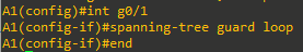
On A1, configure interface G0/1 with loop guard.

-
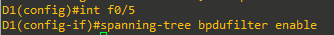
On D1, configure the port connecting to G0/1 for bpdufilter; in this topology it is interface F0/5.

-
On A1, you should receive a SYSLOG message stating that Loop Guard has blocked port G0/1. Issue the command show spanning-tree vlan 2 and you will see that G0/1 is broken. Issue the command show spanning-tree inconsistentports and you will see that G0/1 is loop-inconsistent.
-
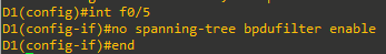
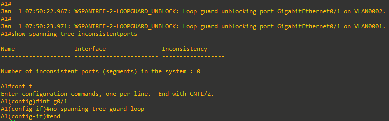
On D1, remove the BPDU filter on interface G1/0/5.

-
On A1, you should see a SYSLOG message indicating Loop Guard has removed the block on interface G1/0/1. Remove the loop guard configuration.