Lab - Implement VRF-Lite
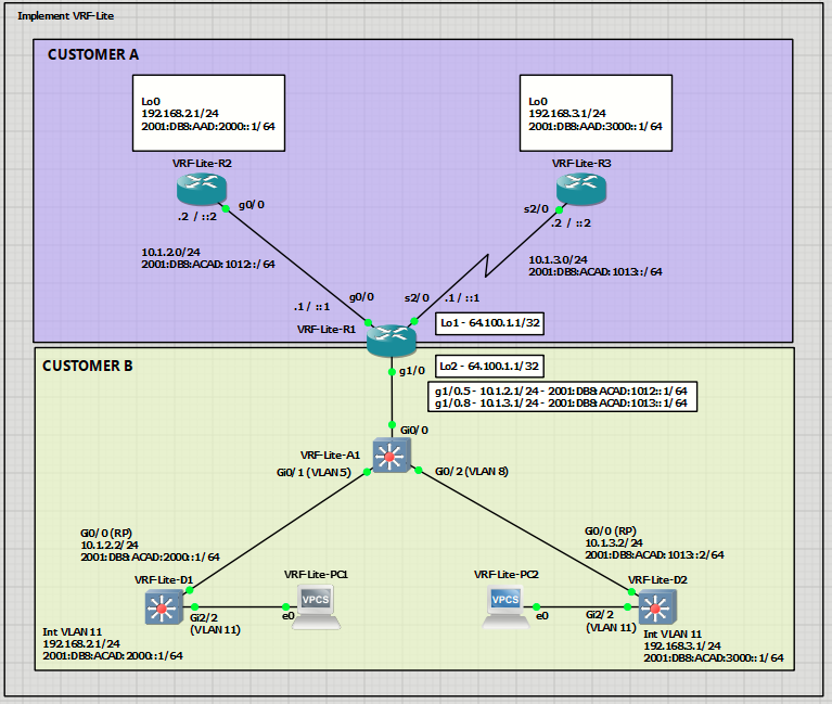
Topology
Addressing Table
| Device | Interface | IPv4 Address | IPv6 Address | IPv6 Link-Local |
| R1 | G0/0/0 | 10.1.2.1/24 | 2001:db8:acad:1012::1/64 | fe80::1:1 |
| R1 | G0/0/1.5 | 10.1.2.1/24 | 2001:db8:acad:1012::1/64 | fe80::1:2 |
| R1 | G0/0/1.8 | 10.1.3.1/24 | 2001:db8:acad:1013::1/64 | fe80::1:4 |
| R1 | S0/1/0 | 10.1.3.1/25 | 2001:db8:acad:1013::1/64 | fe80::1:2 |
| R2 | G0/0/0 | 10.2.3.2/24 | 2001:db8:acad:1023::2/64 | fe80::2:1 |
| R2 | Loopback0 | 192.168.2.1/24 | 2001:db8:acad:2000::1/64 | fe80::2:2 |
| R3 | S0/1/0 | 10.1.3.3/25 | 2001:db8:acad:1013::3/64 | fe80::3:1 |
| R3 | Loopback0 | 192.168.3.1/27 | 2001:db8:acad:3000::1/64 | fe80::3:2 |
| D1 | G1/0/5 | 10.1.2.2/24 | 2001:db8:acad:1012::2/64 | fe80::d1:1 |
| D1 | VLAN 11 | 192.168.2.1/24 | 2001:db8:acad:2000::2/64 | fe80::d1:2 |
| D2 | G1/0/5 | 10.1.3.2/24 | 2001:db8:acad:1013::2/64 | fe80::d2:1 |
| D2 | VLAN 11 | 192.168.3.1/24 | 2001:db8:acad:3000::1/64 | fe80::d2:2 |
Objectives
- Part 1: Configure basic settings for each device.
- Part 2: Configure and Verify VRF and Interface Addressing
Part 3: Configure and Verify Dynamic Routing for Reachability Inside Each VRF
Background / Scenario
On a traditional router, all interfaces participate in a single, global routing table. That means every route learned or configured is visible to every interface, and any overlapping IP address space would immediately conflict. Service providers and large enterprises often need to virtualize a router so that it can act like multiple independent routers at once.
Virtual Routing and Forwarding (VRF) solves this by creating separate routing tables on the same device. Each table is an isolated routing instance with its own interfaces and routes. VRF-Lite delivers this capability without Multiprotocol Label Switching (MPLS) and is intended for local segmentation on a single router or a small network.
With VRF-Lite, you place interfaces into specific VRFs. Each VRF maintains its own routes, so identical prefixes can exist at the same time without interference. The router forwards based on the VRF tied to the incoming interface, which keeps customer or department traffic isolated. Traffic does not cross between VRFs by default, which prevents leakage. Reachability inside each VRF uses familiar methods such as static routes or dynamic routing protocols configured per VRF. Inter-VRF communication, if needed, must be configured
explicitly.
In this lab, you will work on R1, acting as a service provider router that supports two customers using the same addressing scheme. Your task is to deploy VRF-Lite and static routing to ensure full reachability within each customer’s network.
Note: This lab is an exercise in developing, deploying, and verifying VRF-Lite, and does not reflect networking best practices.
Required Resources - Sergio Jimenez's Version
For this lab I am using GNS3 where I have deployed:
- 3 IOSv router
- 3 IOSvL2 switches
- 2 VPCs
Instructions
Part 1: Configure basic settings for each device.
VRF-Lite-R1
hostname R1
no ip domain lookup
ipv6 unicast-routing
banner motd # R1, Implement VRF-Lite #
line con 0
exec-timeout 0 0
logging synchronous
exit
line vty 0 4
privilege level 15
password cisco123
exec-timeout 0 0
logging synchronous
login
exit
VRF-Lite-R2
hostname R2
no ip domain lookup
ipv6 unicast-routing
banner motd # R2, Implement VRF-Lite #
line con 0
exec-timeout 0 0
logging synchronous
exit
line vty 0 4
privilege level 15
password cisco123
exec-timeout 0 0
logging synchronous
login
exit
interface g0/0
ip address 10.1.2.2 255.255.255.0
ipv6 address fe80::2:1 link-local
ipv6 address 2001:db8:acad:1012::2/64
ospfv3 100 ipv6 area 0
ospfv3 100 ipv4 area 0
no shutdown
exit
interface loopback 0
ip address 192.168.2.1 255.255.255.0
ipv6 address fe80::2:2 link-local
ipv6 address 2001:db8:acad:2000::1/64
ospfv3 network point-to-point
ospfv3 100 ipv4 area 0
ospfv3 100 ipv6 area 0
no shutdown
exit
router ospfv3 100
router-id 2.2.2.2
address-family ipv4 unicast
exit-address-family
address-family ipv6 unicast
exit-address-family
VRF-Lite-R3
hostname R3
no ip domain lookup
ipv6 unicast-routing
banner motd # R3, Implement VRF-Lite #
line con 0
exec-timeout 0 0
logging synchronous
exit
line vty 0 4
privilege level 15
password cisco123
exec-timeout 0 0
logging synchronous
login
exit
interface loopback 0
ip address 192.168.3.1 255.255.255.0
ipv6 address fe80::3:2 link-local
ipv6 address 2001:db8:acad:3000::1/64
ospfv3 network point-to-point
ospfv3 100 ipv4 area 0
ospfv3 100 ipv6 area 0
no shutdown
exit
interface s2/0
ip address 10.1.3.2 255.255.255.0
ipv6 address fe80::3:1 link-local
ipv6 address 2001:db8:acad:1013::2/64
ospfv3 100 ipv4 area 0
ospfv3 100 ipv6 area 0
no shutdown
exit
router ospfv3 100
router-id 3.3.3.3
address-family ipv4 unicast
exit-address-family
address-family ipv6 unicast
exit-address-family
VRF-Lite-D1
hostname D1
no ip domain lookup
ip routing
ipv6 unicast-routing
banner motd # D1, Implement VRF-Lite #
line con 0
exec-timeout 0 0
logging synchronous
exit
line vty 0 4
privilege level 15
password cisco123
exec-timeout 0 0
logging synchronous
login
exit
interface g0/0
no switchport
ip address 10.1.2.2 255.255.255.0
ipv6 address fe80::d1:1 link-local
ipv6 address 2001:db8:acad:1012::2/64
ospfv3 200 ipv4 area 0
ospfv3 200 ipv6 area 0
no shutdown
exit
vlan 11
name LOCAL_VLAN
exit
interface vlan 11
ip address 192.168.2.1 255.255.255.0
ipv6 address fe80::d1:2 link-local
ipv6 address 2001:db8:acad:2000::1/64
ospfv3 200 ipv4 area 0
ospfv3 200 ipv6 area 0
no shutdown
exit
interface g2/2
switchport mode access
switchport access vlan 11
no shutdown
exit
router ospfv3 200
router-id 4.4.4.4
address-family ipv4 unicast
exit-address-family
address-family ipv6 unicast
exit-address-family
VRF-Lite-D2
hostname D2
no ip domain lookup
ip routing
ipv6 unicast-routing
banner motd # D2, Implement VRF-Lite #
line con 0
exec-timeout 0 0
logging synchronous
exit
line vty 0 4
privilege level 15
password cisco123
exec-timeout 0 0
logging synchronous
login
exit
interface g0/0
no switchport
ip address 10.1.3.2 255.255.255.0
ipv6 address fe80::d2:1 link-local
ipv6 address 2001:db8:acad:1013::2/64
ospfv3 200 ipv4 area 0
ospfv3 200 ipv6 area 0
no shutdown
exit
vlan 11
name LOCAL_VLAN
exit
interface vlan 11
ip address 192.168.3.1 255.255.255.0
ipv6 address fe80::d2:2 link-local
ipv6 address 2001:db8:acad:3000::1/64
ospfv3 200 ipv4 area 0
ospfv3 200 ipv6 area 0
no shutdown
exit
interface g2/2
switchport mode access
switchport access vlan 11
no shutdown
exit
router ospfv3 200
router-id 5.5.5.5
address-family ipv4 unicast
exit-address-family
address-family ipv6 unicast
exit-address-family
VRF-Lite-A1
hostname A1
no ip domain lookup
no ip routing
banner motd # A1, Implement VRF-Lite #
line con 0
exec-timeout 0 0
logging synchronous
exit
line vty 0 4
privilege level 15
password cisco123
exec-timeout 0 0
logging synchronous
login
exit
vlan 5
name D1
exit
vlan 8
name D2
exit
interface g0/0
switchport mode trunk
switchport nonegotiate
no shutdown
exit
interface g0/1
switchport mode access
switchport access vlan 5
no shutdown
exit
interface g0/2
switchport mode access
switchport access vlan 8
no shutdown
Part 2: Configure and Verify VRF and Interface Addressing
In Part 2, you will configure and verify VRF-Lite on R1. The other devices, R2, R3, D1, D2, and A1 require no additional configuration. Once again, the configuration being used here is not meant to represent best practice, but to assess your ability to complete the required configurations
Step 1: On R1, create the required VRFs.
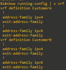
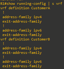
- Create the CustomerA and CustomerB VRFs, and initialize them for both IPv4 and IPv6. The VRF names are case sensitive.
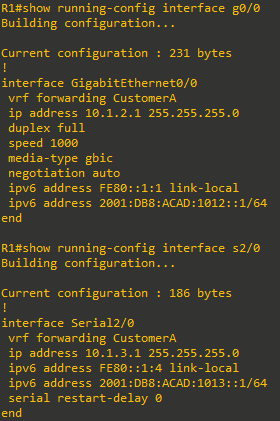
- Configure interfaces G0/0 and S2/0 for the CustomerA network.
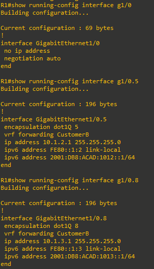
- Configure R1 interface G1/0 to support the CustomerB networks. G1/0 will be performing inter-VLAN routing between VLANs 5 and 8.
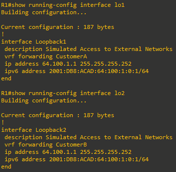
- Configure loopback interfaces on R1 to simulate access to external networks
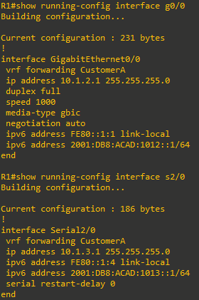
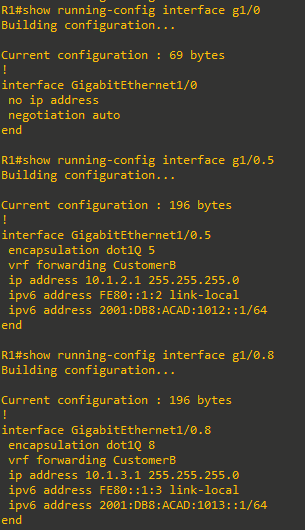
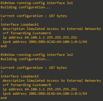
Step 2: Verify the VRF-Lite configuration.
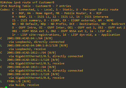
- Verify the routing and forwarding information.
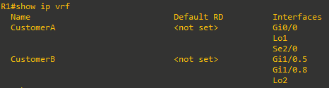
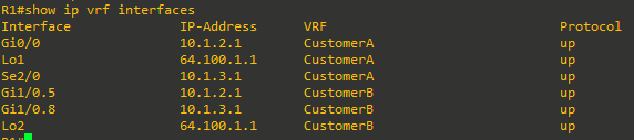
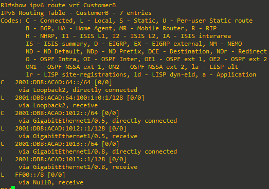
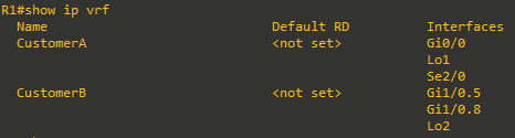
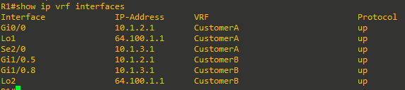
- Verify the interface assignments using the show ip vrf interfaces command.
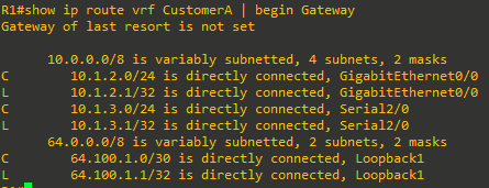
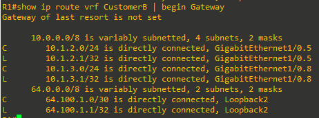
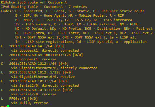
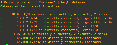
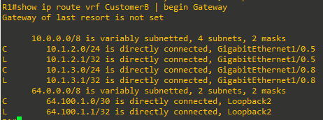
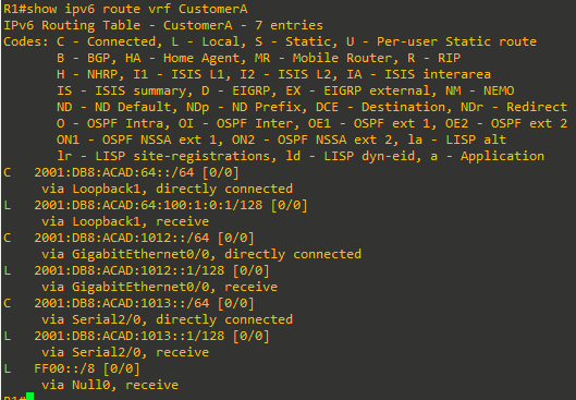
- Verify the VRF routing tables with the show ip route vrf vrf_name and show ipv6 route vrf vrf_name
command
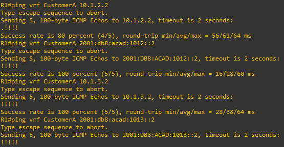
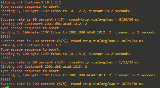
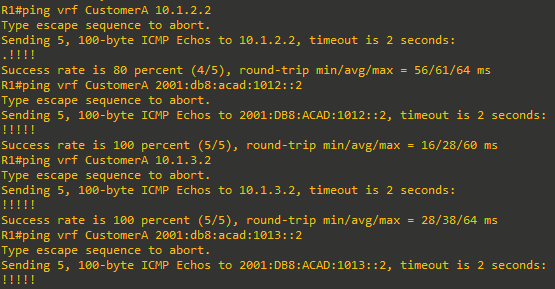
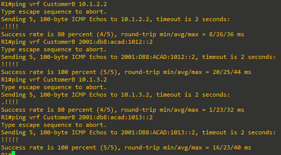
- Verify next-hop reachability within each vrf with the ping vrf vrf_name address command
Part 3: Configure and Verify Dynamic Routing for Reachability Inside Each VRF
In Part 3, you will configure OSFP so that all networks are reachable within their respective VRFs. At the end of this part, R1 should be able to successfully source a ping from interface loopback0 to R3 interface Loopback0, and D1 should be able to successfully source a ping from interface VLAN 11 to D2 interface VLAN 11. Furthermore, you will configure a default route to access an external network simulated the loopback interfaces. Once again, the way these networks are being implemented is not meant to represent best practice, but to assess your ability to complete the required configurations.
Step 1: Verify that distant networks are not reachable within each VRF.
In this step, you will check to make sure that distant networks are not reachable from R1 within each VRF.
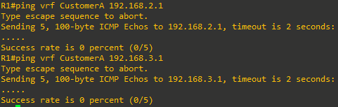
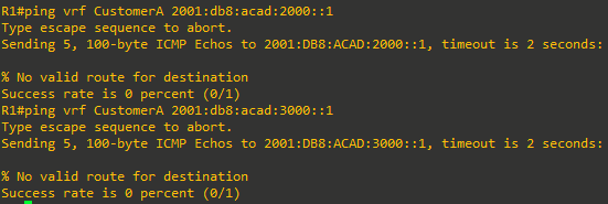
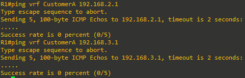
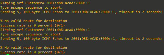
- On R1, issue the commands ping vrf CustomerA 192.168.2.1 and ping vrf CustomerA 192.168.3.1. Neither should succeed.
- On R1, issue the commands ping vrf CustomerA 2001:db8:acad:2000::1 and ping vrf CustomerA 2001:db8:acad:3000::1. Neither should succeed.
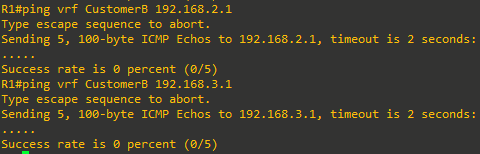
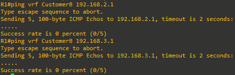
- On R1, issue the commands ping vrf CustomerB 192.168.2.1 and ping vrf CustomerB 192.168.3.1. Neither should succeed.
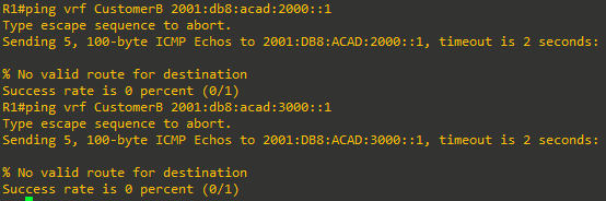
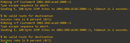
- On R1, issue the commands ping vrf CustomerB 2001:db8:acad:2000::1 and ping vrf CustomerB 2001:db8:acad:3000::1. Neither should succeed.
Step 2: Configure OSFP at R1 for each VRF.
In this step, you will configure R1 so that it can reach distant networks in each VRF. The neighbor systems (D1, D2, R2, and R3) have OSPF routes already configured, so as soon as you correctly install these dynamic routes, there will be full reachability within each VRF.
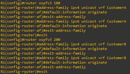
- On R1, configure OSPF routes for the distant networks in the CustomerA VRF using OSPFv3.
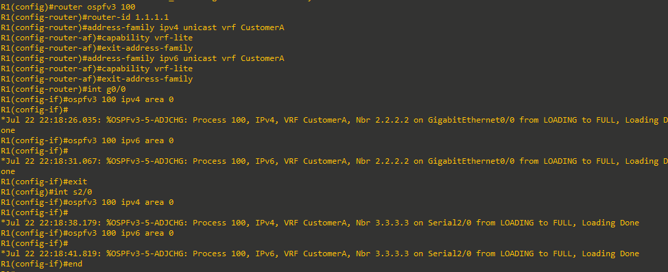
- Use the example above to correctly configure the OSPF routes for the CustomerB network.
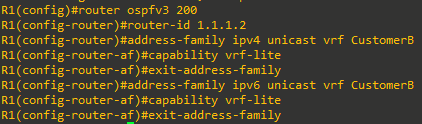
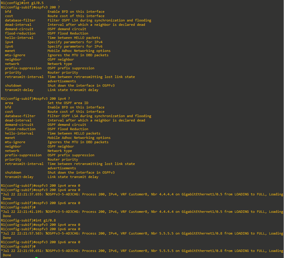
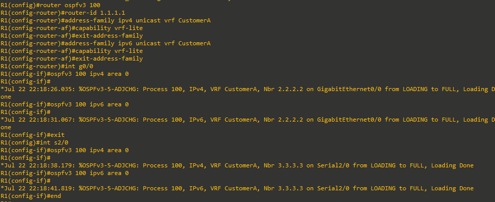
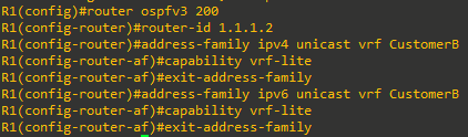
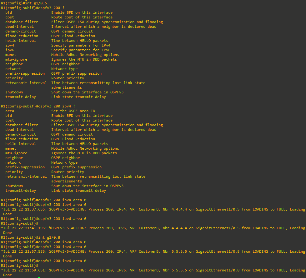
Step 3: Verify OSPF routes.
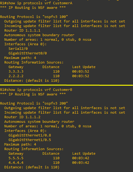
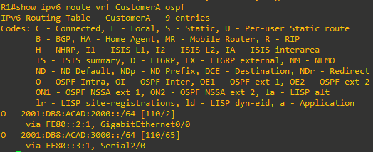
- On R1, verify the OSPF routes in routing table for CustomerA.

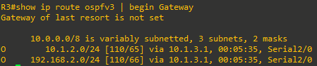
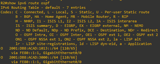
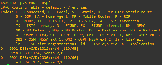
- On R2 and R3, display and verify the OSPF routes in the routing table.


- Verify the OSPF routes for CustomerB.



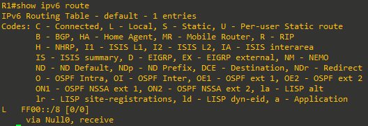
- Repeat the above steps for IPv6 OSPF routes.
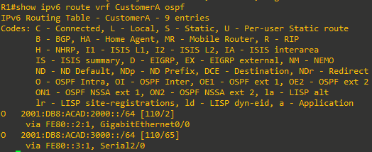
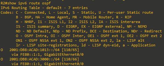
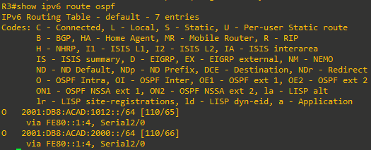
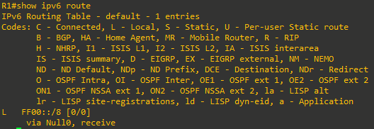
- Because all the interfaces are participating in the VRF, there are no routes in global routing table.







Step 4: Verify full reachability within each VRF.
- On R2, ping the IPv4 and IPv6 addresses of R3 interface Loopback0 using a source address of R2 interface Loopback0. All pings should be successful.


- On D1, ping the IPv4 and IPv6 addresses of D2 interface VLAN 11 using a source address of D1 interface VLAN 11. All pings should be successful.






Step 5: Configure and distribute default route for each VRF.
In this step, you will configure default routes on R1 and advertise the default routes into each VRF so that the devices in each VRF can reach distant networks simulated by the loopback interfaces on R1.
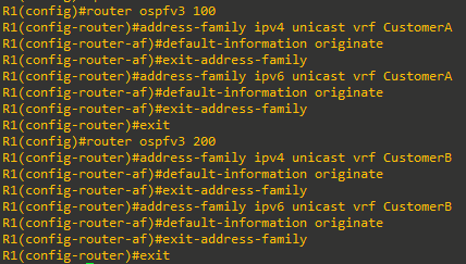
- On R1, configure the default routes for each VRF.

- Advertise the default routes into the OSPF process 100 and 200 so each VRF member learns the default routes.
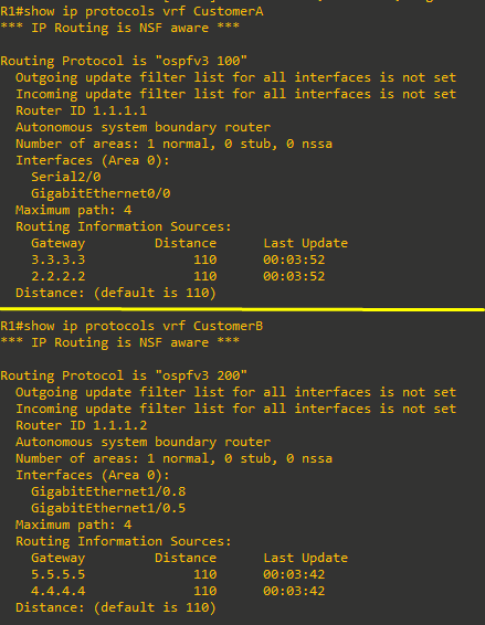
- Verify that default routes have been advertised with each VRF.




- Review the routing protocol parameters and statistics for each VRF.
- Verify that R2, R3, D1 and D2 can ping the simulated access to the external network.