Lab - Implement NTP
Topology
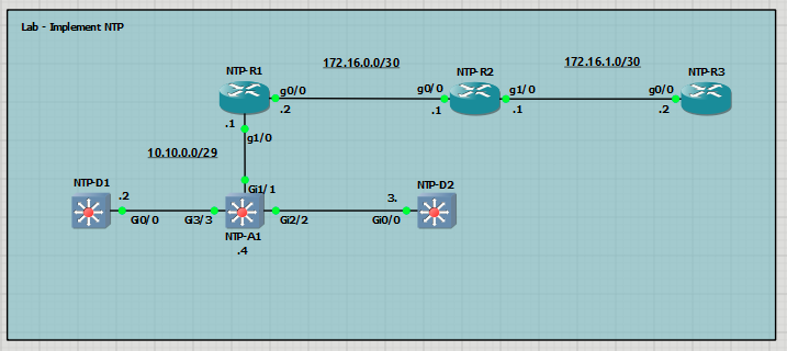
Addressing Table
| Device | Interface | IPv4 Address |
| R1 | G0/0/0 | 172.16.0.2/30 |
| G0/0/1 | 10.10.0.1/29 | |
| R2 | G0/0/0 | 172.16.0.1/30 |
| G0/0/1 | 172.16.1.1/30 | |
| R3 | G0/0/0 | 172.16.1.2/30 |
| D1 | G1/0/5 | 10.10.0.2/29 |
| D2 | G1/0/5 | 10.10.0.3/29 |
| A1 | VLAN 1 | 10.10.0.4/29 |
Objectives
- Part 1: Build the Network, Configure Basic Device Settings and Routing
- Part 2: Configure NTP in a P2P Network
- Part 3: Configure NTP in a Multiaccess Broadcast Network
Background / Scenario
Accurate and synchronized time is crucial for the efficient operation of network devices, enabling effective troubleshooting, precise Syslog and SNMP event reporting, and the correlation of security events across multiple systems. While devices use either software clocks (which reset on reboot) or hardware clocks (which retain time), neither inherently provides synchronization across the network. Network Time Protocol (NTP) offers a scalable solution by synchronizing device clocks through a hierarchical architecture, where clients
periodically poll authoritative NTP servers, using multiple messages to ensure high accuracy.
Note: NTP uses UDP port 123 and is documented in RFC 1305. Current versions include NTPv3 and NTPv4.
NTP is commonly implemented in three ways depending on the network type:
- Point-to-point (P2P) - Consists of an NTP server (master) and NTP client.
- Broadcast - Consists of an NTP server broadcasting (i.e., multicasting) to listening NTP broadcast clients. The server is configured using the ntp broadcast interface command and clients are configured using the ntp broadcast client interface command.
- NTP Peers - Used in larger redundant topologies for backup purposes where two NTP servers are also peers to query different external time sources. The peers establish a client server relationship with each other and try to offer their clock settings to each other. NTP peers are configured using the ntp peer peer-ip-address global config command.
In this lab, you will configure NTP as follows:
- R3 will be the designated authoritative time source.
- R2 and R3 will establish a P2P client-server NTP connection while R1 and R2 will establish a P2P client-server NTP connection.
- R1 will be configured as an NTP broadcast server to the NTP broadcast clients (i.e., A1, D1, and D2).
Note: This lab is an exercise in developing, deploying, and verifying how NTP operates and does not reflect networking best practices.
Required Resources - Sergio Jimenez's Version
For this lab I am using GNS3 where I have deployed:
- 3 C7200 Dynamips routers
- 3 IOSvL2 15.2 switches
Instructions
Part 1: Configure basic settings for the routers and switches and verify end-to-end connectivity
NTP-R1
hostname R1
no ip domain lookup
line con 0
logging sync
exec-time 0 0
exit
banner motd # This is R1, Implement NTP Lab #
interface g0/0
ip add 172.16.0.2 255.255.255.252
ip ospf 123 area 0
no shut
exit
interface g1/0
ip address 10.10.0.1 255.255.255.248
ip ospf 123 area 0
no shut
exit
NTP-R2
hostname R2
no ip domain lookup
line con 0
logging sync
exec-time 0 0
exit
banner motd # This is R2, Implement NTP Lab #
interface g0/0
ip add 172.16.0.1 255.255.255.252
ip ospf 123 area 0
no shut
exit
interface g1/0
ip address 172.16.1.1 255.255.255.252
ip ospf 123 area 0
no shut
exit
NTP-R3
hostname R3
no ip domain lookup
line con 0
logging sync
exec-time 0 0
exit
banner motd # This is R3, Implement NTP Lab #
interface g0/0
ip address 172.16.1.2 255.255.255.252
ip ospf 123 area 0
no shut
exit
NTP-D1
hostname D1
no ip domain lookup
line con 0
exec-timeout 0 0
logging synchronous
exit
banner motd # This is D1, Implement NTP Lab #
ip routing
interface g0/0
no switchport
ip address 10.10.0.2 255.255.255.248
ip ospf 123 area 0
no shut
exit
NTP-D2
hostname D2
no ip domain lookup
line con 0
logging sync
exec-time 0 0
exit
banner motd # This is D2, Implement NTP Lab #
ip routing
interface g0/0
no switchport
ip address 10.10.0.3 255.255.255.248
ip ospf 123 area 0
no shut
exit
NTP-A1
hostname A1
no ip domain lookup
line con 0
exec-timeout 0 0
logging synchronous
exit
banner motd # This is A1, Implement NTP Lab #
interface range g1/1, g2/2, g3/3
no shutdown
interface vlan 1
ip address 10.10.0.4 255.255.255.248
no shut
exit
ip default-gateway 10.10.0.1
End-to-end connectivity verification:
From D1 to R3:

From D2 to R3:

Part 2: Configure NTP in a P2P Network
In this part, NTP will be configured for P2P. Specifically, R3 will be the authoritative server for R2, and R2 will be the server for R1.
The device selected as the authoritative time server is configured using the ntp master stratum global configuration command. The stratum variable identifies how many hops the server is away from an atomic time source.
The NTP client identifies the NTP server to associate with using the ntp server server-ip-address [prefer] [source interface-id] global configuration command. For redundancy purposes, multiple NTP servers can be specified using separate ntp server command. Use the prefer option to peer with a specific NTP server. Optionally, the source interface can be configured to stipulate the source IP address for queries for that server.
Step 1: On R3, configure the system clock.
In this lab, R3 is configured as the authoritative time source.
- Verify the system clock on R3

If they clock is correct on your device, because it has a hardware clock, assume it is not for the purposes of this step. - On R3, manually reconfigure the system clock using the clock set privileged EXEC mode command. The time you set should be the Coordinated Universal Time (UTC) value. For example, the clock is set assuming that the current UTC is 7:25 pm (i.e., 19:25). We will change the default time zone from UTC to Central European Time (CET) by specifying a +1 hours-offset. Also configure daylight savings time (CEST).

An informational message is generated stating that the system clock has been altered on the console
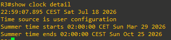
*Jul 18 20:58:00.000: %SYS-6-CLOCKUPDATE: System clock has been updated from 22:09:41 CEST Sat Jul 18 2026 to 22:58:00 CEST Sat Jul 18 2026, configured from console by console. - Verify that the system clock has been updated.



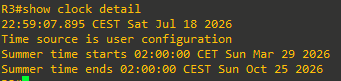
Step 2: Configure R3 to be the authoritative time source
Setting the clocks manually is not an accurate method of tracking time and events in networks. Manually configuring the time on all network devices is also not a scalable solution.
NTP enables network devices to poll an authoritative time source to ensure that all network devices are synchronized.
Time accuracy is commonly sourced from an external source, such as an atomic clock or a GPS receiver. Another option is to configure a device to be an authoritative time source. However, this command should only be used if you do not have a reliable external reference clock.
In this lab, R3 will be configured as an authoritative time source using the ntp master stratum command. The stratum number should be configured with a high number if a more reliable NTP source becomes available. When multiple NTP servers are specified, an NTP-enabled client automatically chooses the server with the lowest stratum number as its time source.
Note: The lower the stratum number the more trustworthy the accuracy of the time source.
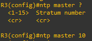
- Configure R3 as the authoritative time source with a stratum of 10 using the ntp master command.
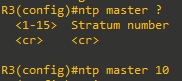
- Verify if there are any NTP clients or peers on the network using the show ntp associations command.

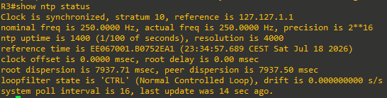
There are no other NTP clients. The address 127.127.1.1 is the loopback IP address of R3 that was assigned by the ntp master command. The reference clock is LOCL (i.e., local) with a stratum number of 9 which is one less than the configured number of 10. - Verify the status of NTP using the show ntp status command.
Because R3 is the NTP master, it is synchronized with itself (i.e., 127.127.1.1).
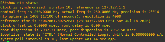
Note: It may take several minutes before the clock is synchronized with itself.

Step 3: Configure R2 to be an NTP client
In this step, R2 will acquire its time source from R3. Therefore, R2 is an NTP client and will identify the NTP server to associate with using the ntp server server-ip-address [prefer] [source interface-id] global configuration command.
Verify the system clock on R2. Configure R2 to synchronize to R3 using the ntp server server-ip-address command. The local time must be adjusted too.
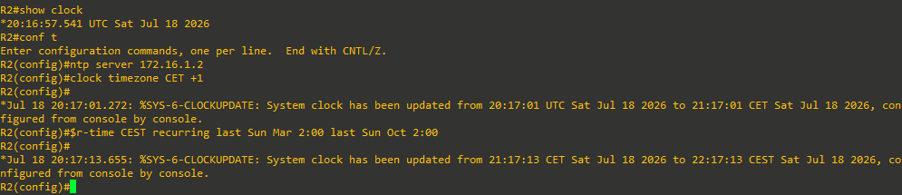
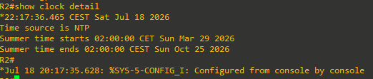
Now verify the local time on R2. Notice that the time and time zone are accurate. The output also confirms that NTP was the time source.
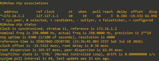
Verify if there are any NTP clients or peers on the network using the show ntp associations and show ntp status command:
Step 4: Configure R1 to be an NTP client.
In this step, R1 will become an NTP client of R2. No other configuration is required on R2 for it to advertise itself as an NTP server. However, R1 must identify R2 as its service using the ntp server command.
Verify the system clock on R1. Configure R1 to synchronize with R2 using the ntp server command. The local time zone must again be configured.
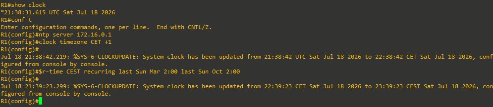
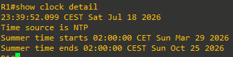
Verify the local time on R1. Notice that the time and time zone are accurate. The output also confirms that NTP was the time source.
Verify if there are any NTP clients or peers on the network using the show ntp associations command. The output confirms that R1 is a client with R2. It also identifies R3 (i.e., 172.16.1.2) which is 11 hops away as the source of R2 NTP information.
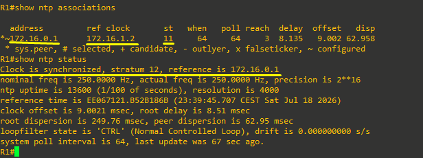
The output confirms that R1 is synchronized with R2. It now becomes a stratum 12 NTP server.
Part 3: Configure NTP in a Multiaccess Broadcast Network
In this part, NTP will be configured in a multiaccess broadcast network. Specifically, R1 will be the NTP server for the A1, D1, and D2 Ethernet clients.
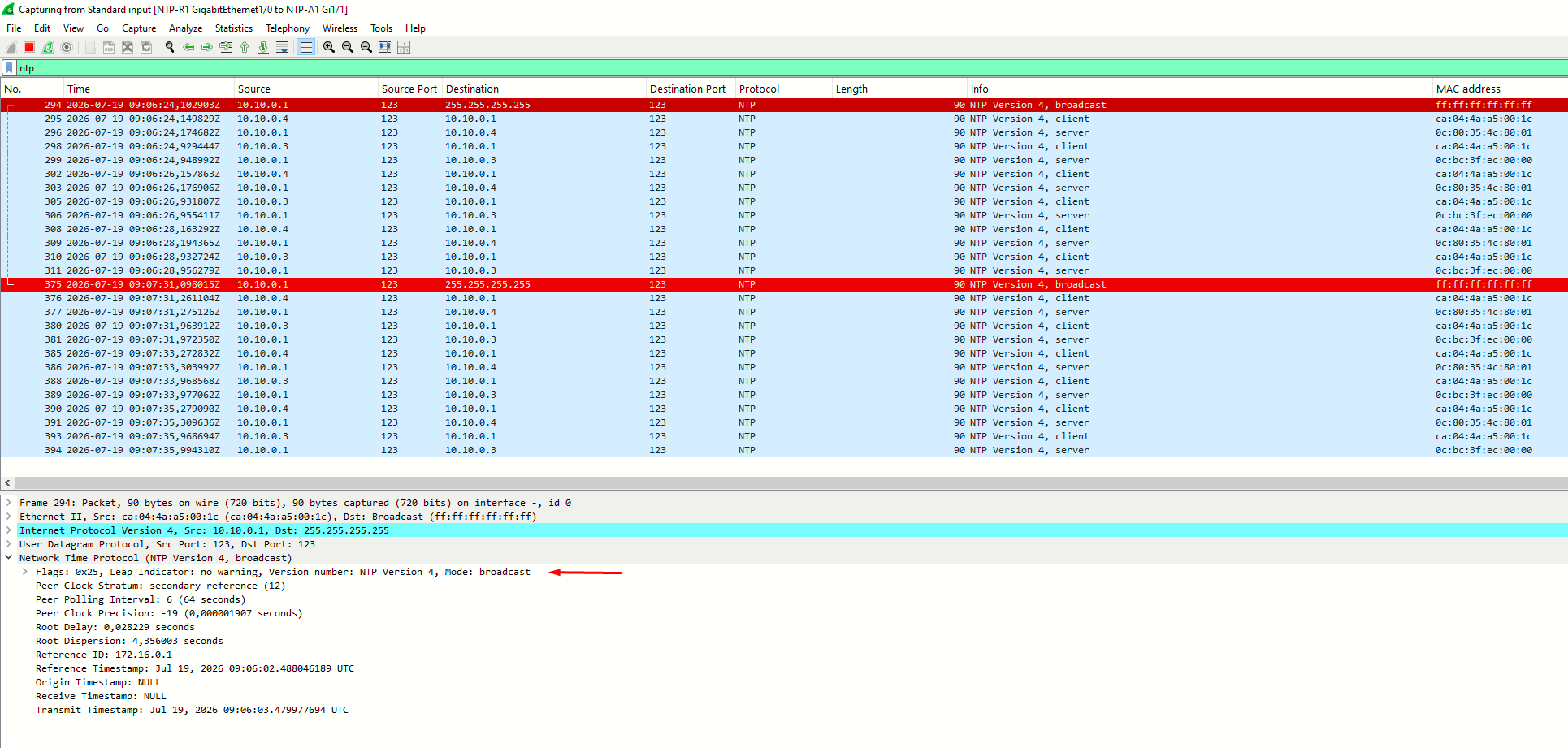
In a multiaccess network, an NTP server can broadcast (i.e., multicast) NTP updates to listening NTP broadcast clients.The NTP server Ethernet interface is configured using the ntp broadcast interface command. NTP clients are configured using the ntp broadcast client interface command.
Step 1: Configure R1 to be an NTP broadcast server
In this step, R1 will broadcast NTP advertisements to NTP clients using the ntp broadcast command on its Gi1/0 interface. Enter the Gi1/0 interface and configure R1 to be an NTP broadcast server using the ntp broadcast command.
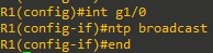
Only when configuring the Dynamips C7200 router as ntp master, does it beging sending NTP broadcasts
Step 2: Configure A1 as NTP broadcast client
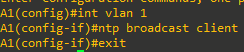
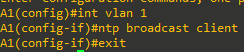
In this step, A1 will be enabled as an NTP broadcast client using the ntp broadcast client command on its management interface.
- Enter the VLAN management interface for of A1 (i.e., VLAN 1) and enable it as an NTP broadcast client.
- Configure the local time zone.

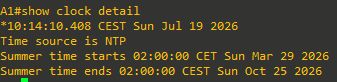
- Verify the local time on A1.
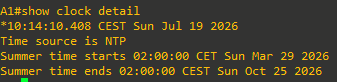
Notice that the time and time zone are accurate. The output also confirms that NTP was the source of the time. - Verify if there are any NTP clients or peers on the network using the show ntp associations command.