
Campus Distribution Layer Design
1. Traditional Distribution Layer Design
Core Concept
Uses two standalone physical switches at the distribution layer to provide resiliency, with the Layer 2 / Layer 3 boundary located at the distribution layer.
Topology Options
-
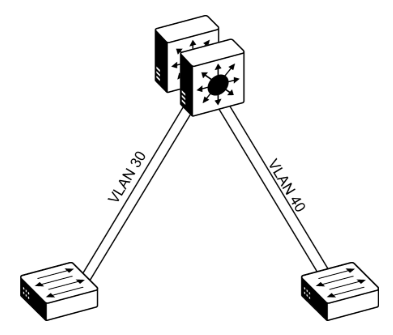
Loop-Free Design (VLAN per Access Switch):
-
Restricts each Layer 2 VLAN to a single wiring closet / access switch.
-
Eliminates topology loops and STP blocking, but limits network flexibility (VLANs cannot span across switches).
-
-
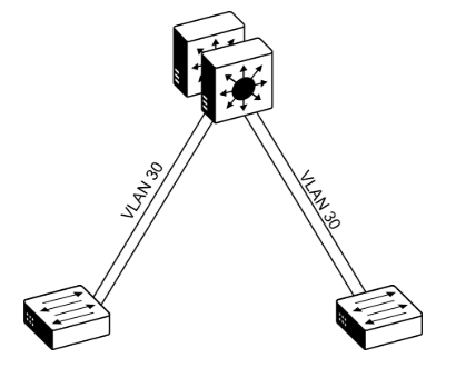
Looped Design (VLAN Spanning Access Switches):
-
Extends the same VLAN across multiple access switches to support specific applications.
-
Forces STP to block redundant links, which wastes bandwidth, risks loop failures, and causes slower convergence.
-
Default Gateway Redundancy (FHRPs)
Because the distribution switches are standalone, First-Hop Redundancy Protocols are required to provide a virtual IP/MAC gateway:
-
HSRP & VRRP: Active/Standby operation. Active traffic uses only one uplink at a time unless manually load-balanced per VLAN. Fine-tuning timers for subsecond failover increases CPU load.
-
GLBP: Balances host traffic across multiple uplinks simultaneously, but only works in non-looped topologies.
2. Simplified Distribution Layer Design
|
|
|
Core Concept
Combines multiple physical distribution switches into a single logical switch using technologies like VSS (Virtual Switching System) or Switch Stacking.
Key Features & Advantages
-
No STP Blocked Links: Uses EtherChannel (Multi-Chassis EtherChannel) for dual-homed access uplinks. All uplinks actively pass traffic and can bundle up to 8 links.
-
VLAN Flexibility: VLANs can span across multiple access switches without creating Layer 2 loops.
-
Eliminates FHRPs: HSRP, VRRP, and GLBP are no longer needed. The default gateway resides on a single logical SVI on the distribution pair.
-
Fast Failover: EtherChannel provides subsecond link failover without relying on STP timers.
-
Logical Hub-and-Spoke Topology: Simplifies troubleshooting and improves IP Multicast efficiency by providing a single logical Designated Router (DR).
-
Reduced Management Overhead: Fewer logical boxes to configure, provision, and maintain.
3. Software-Defined Access (SD-Access) Design
Core Concept
Solves Layer 2 extension and policy limits over a routed access network by deploying an automated fabric architecture.
Key Characteristics
-
Underlay vs. Overlay: Runs virtual network topologies (Overlay) over a physical Layer 3 routed network (Underlay).
-
Automated Management: Provisioned automatically using Cisco SD-Access technology.
-
Identity-Based Security: Integrates with Cisco TrustSec for software-defined micro-segmentation and policy enforcement based on user identity and group membership rather than IP address.
Quick Comparison Summary
| Feature | Traditional Design | Simplified Design | SD-Access Design |
| Distribution Setup | 2 Standalone switches | 1 Logical switch (VSS / Stack) | Fabric Control / Border Nodes |
| L2/L3 Boundary | Distribution Layer | Distribution Layer | Access Layer (Routed Access) |
| Uplink Utilization | Half blocked by STP (unless loop-free) | 100% Active via EtherChannel | 100% Active via L3 ECMP |
| Gateway Redundancy | Requires FHRP (HSRP/VRRP/GLBP) | Single Logical SVI (No FHRP) | Anycast Gateway |
| VLAN Spanning | Discouraged (causes L2 loops) | Supported seamlessly | Virtualized across fabric overlay |