Lab - Implement SNMP and Syslog
Topology
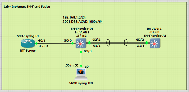
Addressing Table
| Device | Interface | IP Address | IPv6 Address | IPv6 Link Local |
| R1 | G0/0/1 | 192.168.1.1/24 | 2001:db8:acad:1000::1/64 | fe80::1:1 |
| D1 | VLAN 1 | 192.168.1.2/24 | 2001:db8:acad:1000::2/64 | fe80::d1:1 |
| A1 | VLAN 1 | 192.168.1.3/24 | 2001:db8:acad:1000::3/64 | fe80::a1:1 |
| PC1 (SNMP / Syslog service) | NIC | 192.168.1.50/24 | 2001:db8:acad:1000::50/64 | EUI-64 |
Objectives
- Part 1: Build the Network and Configure Basic Device Settings and Interface Addressing
- Part 2: Configure and Verify SNMP
- Part 3: Configure and Verify Syslog
Background / Scenario
Network Monitoring is critical to security and troubleshooting tasks. As your network grows and evolves, centralized monitoring becomes even more important. SNMP is a protocol that allows you to remotely monitor a wide range of settings and counters, be alerted when there are changes, and even remotely make configuration changes. Syslog is the log collector protocol. All of your devices should use Syslog to report device activity to a central location for correlation and records keeping. In this lab, you will configure both of these extremely important protocols.
Note: This lab is an exercise in configuring options available for SNMP and Syslog and does not necessarily
reflect network troubleshooting best practices
Required Resources - Sergio Jimenez's Version
For this lab I am using GNS3 where I have deployed:
- 1 IOSv router
- 2 IOSvL2 switches
- 1 Windows XP VM with Visual Syslog Server and SnmpB installed
Instructions
Part 1: Configure basic settings for the routers and switches and verify end-to-end connectivity
SNMP-syslog-R1
hostname R1
no ip domain lookup
ipv6 unicast-routing
banner motd # R1, Implement SNMP and Syslog #
line con 0
exec-timeout 0 0
logging synchronous
exit
line vty 0 4
privilege level 15
exec-timeout 0 0
password cisco123
login
exit
interface g0/1
ip address 192.168.1.1 255.255.255.0
ipv6 address fe80::1:1 link-local
ipv6 address 2001:db8:acad:1000::1/64
no shutdown
exit
ntp master 3
end
SNMP-syslog-D1
hostname D1
no ip domain lookup
ipv6 unicast-routing
banner motd # D1, Implement SNMP and Syslog #
line con 0
exec-timeout 0 0
logging synchronous
exit
line vty 0 4
privilege level 15
exec-timeout 0 0
password cisco123
login
exit
interface vlan 1
ip address 192.168.1.2 255.255.255.0
ipv6 address fe80::d1:1 link-local
ipv6 address 2001:db8:acad:1000::2/64
no shutdown
exit
interface g3/3
spanning-tree portfast
switchport mode access
no shutdown
exit
interface g0/0
spanning-tree portfast
switchport mode access
no shutdown
exit
interface range g1/1,g2/2
switchport mode trunk
channel-group 1 mode active
no shutdown
exit
ntp server 192.168.1.1
end
SNMP-syslog-A1
hostname A1
no ip routing
no ip domain lookup
ipv6 unicast-routing
banner motd # A1, Implement SNMP and Syslog #
line con 0
exec-timeout 0 0
logging synchronous
exit
line vty 0 4
privilege level 15
exec-timeout 0 0
password cisco123
login
exit
interface vlan 1
ip address 192.168.1.3 255.255.255.0
ipv6 address fe80::a1:1 link-local
ipv6 address 2001:db8:acad:1000::3/64
no shutdown
exit
ip default-gateway 192.168.1.1
interface range g1/1,g2/2
switchport trunk encapsulation dot1q
switchport mode trunk
channel-group 1 mode active
no shutdown
exit
ntp server 192.168.1.1
end
End-to-end connectivity verification:
From A1 to XP:

From R1 to XP:

Part 2: Configure and Verify SNMP
The Simple Network Management Protocol (SNMP) is an application layer protocol that facilitates the exchange of management information between an agent and a management server. SNMP enables network administrators to monitor and manage network performance, find and solve network problems, and plan for network growth. SNMP management workstations can ask (get) for the value of a specific object identifier (OID) from the management information base (MIB) maintained by SNMP agents. The Manager can also configure (set) specific variable values in an OID. Additionally, the agent can send notifications (traps or informs) when an event occurs, or threshold is reached (an inform is a trap that must be acknowledged by the manager). Like any powerful tool, SNMP can be dangerous if not used properly, and securing the protocol and its uses are critical.
There are three SNMP versions. SNMPv3 is considered the most secure because it offers authentication and encryption, where SNMP versions 1 and 2 offer neither. SNMP access can also be limited using an access control list. SNMPv3 is rather complex to configure, and adoption is not universal. For this lab, we will configure SNMPv2c.
Step 1: Configure access-lists for SNMP
Configure an access list on each device. This ACL will be used to specify exactly where SNMP get and set messages should be coming from. In this lab, the 192.168.1.0/24 network is the management network, and the SNMP manager is located at 192.168.1.50. Configure this ACL on all three devices:
|
|
|
|



Step 2: Configure general SNMP information.
Configure general values to identify the device, its location, and a point of contact. Configure this with appropriate values on all three devices:
|
|
|
|



Step 3: Configure SNMP community string.
SNMPv2c uses a community string-based authentication. Access can be limited further by using an access list. Create a read-only community named CCNP that is limited by the NMS-SERVER ACL. Configure this on all three devices:
|
|
|
|



Step 4: Configure SNMP trap receiver.
Configure the NMS server that traps will be sent to. As a part of this command, specific traps or sets of traps to send can be specified. If no traps are specified, this receiver will be forwarded to all traps that are enabled. This particular configuration needs to be coordinated with the network management system and network monitoring requirements for the organization.
Configure 192.168.1.50 as a trap receiver using SNMPv2c and the community CCNP. Configure this on all three devices:
|
|
|
|



Step 5: Configure interface index persistence.
Network monitoring systems record throughput and other interface statistics using SNMP polling. Each interface is referenced by its unique index number, which is dynamically assigned by the IOS during bootup. The index of each interface can be determined with the command show snmp mib ifmib ifindex. The dynamic assignment aspect of this can be problematic for documentation. Therefore, it is a good idea to instruct the system to keep a persistent list of interfaces, rather than a dynamic one. The use of this command creates a file stored in NVRAM. Configure this on all three devices:
|
|
|
|



Step 6: Run Wireshark on PC1.
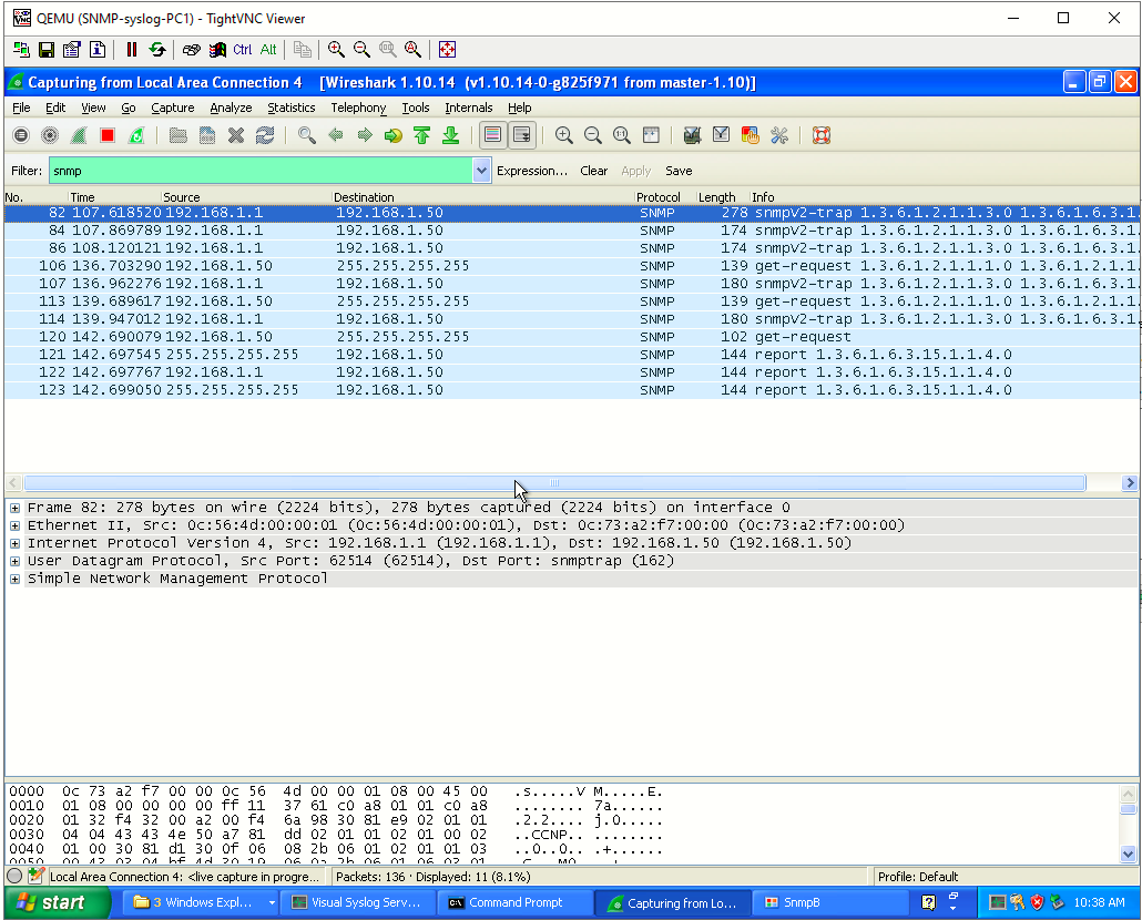
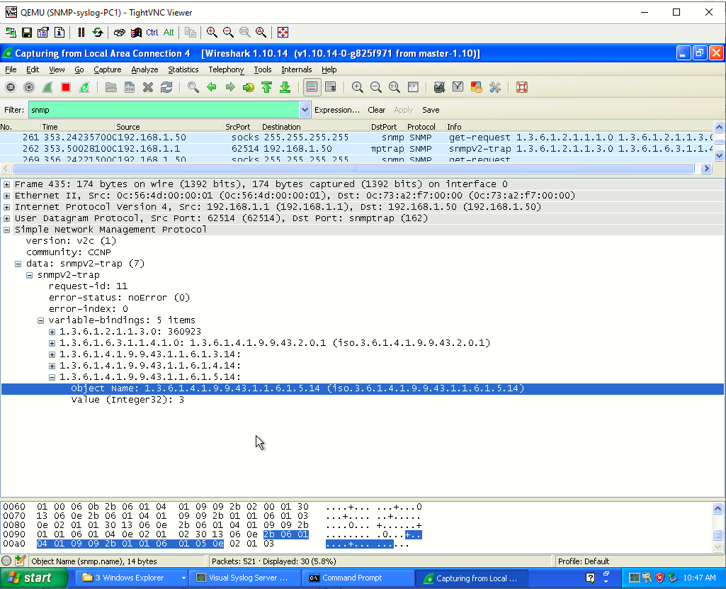
Before enabling traps to be sent, run Wireshark or another packet capture utility on PC1 and filter the output to display only SNMP packets. This ensures that the packets are actually getting to the SNMP management server
Step 7: Enable SNMP trap sending.
This final command actually enables the forwarding of traps to the configured trap receivers. As a part of this command, traps can be limited (as they can be in the snmp-server host command). Coordinate this with the network management system and network monitoring requirements for the organization. For this lab, you will simply enable all traps to be sent. Configure this on all three devices:
|
|
|
|



Step 8: Verify SNMP configuration
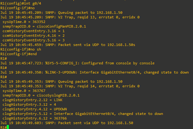
To verify that traps are being sent, issue the command debug snmp packets and then enter and exit configuration mode on each device. You should see debug output indicating that a packet was sent each time. It might take a few minutes for each device to start sending traps.
 |
|
|
|
|
|
|
|
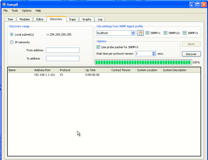
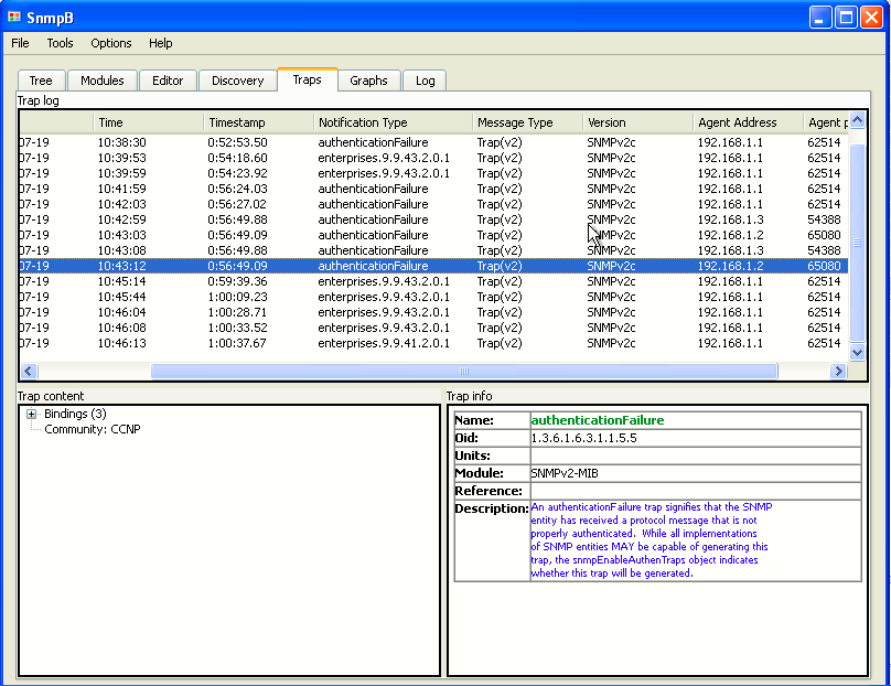
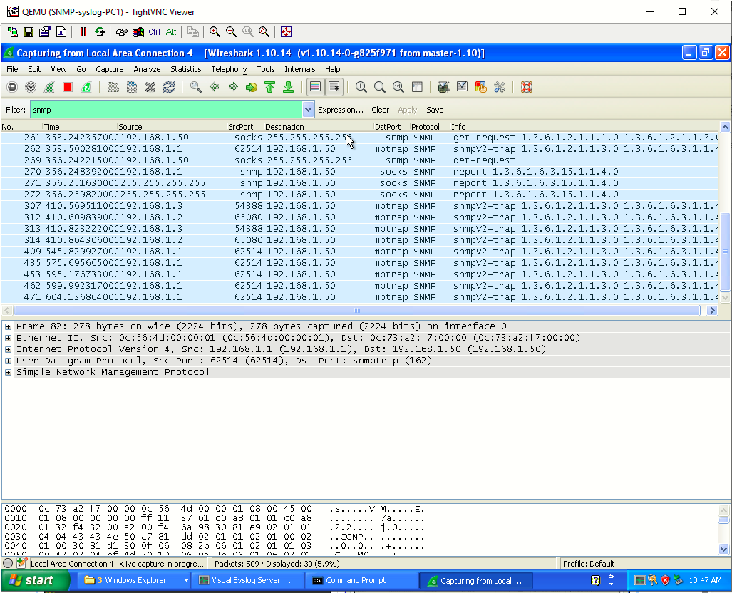
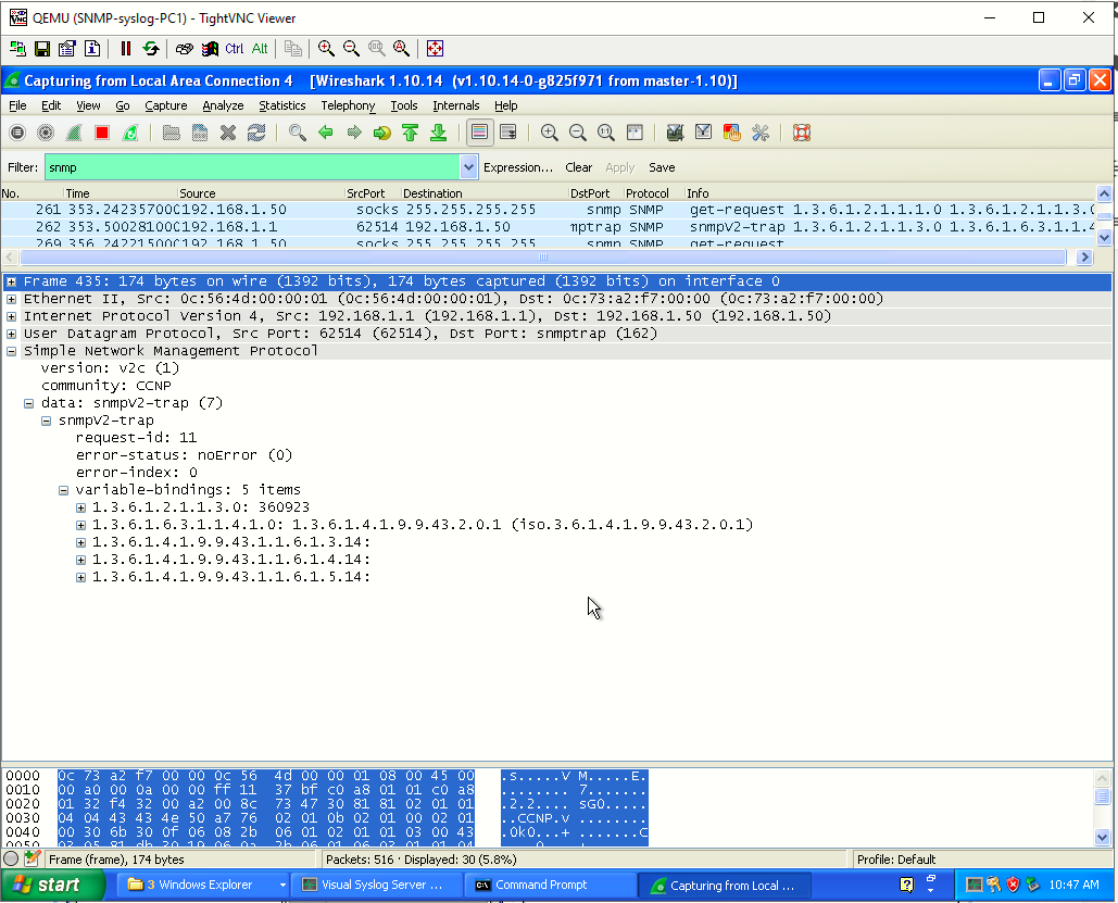
Part 3: Configure and Verify Syslog
For a multitude of reasons, logging is a critical part of your network management plan. Cisco devices log to three general facilities: the console, the logging buffer, and a syslog server, if configured. All three of these can be controlled and configured so that the type of log message they record is specific. You have already experienced console logging simply by viewing the messages the device shows you when something happens. The logging buffer has also been collecting that same information. Both of these are local to the device. What you have not done yet is customize those facilities, nor have you configured and used a centralized syslog server, which would collect log messages from each of your devices and keep them so that you can examine and correlate events between different devices.
Before configuring logging, it is important that your devices have synchronized with an NTP server, so that they are all on the same time. This makes sorting and correlating events possible.
You also must have some kind of plan of how to separate and manage the log messages. Your plan must answer the questions “What do we do with all these logs?” and “What messages go where?”
Syslog messages are separated into eight different severity levels, numbered 0 through 7. The lower numbers indicate a more critical message. The severity levels also have keywords:
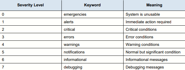
Note: When you designate a particular severity number as the specific message you want to log, you get that and anything with a smaller severity number. For example, if you set the level to 4, or use the keyword warnings, you capture messages with severity levels 4, 3, 2, 1, and 0. Before we start configuring logging, let’s look at how logging is configured by default.
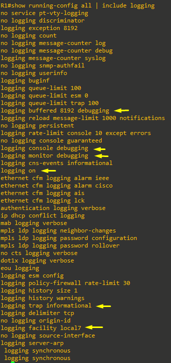
Focusing on the lines in the output that are highlighted, we see that the router is configured to send debugging (or level 7) messages to the console, monitor, and buffer. We further see that logging is turned on, and that the trap logging level is informational (or level 6), and that the logging facility is number 7. The logging trap and logging facility commands have to deal with what messages are sent to an external server and how the server routes the log messages when they are received (Log facility 7 indicates one of several custom logging facilities, which are typically tied to a specific file).
Step 1: Modify buffered logging
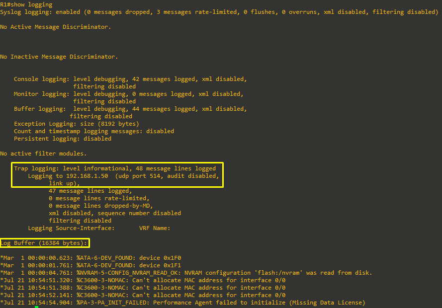
The logging buffer is set to hold 4096 bytes in a circular buffer and keep log messages at the debugging level and below. 4096 bytes is not quite enough space for a busy system, so you need to change the log buffer size to something larger. We will not be sending debugging messages to the syslog server, so the buffer is the only place those messages are stored. We will leave the logging buffer level at debugging for now and set the size of the buffer to 16384 bytes. Configure this on all three devices.

Step 2: Modify the logging trap level.
The default logging trap level is 7 (keyword: debugging), and we do not really want debug messages in the logs that we will have to archive, so we need to change the logging trap level to 6 (keyword: informational). Configure this on all three devices.

Step 3: Configure the syslog server
Next you need to configure the host address for the syslog server. In this lab, the Syslog server is 192.168.1.50. You should get a message saying logging to 192.168.1.50 has started. Configure this on all three devices:

Step 4: Verify the device configuration.
Check the device configuration by issuing the command show logging at the privileged exec prompt.
Now go to PC1 and reset Wireshark (if you have not already) and change the filter from snmp to syslog. Go into and out of configuration mode on each device, and you should see syslog messages in Wireshark: