Lab - Implement IPv4 ACLs
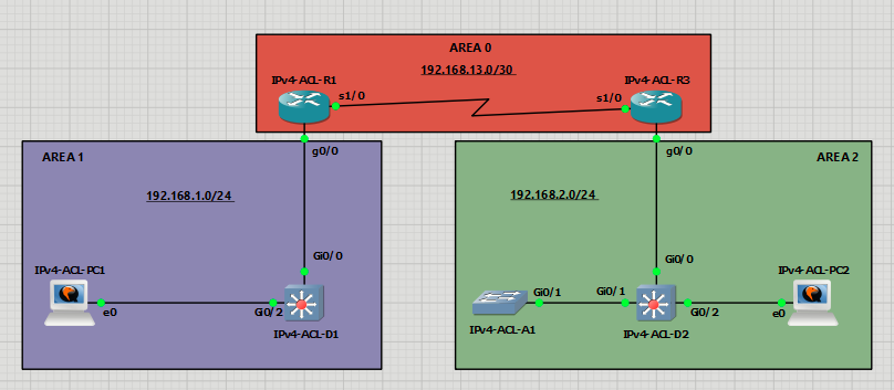
Topology
Addressing Table
| Device | Interface | IP Address | Subnet Mask | Default Gateway |
| R1 | S0/1/0 | 192.168.13.1 | 255.255.255.252 | N/A |
| G0/0/1 | 192.168.1.1 | 255.255.255.0 | ||
| R3 | S0/1/0 | 192.168.13.2 | 255.255.255.252 | N/A |
| G0/0/1 | 192.168.2.1 | 255.255.255.0 | ||
| Loopback0 | 192.168.3.1 | 255.255.255.0 | ||
| D1 | VLAN 1 | 192.168.1.2 | 255.255.255.0 | N/A |
| D2 | VLAN 1 | 192.168.2.2 | 255.255.255.0 | N/A |
| A1 | VLAN 1 | 192.168.2.3 | 255.255.255.0 | N/A |
| PC1 | NIC | 192.168.1.10 | 255.255.255.0 | 192.168.1.1 |
| PC2 | NIC | 192.168.2.10 | 255.255.255.0 | 192.168.2.1 |
Objectives
- Part 1: Build the Network and Configure Basic Device Settings
- Part 2: Verify Initial Connectivity
- Part 3: Implement Standard ACLs on R3
- Part 4: Implement a Named Extended ACL from Area 1 to Area 2
- Part 6: Implement a Port ACL on D2
- Part 7: Implement a VLAN ACL on D2
Background / Scenario
Access control lists (ACLs) are processed top-down, applying the action of the first matching entry and stopping further evaluation, with an implicit deny at the end for unmatched packets. ACLs are also used for packet classification in services like quality of service (QoS), Network Address Translations (NAT), and numerous other services.
In this lab, you will configure three different types of ACLs. Router ACLs (RACLs) are the most common type and are IP-based ACLs applied to routed interfaces. Port-based ACLs (PACLs) are applied to individual ports inside a VLAN; they are Layer 2 switchport access lists that operate inbound, using standard or extended ACLs, and are processed before VLAN ACLs and router ACLs. VLAN ACLs (VACLs), on the other hand, apply to traffic entering and leaving a VLAN and can filter traffic based on MAC addresses, IP addresses, and
port numbers. The focus of this lab is using IPv4 ACLs for packet filtering.
Note: This lab is an exercise in configuring various types of access control lists and does not necessarily reflect network troubleshooting best practices.
Required Resources - Sergio Jimenez's Version
For this lab I am using GNS3 where I have deployed:
- 2 IOSv 15.9(3)M9 routers
- 3 IOSvL2 15.2 switches
- 2 Windows XP VPC
Instructions
Part 1: Configure basic settings for the routers and switches
IPv4-ACL-R1
hostname R1
no ip domain lookup
username admin privilege 15 algorithm-type scrypt secret cisco123
banner motd # R1, Lab Access Control Lists #
line con 0
exec-timeout 0 0
logging synchronous
exit
interface g0/0
ip address 192.168.1.1 255.255.255.0
no shutdown
exit
interface s1/0
ip address 192.168.13.1 255.255.255.252
no shutdown
exit
router ospf 1
 router-id 0.0.0.1
 network 192.168.1.0 0.0.0.255 area 1
 network 192.168.13.0 0.0.0.3 area 0
 exit
line vty 0 4
login local
transport input telnet
end
IPv4-ACL-R3
hostname R3
no ip domain lookup
username admin privilege 15 algorithm-type scrypt secret cisco123
banner motd # R3, Lab Access Control Lists #
line con 0
exec-timeout 0 0
logging synchronous
exit
interface Loopback0
ip address 192.168.3.1 255.255.255.0
exit
interface g0/0
ip address 192.168.2.1 255.255.255.0
no shutdown
exit
interface s1/0
ip address 192.168.13.2 255.255.255.252
no shutdown
exit
router ospf 1
 router-id 0.0.0.3
 network 192.168.2.0 0.0.0.255 area 2
 network 192.168.3.0 0.0.0.255 area 0
 network 192.168.13.0 0.0.0.3 area 0
 exit
line vty 0 4
login local
transport input telnet
end
IPv4-ACL-D1
hostname D1
no ip routing
no ip domain lookup
username admin privilege 15 algorithm-type scrypt secret cisco123
banner motd # D1, Lab Access Control Lists #
line con 0
exec-timeout 0 0
logging synchronous
exit
interface range g0/0, g0/2
switchport mode access
no shutdown
exit
interface vlan 1
ip address 192.168.1.2 255.255.255.0
no shut
exit
ip default-gateway 192.168.1.1
line vty 0 15
login local
transport input telnet
end
IPv4-ACL-D2
hostname D2
no ip routing
no ip domain lookup
username admin privilege 15 algorithm-type scrypt secret cisco123
banner motd # D2, Lab Access Control Lists #
line con 0
exec-timeout 0 0
logging synchronous
exit
interface range g0/1-2
switchport mode access
no shutdown
exit
interface vlan 1
ip address 192.168.2.2 255.255.255.0
no shut
exit
ip default-gateway 192.168.2.1
line vty 0 15
login local
transport input telnet
end
IPv4-ACL-A1
hostname A1
no ip routing
ip ssh version 2
crypto key generate rsa modulus 2048
no ip domain lookup
username admin privilege 15 algorithm-type scrypt secret cisco123
ip http authentication local
ip http secure-server
ip domain name CCNP.ACL.LAB
banner motd # A1, Lab Access Control Lists #
spanning-tree mode rapid-pvst
line con 0
exec-timeout 0 0
logging synchronous
exit
line vty 0 15
login local
transport input telnet ssh
exec-timeout 0 0
logging synchronous
interface g0/1
switchport mode access
no shutdown
exit
interface vlan 1
ip address 192.168.2.3 255.255.255.0
no shut
ip default-gateway 192.168.2.1
exit
end
Verify ICMP connectivity between all devices and PCs.
|
|
|
Part 2: Verify Initial Connectivity
It is always advisable to test network connectivity and services before applying ACL filtering. This ensures that the network is fully functional, and that the loss of connectivity or functionality is due to the applied ACLs and not a pre-existing network issue.
When testing TCP connectivity some services will prompt for a username/password. The pre-configured username is admin and password is cisco123.
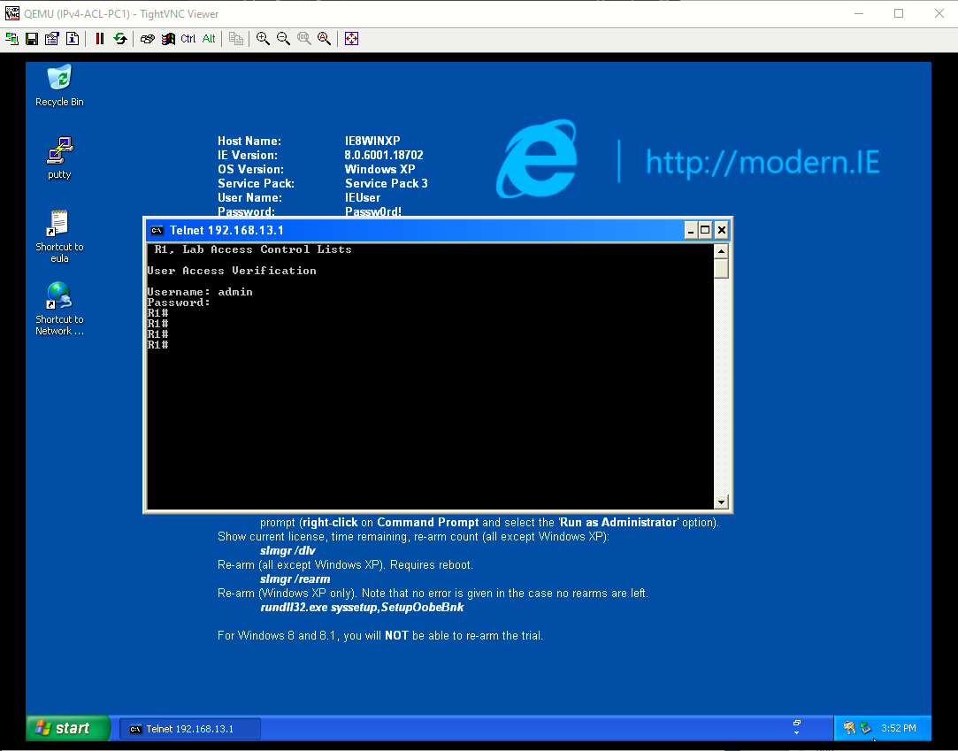
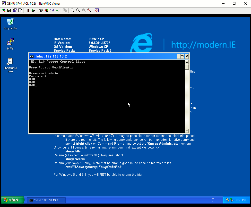
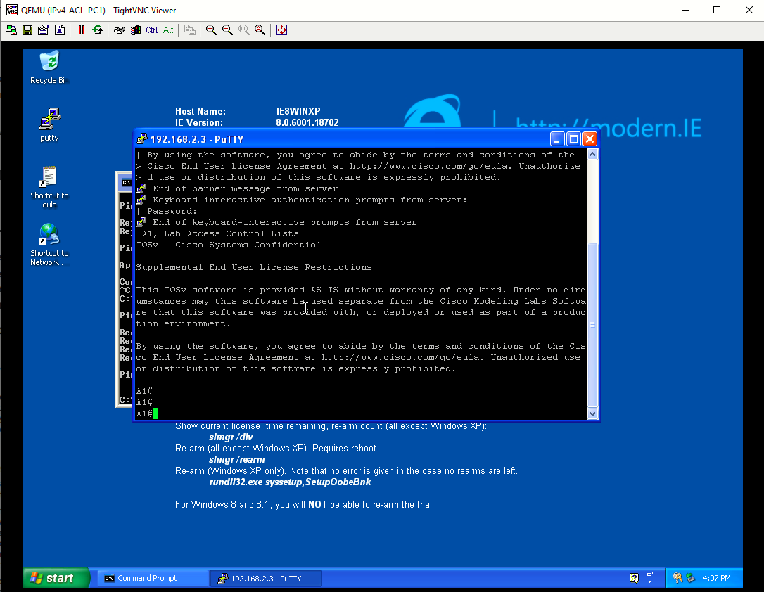
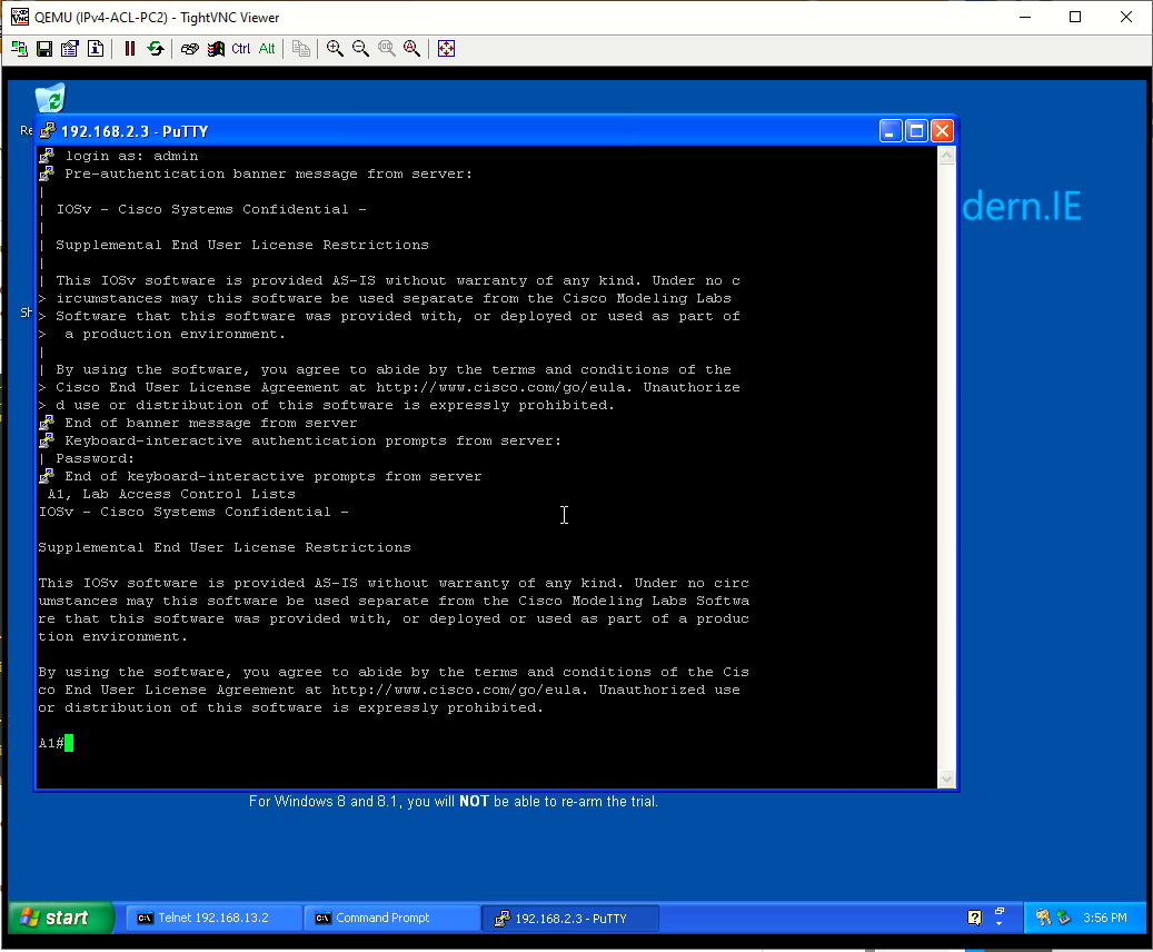
Step 1: Test Telnet connectivity
From both PCs test Telnet connectivity to all devices. You should be successful. Troubleshoot as needed.
|
|
|
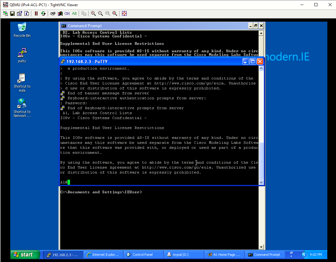
Step 2: Test SSH connectivity.
From both PCs test SSH to A1. You should be successful. Troubleshoot as needed.
|
|
|
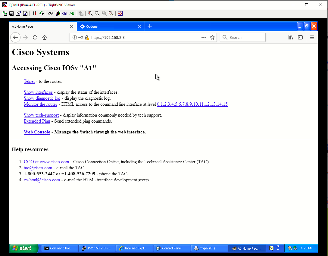
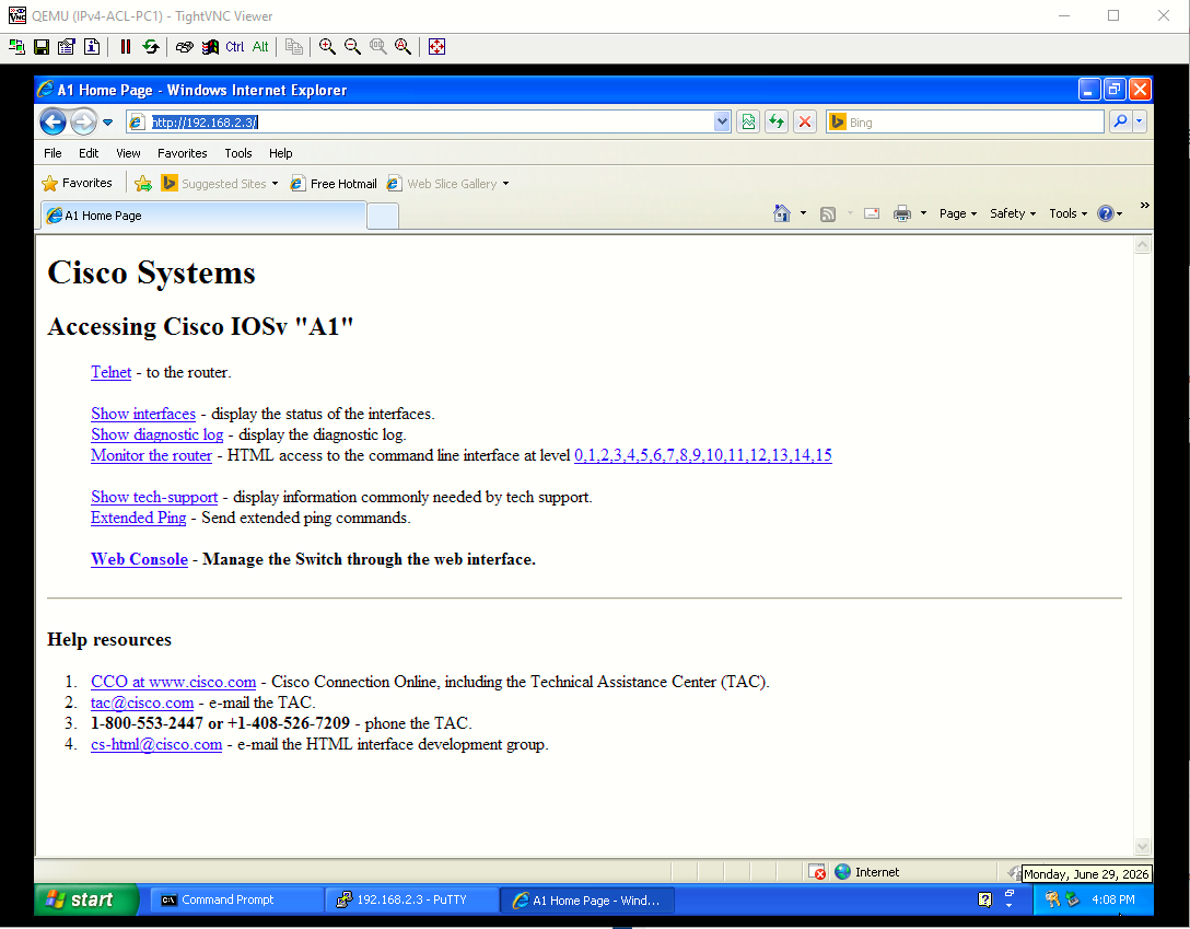
Step 3: Test HTTP and HTTPS connectivity
- From PC1, open a web browser and HTTP to A1. You will be prompted for a username/password. You should be successful. Troubleshoot as needed.

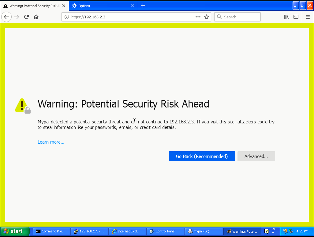
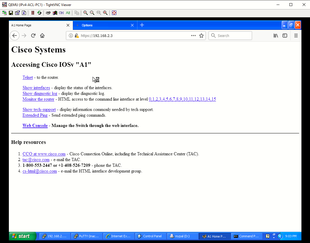
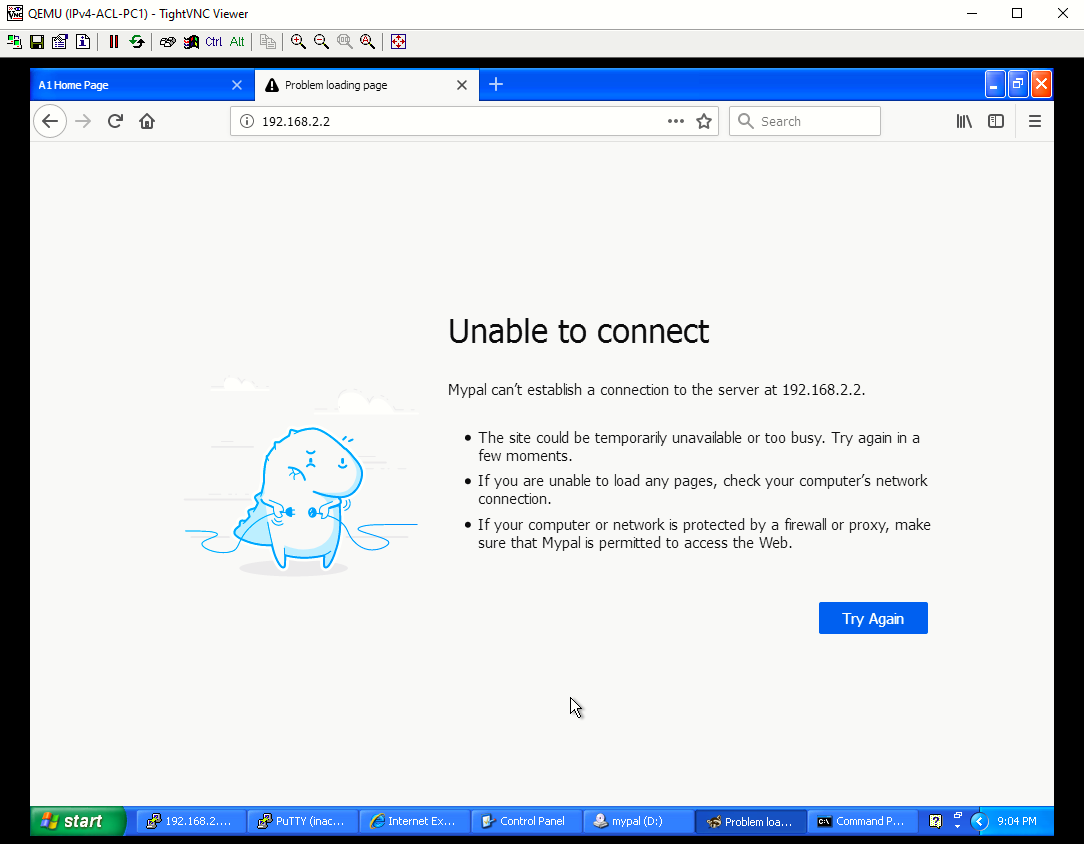
- From PC1, open a web browser and access A1 via HTTPS. A warning will appear in the web browser when connecting via HTTPS because A1 generated a self-signed certificate. Continue to access A1 via HTTPS. You should be successful. Troubleshoot as needed.
Note: Ignoring a web browser warning on the internet could expose your computer to risk. But it is safe to do so in a lab environment where the equipment has no access to production networks or the internet.
Note: If you received the error, SSL_ERROR_INTERNAL_ERROR_ALERT, while trying to connect to A1 via the web browser, enter the following command to create a new self-signed certificate for secure communications.
no ip http server
no ip http secure-server
no ip http authentication local
ip http server
ip http secure-server
ip http authentication local

Part 3: Implement Standard ACLs on R3
A standard ACL matches traffic by source IP and is typically placed close to the destination. It can be named or numbered, with ranges 1-99 and 1300-1999.
Step 1: Configure a numbered standard ACL on R3 and block data traffic from the 192.168.1.0/24 network. Create a numbered standard ACL using the number 99 to deny the source network of 192.168.1.0/24. Then add a second ACE to permit all other traffic.

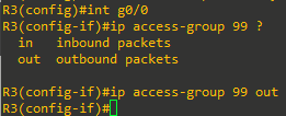
Step 2: Apply the numbered standard ACL to the correct interface and in the correct direction. Apply the ACL to the G0/0 on R3. Specify outbound G0/0 because the data traffic is originating from R1 and exiting G0/0 to access the 192.168.2.0/24 network.
Step 3: Verify that the numbered standard ACL is working properly
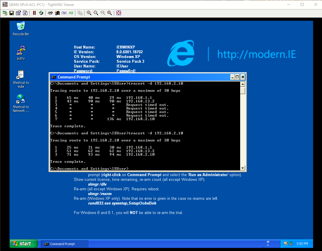
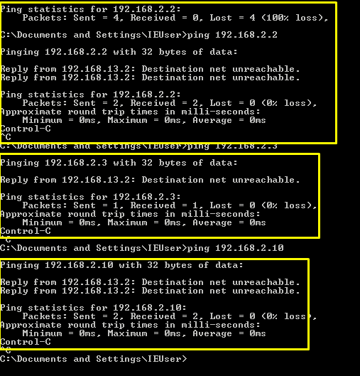
- From PC1, ping D2, A1, and PC2. The pings should fail. Notice the messages on PC1 is from R3.
- Issue the show access-lists command on R3. The output shows packets matching the sequence number 10.

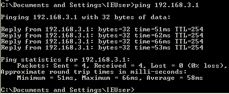
- Next, from PC1, ping the loopback on R3 at 192.168.3.1. The ping should be successful. This verifies connectivity to resources on R3. However, ACL 99 denies access to the 192.168.2.0/24 network.
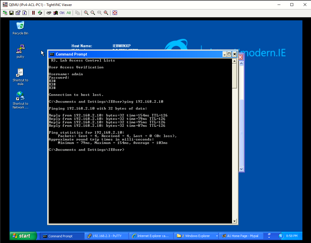
- Remove the access list from R3 and remove the ip access-group command from interface G0/0 to provide connectivity to 192.168.2.0/24 network.
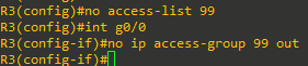
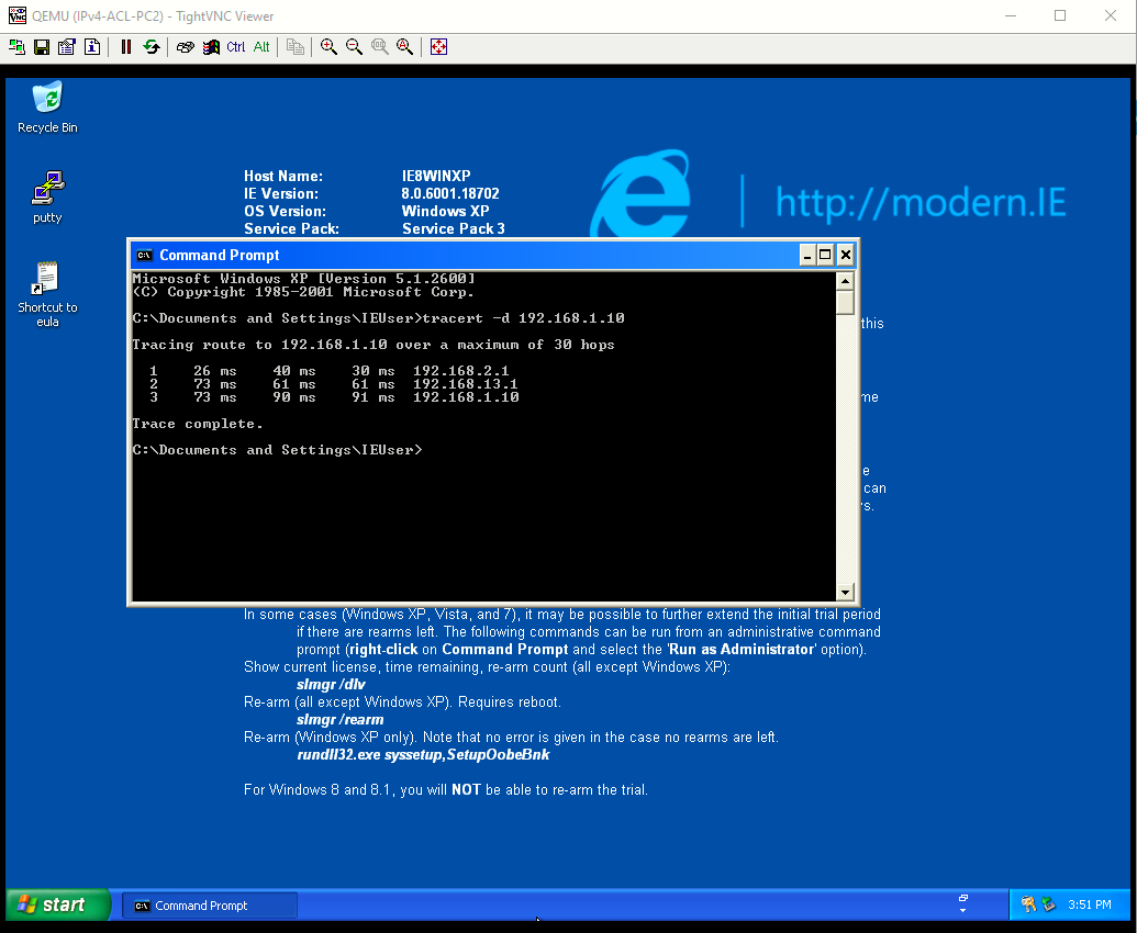
- Verify that PC1 can ping devices on the 192.168.2.0/24 network.


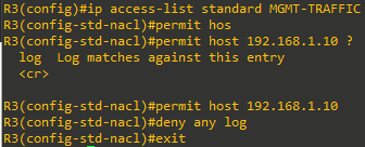
Step 4: Configure a named standard ACL to limit management traffic to R3. Create a named standard ACL using the name MGMT-TRAFFIC. The ACL should only permit Telnet access to the management plane on R3 from PC1. Explicitly deny access from any other IPv4 destination and log the attempts
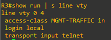
Step 5: Apply the named standard ACL to the correct interface and in the correct direction. Use the access-class command to apply the MGMT-TRAFFIC ACL to all inbound vty lines on R3. Outbound Telnet connections from R3 will still be allowed.
Step 6: Verify that the named standard ACL is working properly.
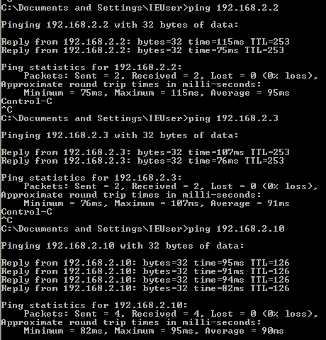
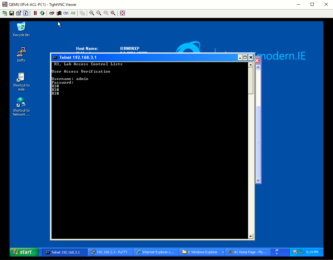
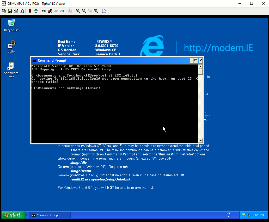
- Test the ACL by initiating a Telnet session from PC1 to the Loopback address (192.168.3.1) on R3. The results should be successful. Repeat the test from PC2. Telnet connectivity from PC2 should be denied.


- On R3, you should see the console messages shown below. The first message shows a login success and the second message shows a denial.

- Issue the show access-lists on R3 to view the packet “matches” from each ACE.
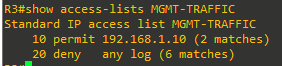
Note: During testing, the first packet in a flow will trigger a syslog message. Enabling logging with the log option in the deny any statement provides insight into the amount of denied traffic. Unfortunately, ACL logging can be CPU-intensive and can negatively affect other functions of the network device. There are two primary factors that contribute to the CPU load increase from ACL logging: process switching of packets that match log-enabled access control entries (ACEs), and the generation and transmission of log messages. Care should be taken when using the log option in a production network.


Part 4: Implement a Named Extended ACL from Area 1 to Area 2
Extended ACLs can filter traffic based on more than just source address. Extended ACLs can filter on protocol, source, and destination IP addresses, and source and destination port numbers. Extended ACLs may also be used to filter IP packets with header options.
When filtering data traffic using an extended ACL, it is considered best practice to apply the ACL as close to the source as possible. You can configure both numbered and named extended ACLs. Part 4 of this lab uses a named extended ACL. Review the ACL policy that will be implemented using a named extended ACL.
On R1, use the following requirements to create a named extended ACL that will filter traffic originating from OSPF area 1 destined to OSPF area 2. As a result, all traffic from area 2 destined to area 1 will also be filtered:
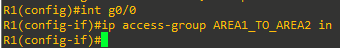
- Name the extended ACL AREA1_TO_AREA2.
- Deny any IP traffic from PC1 with a time-to-live (TTL) value less than 25.
- Permit PC1 to send ICMP echo packets to 192.168.2.0/24.
- Permit PC1 Telnet access to D2.
- Permit 192.168.1.0/24 network to SSH to A1.
- Permit PC1 to send HTTP traffic to A1.
- Permit PC1 to send HTTPS traffic to A1.
- Explicitly deny all other traffic.
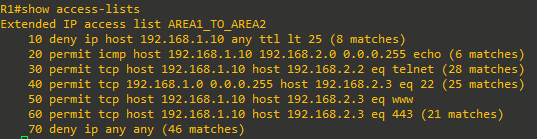
Step 1: Configure the named extended ACL on R1. Then, issue the show access-list command to verify the creation of the extended named ACL. Notice the sequence numbers and the top (lower sequence number) to bottom (higher sequence number) processing of each ACE. Also notice some of the port numbers have been changed to the IOS keywords. For example, port 80 is now www in the IOS.
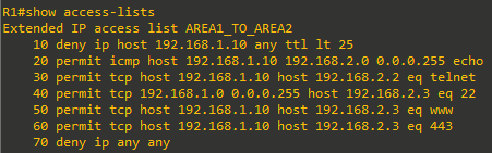
Note: Sequence 70 essentially filters all other traffic that does not originate from area 1.
Step 2: Apply the named extended ACL to the correct interface and in the correct direction. Apply the named ACL to the G0/0 interface on R1. Because traffic originates from area 1, apply the ACL inbound to R1
Step 3: Verify that the AREA1_TO_AREA2 named extended ACL is working properly.
- Test the first two lines of the ACL. From PC1, you should be able to successfully ping PC2.
- From PC1, ping PC2 again, but this time set the TTL value to 20 inside the IP header on PC1. Use the following command on PC1 to set the TTL to 20 for the ICMP packet.
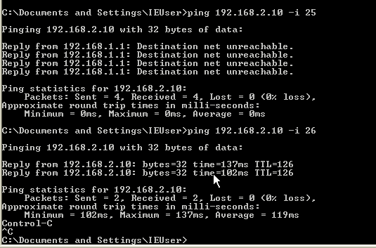
The ICMP packets with a TTL value of 20 should be dropped by R1, which is the area border router
(ABR) for area 1. R1 sends error messages to PC1. - Continue to test each individual ACE within the ACL.
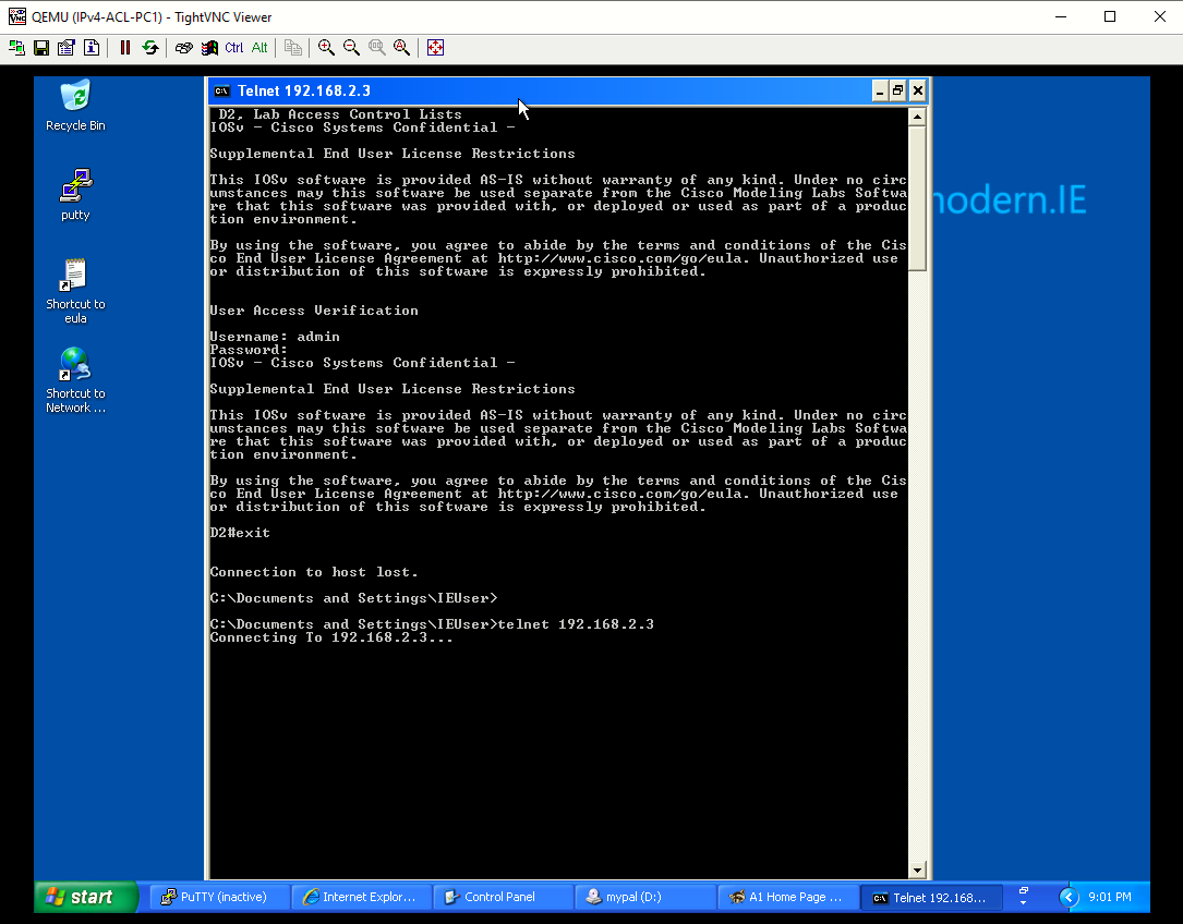
- From PC1, you should be able to successfully access D2 via Telnet. However, accessing any other
device in area 2 via Telnet should be denied.

- From any device in area 1, you should be able to SSH to A1. However, accessing any other device
on area 2 via SSH should be denied.
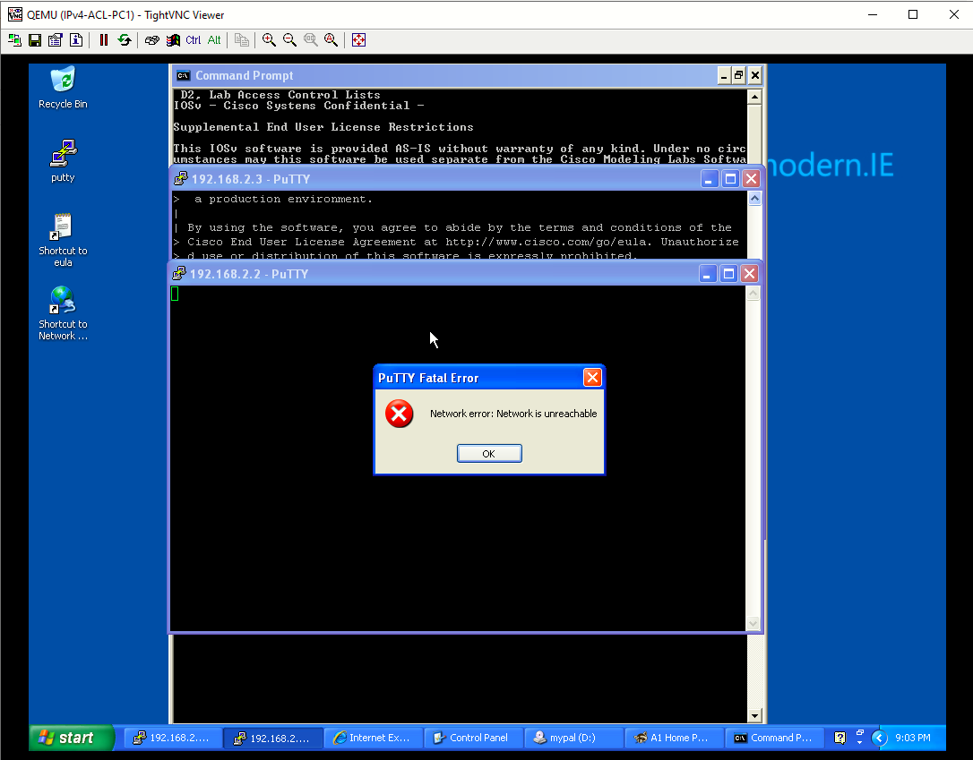
- From PC1, you should be able to access the web interface on A1 using either HTTP or HTTPS.
However, all other attempts to access other devices using HTTP and HTTPS should time out.


- From PC1, you should be able to successfully access D2 via Telnet. However, accessing any other
- After testing each ACE, issue the show access-list command. Notice that each ACE has matches. Your match counts will be different.


Part 5: Implement a Named Extended ACL from Area 1 to Area 2
In this Part, you will configure and verify a named extended ACL to permit specific returning traffic from area 2. To do this, you will now configure the addressing and port numbers from area 2 as the source addresses and source ports. Additionally, the established keyword will be set on returning TCP connections to increase security.
Step 1: Configure the named extended ACL on R1.
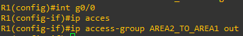
- Use this filtered output from the show run command below to configure the named extended ACL AREA2_TO_AREA1 on R1.
R1(config)#ip access-list extended AREA2_TO_AREA1 R1(config-ext-nacl)#$ 192.168.2.0 0.0.0.255 host 192.168.1.10 echo-reply R1(config-ext-nacl)#$host 192.168.2.2 eq telnet host 192.168.1.10 established R1(config-ext-nacl)#$host 192.168.2.3 eq 22 192.168.1.0 0.0.0.255 established R1(config-ext-nacl)#$host 192.168.2.3 eq www host 192.168.1.10 established R1(config-ext-nacl)#$host 192.168.2.3 eq 443 host 192.168.1.10 established R1(config-ext-nacl)#deny ip any any log - Next, apply the ACL to the G0/0 interface in the outgoing direction. Because traffic originated from area 1 and is returning from area 2, configure the ACL going outbound on the G0/0 interface towards area 1.

Step 2: Verify that the AREA2_TO_AREA1 named extended ACL is working properly.
- Repeat the tests from Part 4, Step 4. The return traffic permitted in the ACL AREA2_TO_AREA1 should be successful.
All tests successful - Issue the show ip access-list AREA2_TO_AREA1 command on R1 to see the matches for the return traffic from area 2.
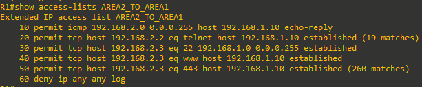
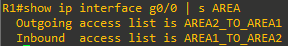
Note: The established option allows only TCP responses to traffic that originates from area 1 (192.168.1.0/24) to return. A match occurs if the returning TCP segment has either the ACK or reset (RST) bit set. Either of these bits indicates that the packet belongs to an established connection. Therefore, when filtering return traffic, the source port number must be checked. - To verify that both ACLs are applied to the G0/0/1 interface on R1, issue the following filtered show ip interface command.


Part 6: Implement a Port ACL on D2
Port ACLs (PACLs) are like the router ACLs (RACLs) configured previously in this lab. However, PACLs are supported on Layer 2 switchports. PACLs can be implemented using standard or extended ACLs but can only be applied inbound. The processing of a PACL is done before a VLAN ACL (VACL) and RACL.
Step 1: Configure a PACL on D2 using the following requirements_
On D2, create an extended numbered PACL on port 23 which has the following requirements:
- Deny all ICMP messages sent to 192.168.2.3
- Deny Telnet access to 192.168.2.2
- Permit all other traffic
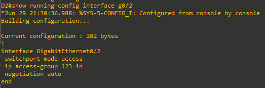
Step 2: Apply the PACL to an interface on D2
On D2, apply the ACL inbound on G0/2
Step 3: Verify that the PACL is working properly
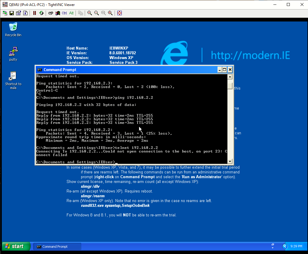
From PC2 test each ACE within the PACL.
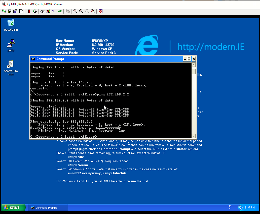
- A ping from PC2 to A1 should not be successful. However, a ping from PC2 to D2 should be successful.

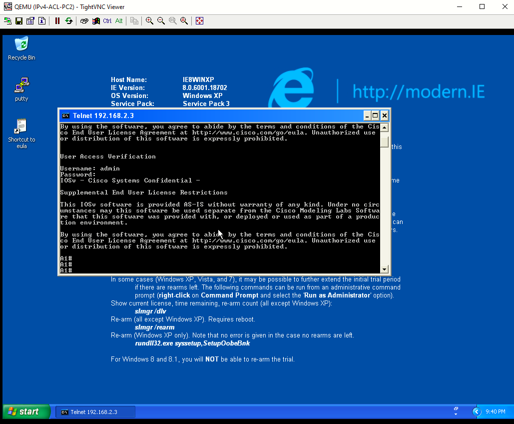
- Access via Telnet from PC2 to D2 should fail. However, access via Telnet and SSH from PC2 to A1 should be successful.

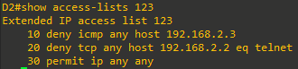
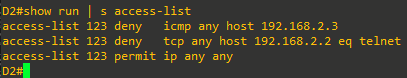
- On D2 issue the show run | s access-list command. Notice the numbered ACL 123 configured earlier is now converted into the format for an extended named ACL.


Part 7: Implement a VLAN ACL on D2
VLAN ACLs (VACLs) control access to the VLAN of all packets, both bridged and routed. Packets can enter the VLAN via a Layer 2 switchport or through a Layer 3 interface after being routed. Like PACLs, VACLs can filter traffic within the same VLAN.
Step 1: Configure a VACL on D2 using the following requirements:
Create an extended VACL to support the following requirements:
- Deny pings from 192.168.2.2 to 192.168.2.3.
- Deny Telnet from 192.168.2.2 to 192.168.2.3.
- Permit all other traffic.
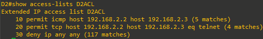
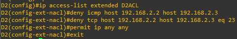
- On D2 create an extended ACL named D2ACL. Notice that in this first configuration step, the traffic to be blocked is defined in the ACL with a permit statement. That is because in Step1c, you will configure a vlan access-map to match this permitted traffic and then drop it. All denied traffic will not match the first vlan access-map statement, but will match the second vlan access-map statement in Step1d. This second statement will forward all other traffic.
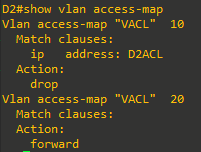
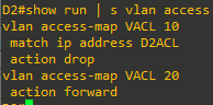
- On D2, configure the VLAN access map with the name VACL and sequence 10. Within the VLAN access map match the access list named D2ACL. Then set the action to drop any packets being permitted by the D2ACL. Like all ACLs, there is an implied “deny any” with a VLAN ACL. To prevent all traffic from being dropped, create a sequence 20 for the same VLAN access map. Next, set the action to forward.


Step 2: Apply the VACL to a VLAN filter.
To apply a VACL, use the vlan filter vlan-access-map-name vlan-list vlan-list command. The vlan-list can be a single VLAN, a contiguous range of VLANs (7-10), or a comma separated list of multiple VLANs (4,9-11,17). Notice a direction is not required because the VLAN filter applies to both intra-VLAN in inter-VLAN traffic.

Step 3: Apply the VACL to a VLAN filter.
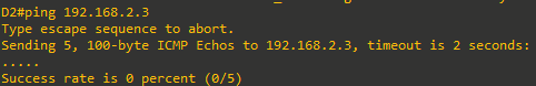
From D2, test each ACE within the VACL.
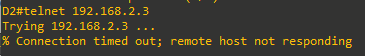
- From D2, ping A1. The ping should fail.

- From D2, use Telnet to access A1. The connection should time out
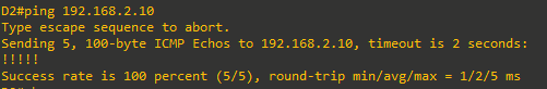
- From D2, ping PC2. The ping should be successful.
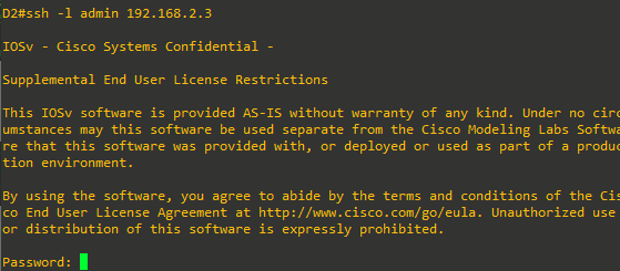
- From D2, SSH to A1. The connection should be successful. Exit the SSH session.
- Use the show vlan access-map and show access-list commands to view the VACL configuration.