
Lab - Implement HSRP
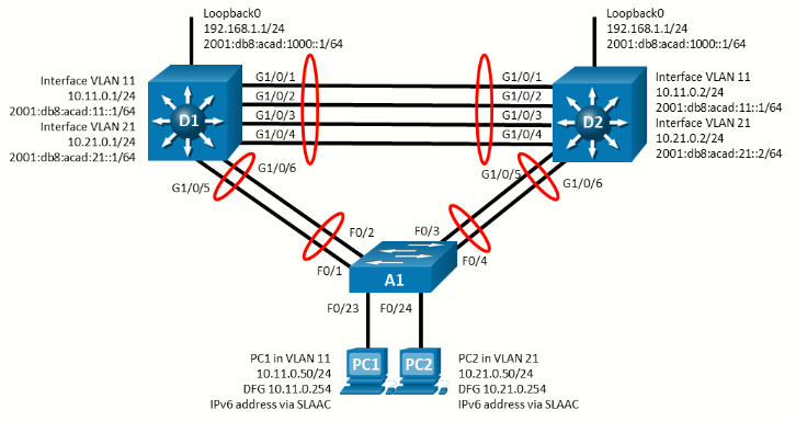
Topology
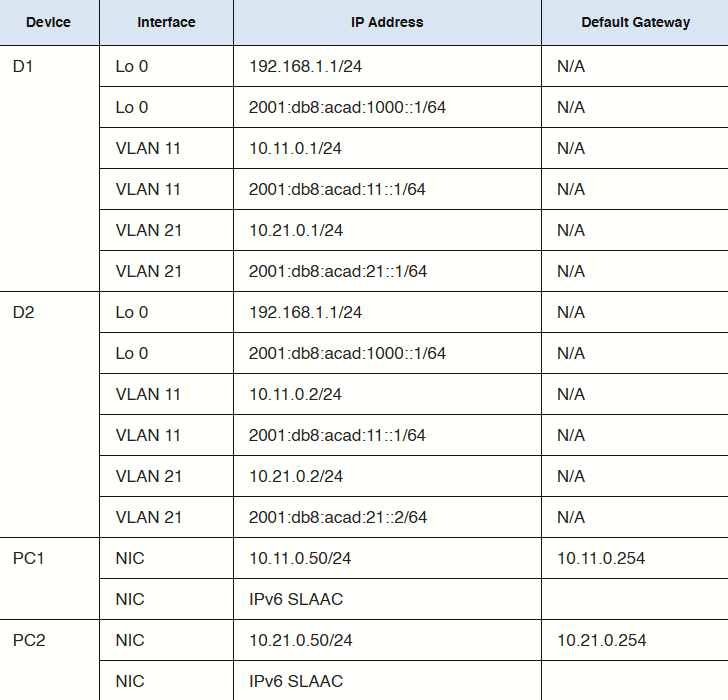
Addressing Table
Objectives
- Part 1: Build the Network and Configure Basic Device Settings and Interface Addressing
- Part 2: Configure and Observe HSRP for IPv4 and IPv6
- Part 3: Configure and Observe HSRP Authentication
- Part 4: Configure and Observe HSRP Object Tracking
Background / Scenario
Hot Standby Router Protocol (HSRP) is a Cisco-proprietary redundancy protocol for establishing a fault-tolerant default gateway. It is described in RFC 2281. HSRP provides a transparent failover mechanism to the end stations on the network. This provides users at the access layer with uninterrupted service to the network if the primary gateway becomes inaccessible.
Note: This lab is an exercise in deploying and verifying HSRP and does not necessarily reflect networking best practices.
Note: The switches used with CCNP hands-on labs are Cisco 3650 with Cisco IOS XE release 16.9.4 (universalk9 image) and Cisco 2960 with IOS release 15.2 (lanbase image). Other routers and Cisco IOS versions can be used. Depending on the model and Cisco IOS version, the commands available and the output produced might vary from what is shown in the labs.
Note: Ensure that the switches have been erased and have no startup configurations. If using 3560s configure:
sdm prefer dual-ipv4-and-ipv6 routingRequired Resources - Sergio Jimenez's Version
- 2 Switches (Cisco 3550)
- 1 Switch (Cisco 2960CX)
- 2 PC (Choice of operating system with a terminal emulation program installed)
- Console cables to configure the Cisco IOS devices via the console ports
- Ethernet cables as shown in the topology
Instructions
Part 1: Build the Network and Configure Basic Device Settings and Interface Addressing
In Part 1, you will set up the network topology and configure basic settings and interface addressing.
Step 1: Cable the network as shown in the topology
Attach the devices as shown in the topology diagram, and cable as necessary.
Step 2: Configure basic settings for each switch.
Switch D1
hostname D1
ip routing
ipv6 unicast-routing
no ip domain lookup
banner motd # D1, Implement HSRP #
line con 0
 exec-timeout 0 0
 logging synchronous
 exit
line vty 0 4
 privilege level 15
 password cisco123
 exec-timeout 0 0
 logging synchronous
 login
 exit
interface range f0/1-6
 switchport trunk encapsulation dot1q
 switchport mode trunk
 no shutdown
 exit
interface range f0/1-4
 channel-group 12 mode active
 exit
interface range f0/5-6
 channel-group 1 mode active
 exit
vlan 11
 name FIRST_VLAN
 exit
vlan 21
 name SECOND_VLAN
 exit
interface vlan 11
 ip address 10.11.0.1 255.255.255.0
 ipv6 address fe80::d1:1 link-local
 ipv6 address 2001:db8:acad:11::1/64
 no shutdown
 exit
interface vlan 21
 ip address 10.21.0.1 255.255.255.0
 ipv6 address fe80::d1:2 link-local
 ipv6 address 2001:db8:acad:21::1/64
 no shutdown
 exit
interface loopback 0
 ip address 192.168.1.1 255.255.255.0
 ipv6 address fe80::d1:3 link-local
 ipv6 address 2001:db8:acad:1000::1/64
 no shutdown
 exit
Switch D2
hostname D2
ip routing
ipv6 unicast-routing
no ip domain lookup
banner motd # D2, Implement HSRP #
line con 0
exec-timeout 0 0
logging synchronous
exit
line vty 0 4
privilege level 15
password cisco123
exec-timeout 0 0
logging synchronous
login
exit
interface range f0/1-6
switchport trunk encapsulation dot1q
switchport mode trunk
no shutdown
exit
interface range f0/1-4
channel-group 12 mode active
exit
interface range f0/5-6
channel-group 2 mode active
exit
vlan 11
name FIRST_VLAN
exit
vlan 21
name SECOND_VLAN
exit
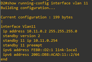
interface vlan 11
ip address 10.11.0.2 255.255.255.0
ipv6 address fe80::d2:1 link-local
ipv6 address 2001:db8:acad:11::2/64
no shutdown
exit
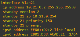
interface vlan 21
ip address 10.21.0.2 255.255.255.0
ipv6 address fe80::d2:2 link-local
ipv6 address 2001:db8:acad:21::2/64
no shutdown
exit
interface loopback 0
ip address 192.168.1.1 255.255.255.0
ipv6 address fe80::d2:3 link-local
ipv6 address 2001:db8:acad:1000::1/64
no shutdown
exitSwitch A1
hostname A1
banner motd # A1, Implement HSRP #
line con 0
 exec-timeout 0 0
 logging synchronous
 exit
line vty 0 4
 privilege level 15
 password cisco123
 exec-timeout 0 0
 logging synchronous
 login
 exit
interface range g0/1-4
 switchport mode trunk
 no shutdown
 exit
interface range g0/1-2
 channel-group 1 mode active
 exit
interface range g0/3-4
 channel-group 2 mode active
 exit
vlan 11
 name FIRST_VLAN
 exit
vlan 21
 name SECOND_VLAN
 exit
interface g0/9
 switchport mode access
 switchport access vlan 11
 spanning-tree portfast
 no shutdown
 exit
interface g0/10
 switchport mode access
 switchport access vlan 21
 spanning-tree portfast
 no shutdown
 exit
interface vlan 11
 ip address 10.11.0.3 255.255.255.0
 ipv6 address fe80::a1:1 link-local
 ipv6 address 2001:db8:acad:11::3/64
 no shutdown
 exit
ip default-gateway 10.11.0.254
Step 3: Configure the PCs for network connectivity
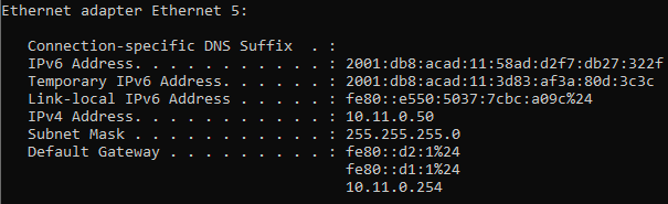
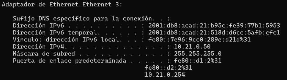
Configure PC1 and PC2 with the IPv4 address, subnet mask, and default gateway specified in the topology diagram. The IPv6 address and default gateway information for each PC will come from SLAAC.
|
|
|
Part 2: Configure and Observe HSRP for IPv4
On the 3560 IPv4 and IPv6 are mutually exclusive. Only one IP version per interface. Hence its not possible to lab both protocols at the same time. I'll finally do only IPv4.
In Part 2, you will configure and test HSRPv2 in support of IPv4
HSRP provides redundancy in the network. The traffic can be load-balanced by using the standby group priority priority command.
IP routing is enabled on D1 and D2. Each route processor can route between the SVIs configured on its switch. In addition to the real IP address assigned to each switch SVI, assign a third IP address in each subnet to be used as a virtual gateway address. HSRP negotiates and determines which switch accepts information forwarded to the virtual gateway IP address.
The standby command configures the IP address of the virtual gateway, sets the priority for each group, and configures the router for preemption. Preemption allows the router with the higher priority to become the active router after a network failure has been resolved. Notice that the abbreviation HSRP is not used in the command syntax to implement HSRP. HSRP version 2 must be implemented to support IPv6. This is accomplished by using the standby version 2 command on every interface required.
The standby x ipv6 autoconfig command, where x is the assigned HSRP group number, is used to assign the group an automatically generated virtual ipv6 address. Note that the group number used for IPv6 on an interface must be different than the group used for IPv4.
In this lab, the group numbers will be 11 and 21 for IPv4, and 116 and 216 for IPv6.
In the following configurations, the priority for VLAN 11 on D1 is set to 150, making it the active router for VLAN 11. VLAN 21 has the default priority of 100 on D1, making D1 the standby router for VLAN 21. D2 is configured to be the active router for VLAN 21 with a priority of 150, and the standby router for VLAN 11 with a default priority of 100.
Note: It is recommended that the HSRP group number be mapped to VLAN number.
Step 1: Configure HSRPv2 on Switch D1
-
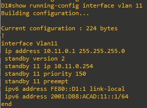
Configure standby group 11 on interface VLAN 11 for HSRP version 2, a standby IP address of 10.11.0.254, a priority of 150, and preemption.

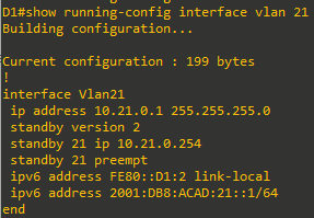
- Configure standby group 21 on interface VLAN 21 for HSRP version 2, a standby IP address of 10.21.0.254, and preemption.

Step 2: Verify HSRPv2 is operational on Switch D1
-
Verify that HSRP is active and operating on Switch D1 with the
show standby briefcommand.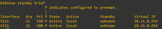
-
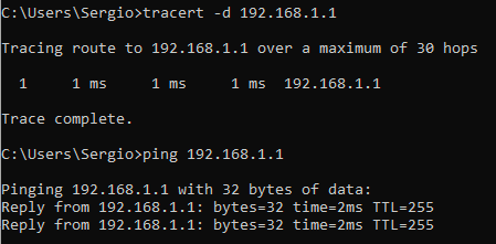
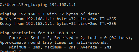
Interface Loopback0 on D1 and D2 represent a destination on the internet. From PC1 and PC2, ping the IPv4 of interface Loopack0 on D1. A successful ping verifies that the gateway router is working.


Step 3: Configure HSRPv2 on Switch D2
-
Configure standby group 11 on interface VLAN 11 for HSRP version 2, a standby IP address of 10.11.0.254, and preemption.
- Configure standby group 21 on interface VLAN 21 for HSRP version 2, a standby IP address of 10.21.0.254, a priority of 150, and preemption.


Step 4: Verify HSRPv2 is operational on Switch D2
-
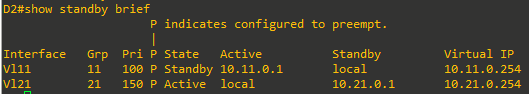
Verify that HSRP is active and operating on Switch D2 with the
show standby briefcommand. Based on the configuration, D2 should be the active switch for VLAN 21 only.
-
Interface Loopback0 on D1 and D2 represent a destination on the internet. From PC1 and PC2, ping the IPv4 and IPv6 address of interface Loopack0 on D1. A successful ping verifies that the gateway router is working.

Step 5: Observe and validate HSRPv2 operation
The whole point of HSRP is to help maintain gateway reachability in case of an outage. In this step, we will simulate an outage to show how HSRP achieves this objective.
- On PC1, start a continuous ping to 192.168.1.1
- On Switch D1, issue the
shutdowncommand on interface VLAN 11. Note that D2 takes over the active role, and there is very little traffic loss in the running pings.
- On Switch D1, issue the
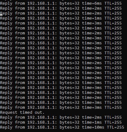
no shutdowncommand on interface VLAN 11. Note that D1 takes back over as the active router, and once again there is very little traffic loss experienced. - Stop the continuous ping running on PC1.

Step 6: Tune HSRPv2 operation
We have validated the operation of HSRP for both IPv4, and our gateways are now redundant. But in some cases, the default amount of time taken to detect and react to an outage is too slow. By default, HSRP uses a 3-second hello timer and a 10-second hold timer. If 10 seconds is too slow for your organization or traffic scenario, you can tune the HSRP timers to speed things up. This should only be done on a stable network, and this will cause more HSRP traffic to be sent between the configured switches, so you should take those factors into account before changing the timers on a production network.
-
On both switches, issue the
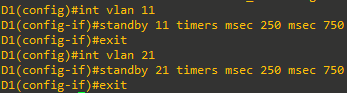
shutdowncommand on interface VLAN 11 and VLAN 21. -
On both switches, configure the timers for standby group 11 and standby group 21 so that the hello time is 250 milliseconds and the hold time is 750 milliseconds.
-
On both switches, issue the
no shutdowncommand on interface VLAN 11 and VLAN 21 and let HSRP initialize. Verify that it is operating as designed by issuing theshow standby briefcommand on switch D1. You should see D1 as active for VLAN 11 and standby for VLAN 21.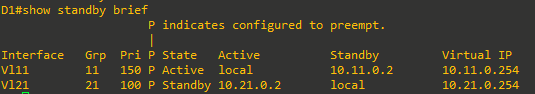
-
On PC1, start a continuous ping to 192.168.1.1
-
On Switch D1, issue the
shutdowncommand on interface VLAN 11. Note that that D2 takes over the active role almost immediately, and there is almost no traffic loss in the running pings.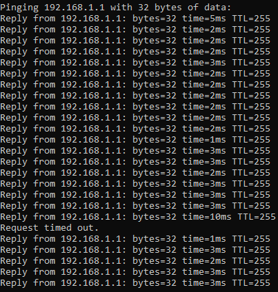
-
On Switch D1, issue the
no shutdowncommand on interface VLAN 11. Note that D1 takes back over as the active router, and once again there is almost no traffic loss experienced. -
Stop the continuous ping running on PC1.


Part 3: Configure and Observe HSRP Authentication
In this part of the lab, you will secure the HSRP communication between member devices. HSRP authentication prevents rogue routers on the network from joining the HSRP group. Without authentication, a rogue router could join the group and claim the active role. The attacker would then be able to capture all the traffic forwarded to attacker’s device. HSRP authentication can be configured using plaintext, an MD5-hashed key-string, or an MD5-hashed key chain. Using key chains offers more options and security because you can have lifetime parameters associated with the different keys. For simplicity, we will configure HSRP authentication using the key string option.
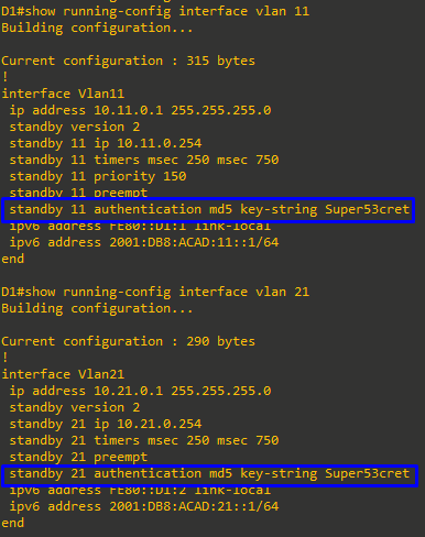
- On D1, configure authentication for group 11 and group 21 using the key-string
Super53cret.
-
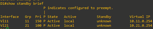
Notice as soon as this command was entered on D1 that we received a “bad authentication” message display to the console screen. HSRP authentication is not yet configured on D2 therefore we expect for the HSRP process to be disrupted. The output of the
show standby briefcommand below confirms that D2 is no longer the standby router for group 11. The standby router shows unknown.

-
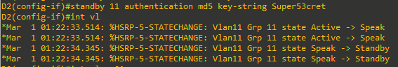
On D2, configure authentication for group 11 and group 21 using the key-string Super53cret.
-
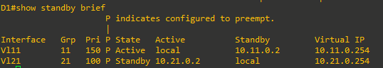
As soon as the key string was entered, HSRP started working again. Verify this by examining the output of
show standby briefon D1 and you will see that D2 is now listed as the standby router for group 11.


Part 4: Configure and Observe HSRP Object Tracking
HSRP can perform object and interface tracking. Either of these tracking methods enables the priority of a standby group router to be automatically adjusted, based on the status of the tracked entity. When a tracked entity becomes unavailable, the HSRP priority of the router is decreased. With preemption configured on the HSRP group, this might cause another router to take over as the active router for a group based on its higher priority value. When properly configured, the HSRP tracking feature ensures that a router with an unavailable key interface will relinquish the active router role.
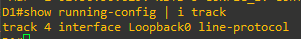
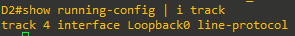
Step 1: Create a tracked object
Create an object on Switch D1 and D2 that tracks the line-protocol of interface Loopback 0.
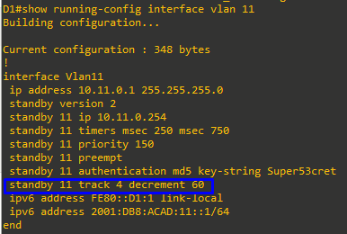
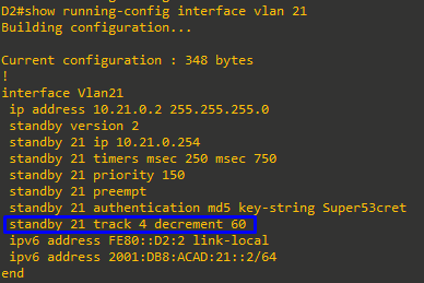
Step 2: Configure HSRP to track the object status
On D1, configure standby groups 11 and 116 to track the status of track 4. On D2, configure standby groups 21 and 216 to track the status of track 4. When the tracked object has failed, decrement the system priority by 60.
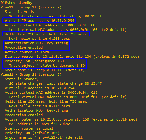
Step 3: Verify the HSRP configuration.
Issue the command show standby on Switch D1. This is the full version of the command, and in the output, you can see all the adjustments that have been made to this point.
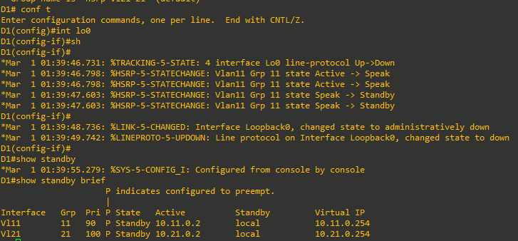
Step 4: Verify HSRP complies with the configuration.
-
On D1, shut down interface Loopback 1. Switch D2 should take over as active for group 11. Verify D1’s current priority value and D2’s status with the
show standby briefcommand.
-
Examine the priority information in detail in the output of the
show standbycommand.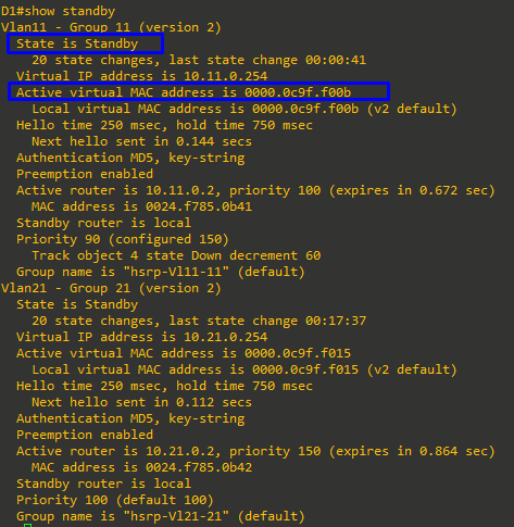

Device Configs - Final
Switch D1 (3560)
D1#sh run
Building configuration...

Current configuration : 4194 bytes
!
! Last configuration change at 01:39:55 UTC Mon Mar 1 1993
!
version 15.0
no service pad
service timestamps debug datetime msec
service timestamps log datetime msec
no service password-encryption
!
hostname D1
!
boot-start-marker
boot-end-marker
!
!
!
no aaa new-model
system mtu routing 1500
ip routing
no ip domain-lookup
!
!
!
ipv6 unicast-routing
!
!
crypto pki trustpoint TP-self-signed-1832650624
 enrollment selfsigned
 subject-name cn=IOS-Self-Signed-Certificate-1832650624
 revocation-check none
 rsakeypair TP-self-signed-1832650624
!
!
crypto pki certificate chain TP-self-signed-1832650624
 certificate self-signed 01
  3082022B 30820194 A0030201 02020101 300D0609 2A864886 F70D0101 05050030
  31312F30 2D060355 04031326 494F532D 53656C66 2D536967 6E65642D 43657274
  69666963 6174652D 31383332 36353036 3234301E 170D3933 30333031 30303031
  30375A17 0D323030 31303130 30303030 305A3031 312F302D 06035504 03132649
  4F532D53 656C662D 5369676E 65642D43 65727469 66696361 74652D31 38333236
  35303632 3430819F 300D0609 2A864886 F70D0101 01050003 818D0030 81890281
  81009A76 211880E6 22D63FA4 6C349AB0 BB71B791 6F13BD6D 965A380F 08090FE8
  435743F5 D9AB6DE4 C7A2CFC6 FC701398 513552E2 EB67980E D7A2926C 784CC290
  7DB7DE3E E67C33BE 8C60CD6A 95BCFF0F 0428114A 119C0F07 0D5E2DC7 E534752F
  75C3E15D 16FD8067 AB1F7F12 657DE81A 05FE50D3 24F16A3F F0882E60 6FB5BBA4
  FFF50203 010001A3 53305130 0F060355 1D130101 FF040530 030101FF 301F0603
  551D2304 18301680 14096EA9 129C70BB 04324DB8 F9E6B6A2 E5C43162 72301D06
  03551D0E 04160414 096EA912 9C70BB04 324DB8F9 E6B6A2E5 C4316272 300D0609
  2A864886 F70D0101 05050003 81810078 492F714A F1E52D83 C6696DD0 CD3DA01A
  5A6B69E0 349B46E3 FC25A9D6 843765A1 287D7B7C C954853D 34CC0258 89F014A6
  D07ED964 66111CD1 4967219D 2F25D4C0 2EE1ADF5 FA89CBF9 DDDD4024 D982126E
  746D5A23 9EE1FB7E 39957C57 5508AD2F 094127F6 3CF778B9 FF18FA5F 5D17DD39
  205EF3E6 87163600 58C21104 DE41CB
        quit
!
!
!
!
!
spanning-tree mode pvst
spanning-tree extend system-id
!
vlan internal allocation policy ascending
!
track 4 interface Loopback0 line-protocol
!
!
!
!
!
!
!
!
!
!
!
!
!
!
!
interface Loopback0
 ip address 192.168.1.1 255.255.255.0
 shutdown
 ipv6 address FE80::D1:3 link-local
 ipv6 address 2001:DB8:ACAD:1000::1/64
!
interface Port-channel1
 switchport trunk encapsulation dot1q
 switchport mode trunk
!
interface Port-channel12
 switchport trunk encapsulation dot1q
 switchport mode trunk
!
interface FastEthernet0/1
 switchport trunk encapsulation dot1q
 switchport mode trunk
 channel-group 12 mode active
!
interface FastEthernet0/2
 switchport trunk encapsulation dot1q
 switchport mode trunk
 channel-group 12 mode active
!
interface FastEthernet0/3
 switchport trunk encapsulation dot1q
 switchport mode trunk
 channel-group 12 mode active
!
interface FastEthernet0/4
 switchport trunk encapsulation dot1q
 switchport mode trunk
 channel-group 12 mode active
!
interface FastEthernet0/5
 switchport trunk encapsulation dot1q
 switchport mode trunk
 channel-group 1 mode active
!
interface FastEthernet0/6
 switchport trunk encapsulation dot1q
 switchport mode trunk
 channel-group 1 mode active
!
interface FastEthernet0/7
!
interface FastEthernet0/8
!
interface GigabitEthernet0/1
!
interface Vlan1
 no ip address
 shutdown
!
interface Vlan11
 ip address 10.11.0.1 255.255.255.0
 standby version 2
 standby 11 ip 10.11.0.254
 standby 11 timers msec 250 msec 750
 standby 11 priority 150
 standby 11 preempt
 standby 11 authentication md5 key-string Super53cret
 standby 11 track 4 decrement 60
 ipv6 address FE80::D1:1 link-local
 ipv6 address 2001:DB8:ACAD:11::1/64
!
interface Vlan21
 ip address 10.21.0.1 255.255.255.0
 standby version 2
 standby 21 ip 10.21.0.254
 standby 21 timers msec 250 msec 750
 standby 21 preempt
 standby 21 authentication md5 key-string Super53cret
 ipv6 address FE80::D1:2 link-local
 ipv6 address 2001:DB8:ACAD:21::1/64
!
ip http server
ip http secure-server
!
!
!
!
!
!
vstack
banner motd ^C D1, Implement HSRP ^C
!
line con 0
 exec-timeout 0 0
 logging synchronous
line vty 0 4
 exec-timeout 0 0
 privilege level 15
 password cisco123
 logging synchronous
 login
line vty 5 15
 login
!
end

D1#
Switch D2 (3560)
D2#sh run
Building configuration...

Current configuration : 4184 bytes
!
! Last configuration change at 01:38:01 UTC Mon Mar 1 1993
!
version 15.0
no service pad
service timestamps debug datetime msec
service timestamps log datetime msec
no service password-encryption
!
hostname D2
!
boot-start-marker
boot-end-marker
!
!
!
no aaa new-model
system mtu routing 1500
ip routing
no ip domain-lookup
!
!
!
ipv6 unicast-routing
!
!
crypto pki trustpoint TP-self-signed-4152691456
 enrollment selfsigned
 subject-name cn=IOS-Self-Signed-Certificate-4152691456
 revocation-check none
 rsakeypair TP-self-signed-4152691456
!
!
crypto pki certificate chain TP-self-signed-4152691456
 certificate self-signed 01
  3082022B 30820194 A0030201 02020101 300D0609 2A864886 F70D0101 05050030
  31312F30 2D060355 04031326 494F532D 53656C66 2D536967 6E65642D 43657274
  69666963 6174652D 34313532 36393134 3536301E 170D3933 30333031 30303031
  30385A17 0D323030 31303130 30303030 305A3031 312F302D 06035504 03132649
  4F532D53 656C662D 5369676E 65642D43 65727469 66696361 74652D34 31353236
  39313435 3630819F 300D0609 2A864886 F70D0101 01050003 818D0030 81890281
  8100BF85 FF35C97A 3FB45C3F 23DE7558 980B12D0 D2FA88BA 498AA9A7 85C42AB1
  38A4F446 7DBAB6E0 15F3115D 624AB4C8 C313650E A64C8D45 861AF32C B9826D36
  FDB7474C CDA8FDFE 2348B69F FC609E4B 50D16DE1 A6786DFA 7B2AE8C4 FDB65F07
  D817BA66 75E155D0 26023A02 D7A96A17 13B3BC47 44ECBC3C 537DA934 1DB2BEAD
  34AD0203 010001A3 53305130 0F060355 1D130101 FF040530 030101FF 301F0603
  551D2304 18301680 1442B3CE 1448084A 4FEBAC95 D15569A4 628B50CA 4E301D06
  03551D0E 04160414 42B3CE14 48084A4F EBAC95D1 5569A462 8B50CA4E 300D0609
  2A864886 F70D0101 05050003 8181002D BF8194AE 282519C2 21088827 E0BB5A3E
  BE279C04 A27A9B74 BE7EA7B0 038017AF 61FE007D ED0CA3BA 901173DC 31473A1A
  89606831 8FC852B3 D0A24896 15406D2C 38E928F6 4FDF10F2 FC0587A2 7453AC11
  CD32C1CC B76FF2CB 502ADF80 F8C37B4A ECB6409C 1536EF0F 48525B1E 5F455E77
  F69AAF73 8D862699 6AB2DABD CD6E5C
        quit
!
!
!
!
!
spanning-tree mode pvst
spanning-tree extend system-id
!
vlan internal allocation policy ascending
!
track 4 interface Loopback0 line-protocol
!
!
!
!
!
!
!
!
!
!
!
!
!
!
!
interface Loopback0
 ip address 192.168.1.1 255.255.255.0
 ipv6 address FE80::D2:3 link-local
 ipv6 address 2001:DB8:ACAD:1000::1/64
!
interface Port-channel2
 switchport trunk encapsulation dot1q
 switchport mode trunk
!
interface Port-channel12
 switchport trunk encapsulation dot1q
 switchport mode trunk
!
interface FastEthernet0/1
 switchport trunk encapsulation dot1q
 switchport mode trunk
 channel-group 12 mode active
!
interface FastEthernet0/2
 switchport trunk encapsulation dot1q
 switchport mode trunk
 channel-group 12 mode active
!
interface FastEthernet0/3
 switchport trunk encapsulation dot1q
 switchport mode trunk
 channel-group 12 mode active
!
interface FastEthernet0/4
 switchport trunk encapsulation dot1q
 switchport mode trunk
 channel-group 12 mode active
!
interface FastEthernet0/5
 switchport trunk encapsulation dot1q
 switchport mode trunk
 channel-group 2 mode active
!
interface FastEthernet0/6
 switchport trunk encapsulation dot1q
 switchport mode trunk
 channel-group 2 mode active
!
interface FastEthernet0/7
!
interface FastEthernet0/8
!
interface GigabitEthernet0/1
!
interface Vlan1
 no ip address
 shutdown
!
interface Vlan11
 ip address 10.11.0.2 255.255.255.0
 standby version 2
 standby 11 ip 10.11.0.254
 standby 11 timers msec 250 msec 750
 standby 11 preempt
 standby 11 authentication md5 key-string Super53cret
 ipv6 address FE80::D2:1 link-local
 ipv6 address 2001:DB8:ACAD:11::2/64
!
interface Vlan21
 ip address 10.21.0.2 255.255.255.0
 standby version 2
 standby 21 ip 10.21.0.254
 standby 21 timers msec 250 msec 750
 standby 21 priority 150
 standby 21 preempt
 standby 21 authentication md5 key-string Super53cret
 standby 21 track 4 decrement 60
 ipv6 address FE80::D2:2 link-local
 ipv6 address 2001:DB8:ACAD:21::2/64
!
ip http server
ip http secure-server
!
!
!
!
!
!
vstack
banner motd ^C D2, Implement HSRP ^C
!
line con 0
 exec-timeout 0 0
 logging synchronous
line vty 0 4
 exec-timeout 0 0
 privilege level 15
 password cisco123
 logging synchronous
 login
line vty 5 15
 login
!
end

D2#
Switch A1 (2960CX)
A1#sh run
Building configuration...

Current configuration : 3478 bytes
!
! Last configuration change at 00:03:47 UTC Sat Jan 1 2000
! NVRAM config last updated at 00:03:54 UTC Sat Jan 1 2000
!
version 15.2
no service pad
service timestamps debug datetime msec
service timestamps log datetime msec
no service password-encryption
!
hostname A1
!
boot-start-marker
boot-end-marker
!
!
no aaa new-model
system mtu routing 1500
!
!
!
!
!
!
!
!
!
!
!
!
!
crypto pki trustpoint TP-self-signed-3115109632
 enrollment selfsigned
 subject-name cn=IOS-Self-Signed-Certificate-3115109632
 revocation-check none
 rsakeypair TP-self-signed-3115109632
!
!
crypto pki certificate chain TP-self-signed-3115109632
 certificate self-signed 01
  3082022B 30820194 A0030201 02020101 300D0609 2A864886 F70D0101 05050030
  31312F30 2D060355 04031326 494F532D 53656C66 2D536967 6E65642D 43657274
  69666963 6174652D 33313135 31303936 3332301E 170D3030 30313031 30303033
  35345A17 0D333030 31303130 30303030 305A3031 312F302D 06035504 03132649
  4F532D53 656C662D 5369676E 65642D43 65727469 66696361 74652D33 31313531
  30393633 3230819F 300D0609 2A864886 F70D0101 01050003 818D0030 81890281
  8100A3B9 CFE3E4BE 7CC24AE7 DB31E852 2D41889C 7E59F16F 4999E275 4A234BE7
  CFD8015A B0BF5E12 C735D151 53B873F6 9F4E61A5 F73F2ADB 2739DC1E 725E62A0
  6330A9F0 A003EA79 3B61E3DB 54B0F640 40E2D96B F04B6D6E DD54E71F 82C8F007
  7E5D0224 462C86DF A562087C 10ABD7C7 451AD171 DFA7FD9C 08FFC734 5DB2047B
  514D0203 010001A3 53305130 0F060355 1D130101 FF040530 030101FF 301F0603
  551D2304 18301680 14C9DFA6 9B8157D5 7B340578 91130506 238F5692 1B301D06
  03551D0E 04160414 C9DFA69B 8157D57B 34057891 13050623 8F56921B 300D0609
  2A864886 F70D0101 05050003 81810088 CFB647C5 91188964 FE7C17E6 39AE3EDD
  0F099D43 22842E2D FB566E7F 52473191 EC3D0A6C 422769D6 8CC952BE E4EBC927
  5AE5B139 F67689C8 2FD89936 07ADAC56 A59D20A9 091C6206 A17DB8BE 5B7CCFD9
  A68871F1 D05B92D9 3FC4B983 56E7970A 2434D5EA F49EEFCD CE59C233 11C4123D
  CAC1CCF7 CD7DCCD4 F068BBB4 F94349
        quit
!
spanning-tree mode rapid-pvst
spanning-tree extend system-id
!
!
!
!
vlan internal allocation policy ascending
!
!
!
!
!
!
!
!
!
!
!
interface Port-channel1
 switchport mode trunk
!
interface Port-channel2
 switchport mode trunk
!
interface GigabitEthernet0/1
 switchport mode trunk
 channel-group 1 mode active
!
interface GigabitEthernet0/2
 switchport mode trunk
 channel-group 1 mode active
!
interface GigabitEthernet0/3
 switchport mode trunk
 channel-group 2 mode active
!
interface GigabitEthernet0/4
 switchport mode trunk
 channel-group 2 mode active
!
interface GigabitEthernet0/5
!
interface GigabitEthernet0/6
!
interface GigabitEthernet0/7
!
interface GigabitEthernet0/8
!
interface GigabitEthernet0/9
 switchport access vlan 11
 switchport mode access
 spanning-tree portfast edge
!
interface GigabitEthernet0/10
 switchport access vlan 21
 switchport mode access
 spanning-tree portfast edge
!
interface GigabitEthernet0/11
!
interface GigabitEthernet0/12
!
interface Vlan1
 no ip address
 shutdown
!
interface Vlan11
 ip address 10.11.0.3 255.255.255.0
 ipv6 address FE80::A1:1 link-local
 ipv6 address 2001:DB8:ACAD:11::3/64
!
ip default-gateway 10.11.0.254
ip forward-protocol nd
!
ip http server
ip http secure-server
!
!
!
!
banner motd ^C A1, Implement HSRP ^C
!
line con 0
 exec-timeout 0 0
 logging synchronous
line vty 0 4
 exec-timeout 0 0
 privilege level 15
 password cisco123
 logging synchronous
 login
 transport input ssh
line vty 5 15
 login
 transport input ssh
!
!
end

A1#