
SD-Access - Control Plane (LISP)
1. The Core Concept: EID vs. RLOC
In traditional IP networking, an IP address represents both identity (who the host is) and location (where the host is connected). This dual-nature severely limits security, subnet stretching, and IP mobility. LISP solves this by splitting the IP address space into two separate functions:
-
Endpoint Identifier (EID): The device’s static identity (IP or MAC address) used within local sites. EIDs are not globally routed in the underlay.
-
Routing Locator (RLOC): The physical network location of the closest router (the switch/router's loopback IP). RLOCs are globally routed in the underlay.
-
Push vs. Pull Model:
-
Push (e.g., BGP): Floods all prefix and routing information to every edge node. It has minimal lookup latency but requires massive memory and state on all nodes.
-
Pull (e.g., DNS & LISP): Nodes query a central database only when they need to resolve a destination. This uses local caching and is highly scalable.
-
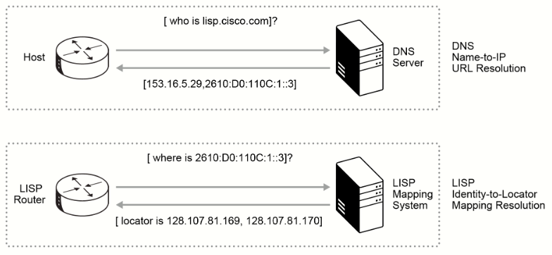
2. LISP Node Roles & Responsibilities
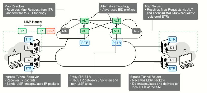
LISP deploys dynamic tunnels instead of requiring static preconfigured endpoints:
-
ITR (Ingress Tunnel Router): The entry point. It receives packets from local hosts, encapsulates them in LISP headers, and sends them toward the destination RLOC.
-
ETR (Egress Tunnel Router): The exit point. It receives encapsulated LISP packets from the core network, strips the LISP header, and delivers the raw packet to the destination EID.
-
xTR: A fabric switch running both ITR and ETR roles at the same time to allow bidirectional data flow.
-
Map Server (MS): The registry. Device to which LISP-site ETRs register their EID prefixes. The MS stores registered EID prefixes in a mapping database, where they are associated to RLOCs. All LISP sites use the LISP mapping system to resolve EID-to-RLOC mappings.
-
Map Resolver (MR): The directory. It receives queries (Map-Requests) from ITRs searching for the physical RLOC associated with a destination EID.
-
Proxy ITR (PITR): Provides connectivity between non-LISP sites and LISP sites by attracting non-LISP traffic that is destined to LISP sites and encapsulating this traffic to devices of ETR that are deployed at LISP sites.
-
Proxy ETR (PETR): Allows EIDs at LISP sites to successfully communicate with devices that are located at non-LISP sites.
-
Alternative Topology (ALT): A dedicated BGP-over-GRE overlay network used for aggregating EID prefixes and advertising them to Map Resolvers.
3. Control-Plane Flow (Registration & Resolution)
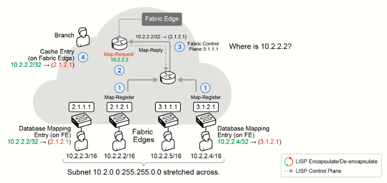
In Cisco SD-Access, control-plane traffic is optimized to minimize latency:
-
Onboarding: When an endpoint connects to a Fabric Edge, the Edge registers the device's EID and local RLOC with the Control Plane Node using a
LISP map-register. This builds the central host tracking database (HTDB). -
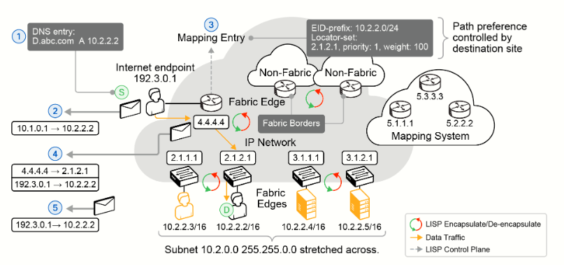
Querying: When a host (e.g., in a Branch) tries to communicate with a destination (e.g., 10.2.2.2), the local Fabric Edge sends a
LISP map-requestto the Control Plane. -
Proxy Reply: The Control Plane Node checks its database and sends a
proxy-replydirectly to the Branch Edge, providing the destination's RLOC (e.g., 2.1.2.1).-
Note: In legacy/standard LISP, the MR forwards the query to the destination edge, which replies. Cisco SD-Access optimizes this by having the Control Plane proxy-reply directly to reduce lookup delay.
-
4. Data Plane Forwarding Scenarios
Once the destination RLOC is cached in the Edge's CEF table, packets are encapsulated and transported via VXLAN.
A. Fabric Internal Forwarding (Edge-to-Edge)
-
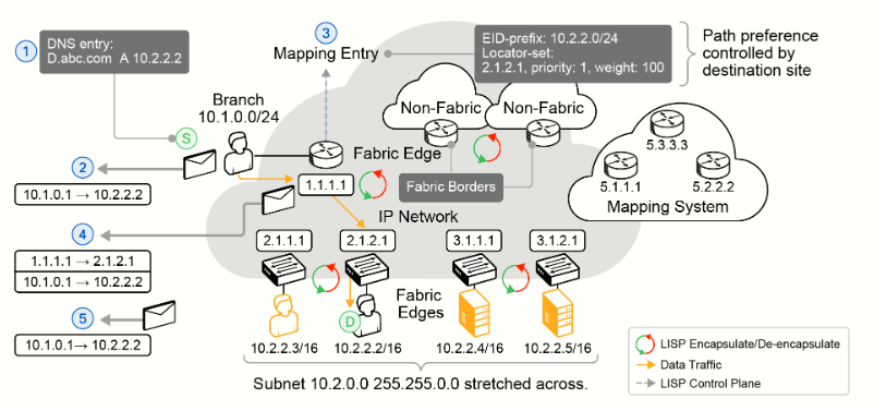
Goal: Host (10.1.0.1) wants to communicate with Web Server (10.2.2.2).
-
Step 1: The packet hits the local Branch Edge (RLOC: 1.1.1.1).
-
Step 2: The Branch Edge checks its map-cache, finding that 10.2.2.2 resides at RLOC 2.1.2.1.
-
Step 3: The Edge encapsulates the packet inside a VXLAN header:
-
Outer IP Header: Source:
1.1.1.1| Destination:2.1.2.1. -
Inner IP Header: Source:
10.1.0.1| Destination:10.2.2.2.
-
-
Step 4: The Destination Edge (2.1.2.1) receives the packet, strips off the VXLAN header, and delivers the raw packet to the Web Server.
B. External Forwarding (Border-to-Edge)
-
Goal: An external Internet client (192.3.0.1) sends traffic to Web Server (10.2.2.2).
-
Step 1: The traffic hits the Fabric Border (RLOC: 4.4.4.4).
-
Step 2: The Border checks its map-cache and finds Web Server (10.2.2.2) is behind Edge RLOC 2.1.2.1.
-
Step 3: The Border encapsulates the packet:
-
Outer IP Header: Source:
4.4.4.4| Destination:2.1.2.1. -
Inner IP Header: Source:
192.3.0.1| Destination:10.2.2.2.
-
-
Step 4: Destination Edge (2.1.2.1) de-encapsulates the VXLAN packet and forwards it to the Web Server.
5. Host Mobility (Dynamic EID Migration)
 |
|
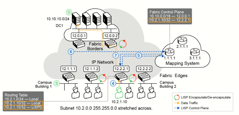
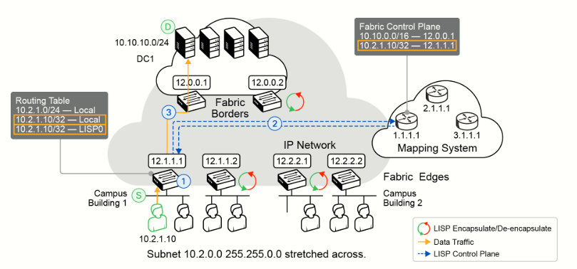
LISP dynamically tracks endpoints as they physically move across the network:
-
Initial Connection: Host (10.2.1.10) connects to Edge 1 (RLOC: 12.1.1.1). Edge 1 installs local host routes (including a local
/32andLISP0interface entry) and registers the host with the Control Plane. -
The Move: The host physically moves and connects behind Edge 2 (RLOC: 12.2.2.1).
-
Re-Registration: Edge 2 detects the host, installs local routing entries, and updates the Control Plane mapping database with the new RLOC (12.2.2.1).
-
Cache Invalidation: The Control Plane sends a message to the old Edge 1 (12.1.1.1) instructing it to clear its LISP cache entry for that endpoint.
-
Active Flow: Future traffic destined for the host is automatically encapsulated and routed to the new location (Edge 2).
6. Traditional LISP vs. Cisco SD-Access
Cisco SD-Access utilizes custom control-plane extensions to add advanced campus capabilities to standard LISP:
| Feature / Capability | Traditional LISP | Cisco SD-Access LISP Extension |
| Layer 2 Extension | Not supported. | Supported. Enables MAC-to-IP binding and Layer 2 overlays. Uses a prebuilt multicast underlay to distribute L2 broadcast/multicast (similar to VPLS). |
| Virtual Networks | Layer-3 (VRF) only. | Layer-3 (VRF) & Layer-2 overlays (using VXLAN). |
| Fast Roaming | Not supported. | Supported. Seamless endpoint roaming across the campus in < 50ms while retaining the same IP. |
| Wireless Extensions | Not supported. | Supported. The control plane fully integrates with wireless infrastructure for AP onboarding, Wireless Guest support, and running VXLAN straight to the AP. |