Lab 7-3: Configuring Call Detail Records and Accounting
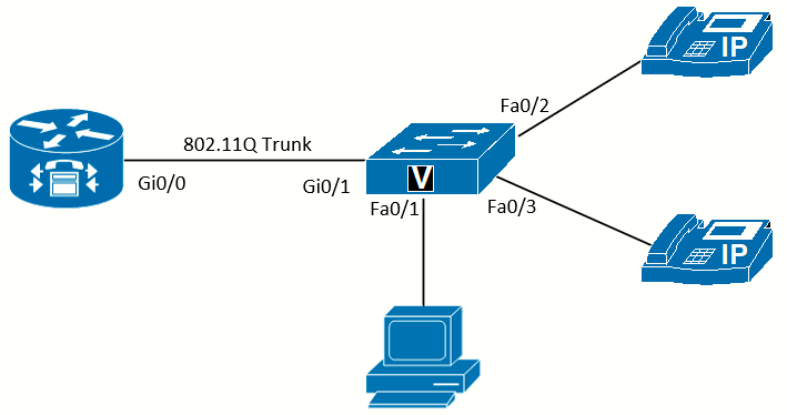 Topology diagram
Scenario
JRI needs to get information about calls placed on its phones. There might be a number of reasons for this, such as disputing with the service provider over billing, investigating improper use of long-distance and international calls, breaking billing costs out to department or user levels, and troubleshooting. Two related logging systems can provide this information: system event logging and call detail records (CDR). System event logging helps troubleshoot any number of problems with the networking gear, while call detail records contain information about each call going through the system. These messages can be sent to a local buffer on the device and to a syslog server.
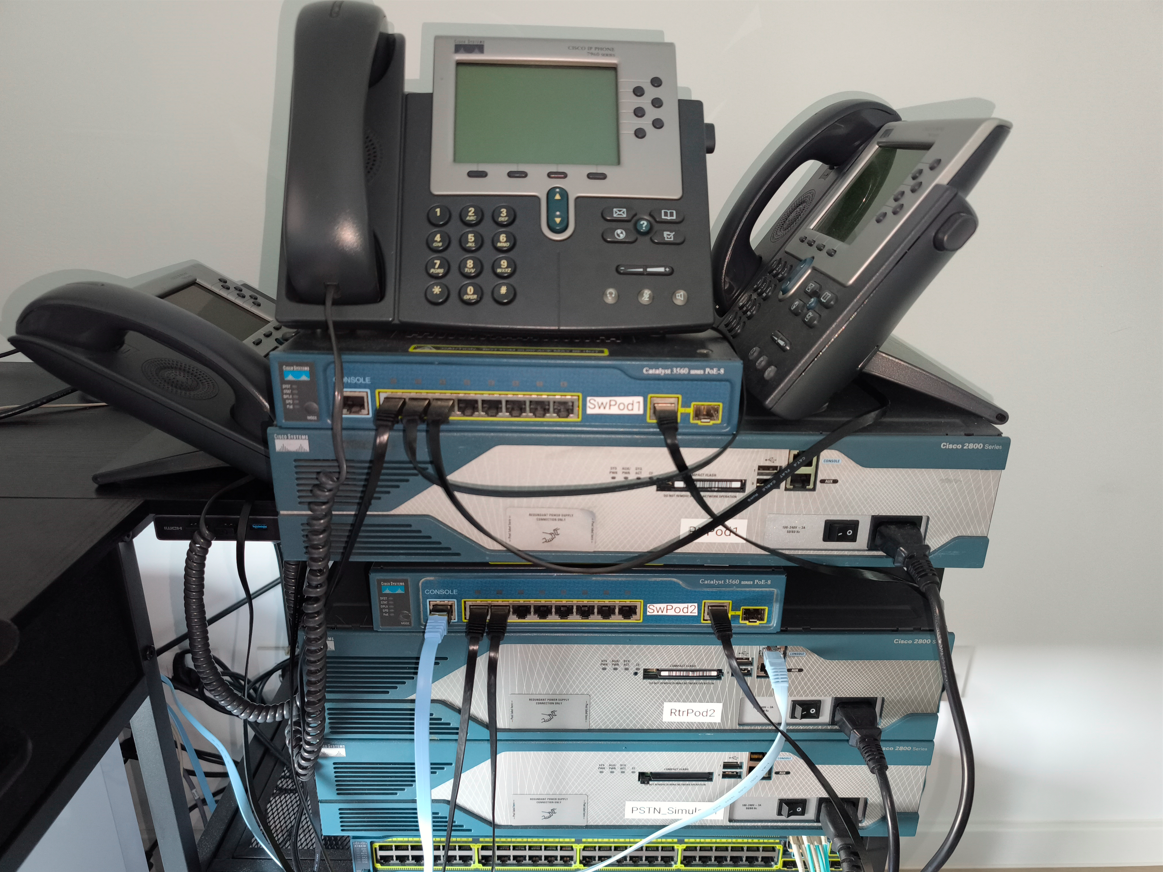
Equipment Required
- Cisco 2821 router
- Cisco 3560 switch
- Lab configuration from Lab 7-2.
- Two or more IP Phones
- PC running syslog software (such as Kiwi Syslog)
Objectives
- Examine call records on the router.
- Send call detail records and accounting to a syslog server.
Task 1: Load Prior Configurations
This lab is based on the configuration from Lab 7-2. If necessary, load the configuration for both the switch and router. Connect a PC to the switch and verify that it can ping the router and switch management addresses.
Task 2: Establish Logging Locally on the Router
While troubleshooting on a router, it can be handy to view the logs of recent events to gather information. All the event messages that show on the console can be sent to a local logging facility on the device, which is disabled by default. Although not absolutely necessary, having correct timestamps on events makes troubleshooting easier and is essential if the logs might ever be used for legal purposes. Enabling Network Time Protocol (NTP) (as shown in Lab 3-2) allows the device to have accurate time. The timestamps for system events can then be set to use the local time zone using the service timestamps command with the localtime keyword.
To enable logging, the size of the buffer to store messages (which impacts memory usage) must be determined using the logging buffered command:

Now that logging is established, generate a log message by exiting configuration mode:
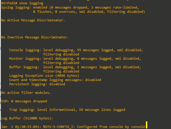
The logging buffer will get the same messages the console receives, and it will show messages regarding calls that use the ISDN PRI. However, these messages are the result of the ISDN PRI interface activity. If you make a call between IP Phones, there are no logged messages. This is where CDRs enter the picture.
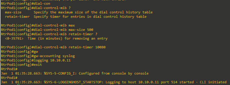
Task 3: Establish Logging and CDRs to a Syslog Server
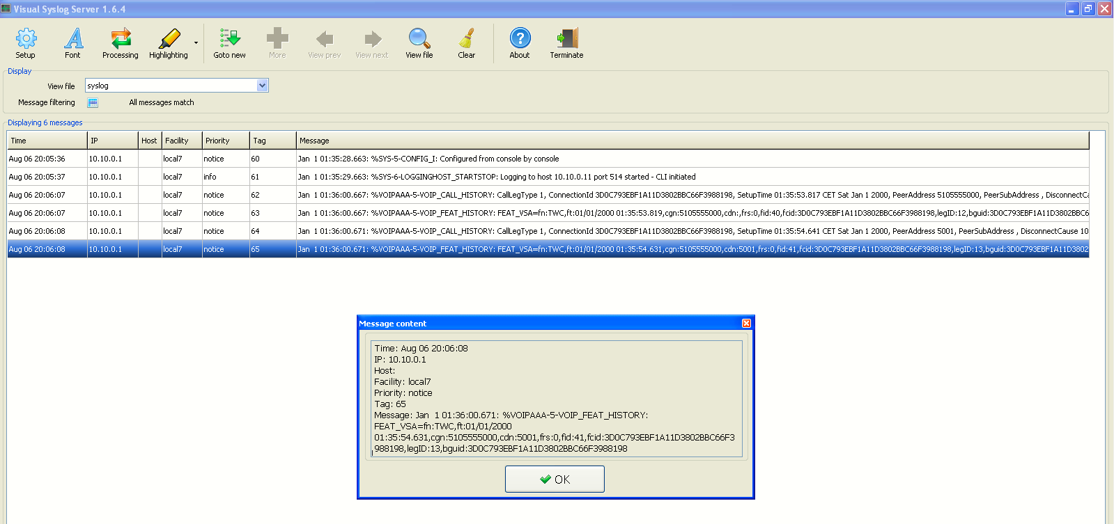
There are advantages to having logging messages sent to an external syslog server. On a syslog server, scripts can be used to filter the output, and there is no risk of losing the records when the device loses power. Additionally, the CDRs can be sent to a syslog server (RADIUS and FTP are two other options) for detailed billing information and call tracing. Establishing CDRs is done with the dial-control-mib command, with the maximum number of entries to retain using the max-size keyword and how long to keep the records using the retain-timer keyword. The gw-accounting syslog command tells the system to send CDRs to a syslog server, and the logging command specifies the IP address of the syslog server.
Now make a call from IP Phone 1 to IP Phone 2. The syslog server should receive the CDR, as shown in the image below (I used Visual Syslog installed on a Win XP VM).
This is the last lab configuring CUCME until troubleshooting is discussed in Lab 15-1.