Lab 6-2: Configuring Digital Interfaces
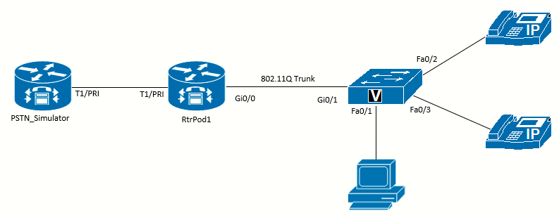 Topology diagram for this lab
Scenario
JRI expects to have enough incoming and outgoing calls that it want to use a digital connection to the PSTN. Not only do digital connections provide a trunk with 23 (PRI), 24 (T1), or 30 (E1) simultaneous calls on a single cable, but they also have enhanced features, such as Direct Inward Dialing (DID), that allow the PSTN to signal the extension that the incoming call should be connected to. There are two types of signaling: common channel signaling (CCS), and channel associated signaling (CAS, aka. robbed-bit signaling). There are two types of time-division multiplexing (TDM), which impact the number of channel available. The T1 format is common in the US and Japan (24 channels), and E1 is common elsewhere (32 channels).
Equipment Required
- Cisco 2821 router (RtrPod1)
- Another Cisco 2821 router with a T1/E1/PRI Trunk (PSTN_Simulator)
- DSP resources in both routers (PVDM chips) to enable the Multiflex Trunk
- Cisco 3560 switch
- Lab configuration from Lab 6-1
- Two or more IP Phones
- T1/E1/PRI Multiflex Trunk Voice WAN Interface Cards (VWIC) card or NM (Network Module)
Older digital T1 interfaces such as the DSU-T1 WAN Interface Cards (WICs) will not work for VoIP on the router. To work with VoIP traffic, a Multiflex VIC (Voice Interface Card) that supports both voice and data is required. These cards also require DSP resources
Objectives
Upon completion of this lab, you will be able to configure the basics of T1/E1/PRI interfaces.
Task 1: Load Prior Configuration and have the PSTN_Simulator configured
This lab is based on the configuration from Lab 6-1. If necessary, load the configuration for both the switch and router. Connect a
PC to the switch and verify that it can ping the router and switch management addresses. Connect the VoIP phones and verify that you can call between them.
Also, we need to set up the PSTN_Simulator 2821 router to follow through this lab. This is configured in Appendix E.
Task 2: Examine Resources in the Router
Examine Hardware
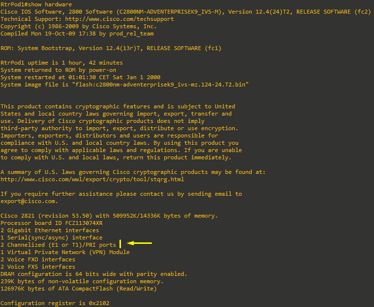
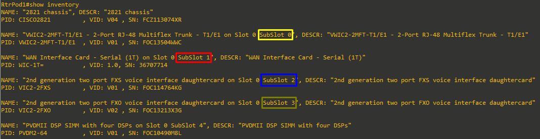
Use the show hardware command to examine the interfaces available in RtrPod1. In the output, you should see the model of your router and the amount of memory installed, followed by a listing of the interfaces installed. You are looking for a line like one (or more) of the following:
- 1 Channelized/Clear T1/PRI port
- 1 Channelized/Clear E1/PRI port
- 1 Channelized (E1 or T1)/PRI module
Command executed on the RtrPod1 Cisco 2821 router:
If you see the last option from the previous bullets, as I do on the output above, or if the running-config includes a comment that starts with ! card type command needed for,
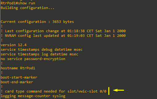
then it means we have a newer VWIC (such as the VWIC2-2MFT-T1/E1 card, like I do) that will support either a T1 or an E1, and you must select which mode to use before you can complete the following steps:

The command to select a T1 (which is the mode we will use in this lab) is:
RtrPod1(config)#card type t1 0 0Examine Controller Interface
We can test the T1 connected to another device's T1/E1 interface (PSTN_Simulator) using a T1 crossover cable to keep the interface up. Assuming the PSTN_Simulator router has been already configured, after the cable is connected between both routers, the amber Alarm LED will be lit if the two cards are not configured the same, and just the green Carrier Detect (CD) LED will be lit if the carrier is present.
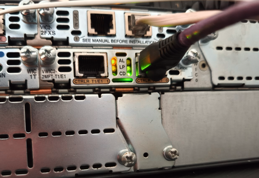 CD led is lit for the carrier is present (controller 0/0/0)
A T1 crossover cable is not the same as an Ethernet crossover cable. T1 crossover cables have a different pinout. They are not difficult to make if you have cable-making supplies, or they can be purchased premade. More info here.

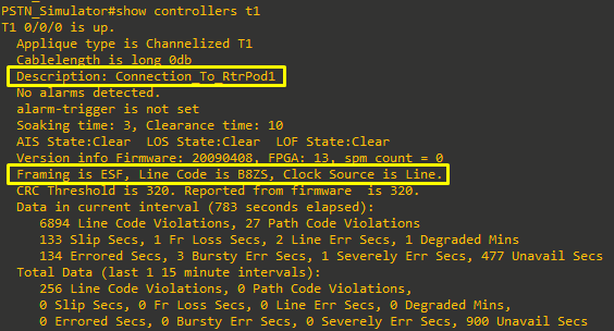
The capture above shows the output on the PSTN_Simulator router at the moment the VWIC is configured. If it's not configured with the card type command, the interface will not come up! (at least if using the newer VWIC2-2MFT-T1/E1 as in this case). Also, supposing we configured the card as E1 on one end and T1 on the other end, the interface won't come up.
The output of the show controllers t1 below on the PSTN_Simulator router, shows the default configuration of the interface, as configured on Appendix E:
Examine DSP Resources
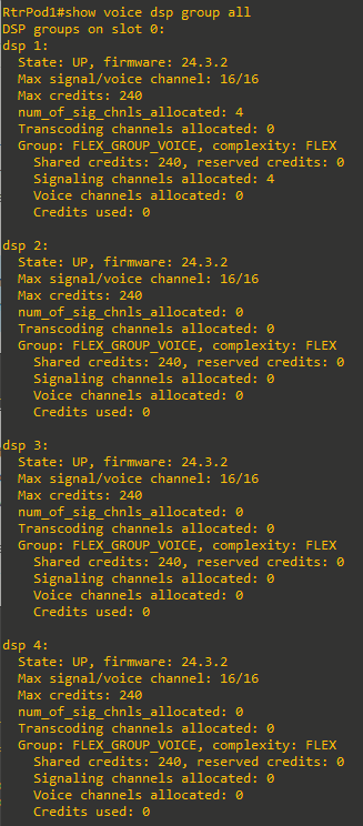
DSP resources need to be available in your system to configure the interface. The number of resources can be examined using the show voice dsp group all command. In the following output, the RtrPod1 router has a PVDM2-64 card installed.
Cisco’s PVDM2‑64 isn’t a single monolithic DSP engine, but rather four independent DSP “slices” (each handling up to 16 channels) packaged on one card. When you run show voice dsp group all, IOS shows you each slice as its own “DSP group” – hence you see dsp 1, dsp 2, dsp 3 and dsp 4, each with a 16‑channel capacity.
Four of the channels are already in use for the two FXS and two FXO ports, leaving 12 channels on the first DSP group. A full T1 PRI will need 23 channels. If there are fewer resources available than required, either more DSPs are required or a fractional PRI will need to be configured.
Task 3: Configure CCS (PRI) Settings
BRI (Basic Rate Interface) provides two 64 kbps B‑channels for voice/data and a 16 kbps D‑channel for out‑of‑band signaling, making it ideal for small sites, while PRI (Primary Rate Interface) aggregates 23 (T‑1) or 30 (E‑1) B‑channels with a 64 kbps D‑channel for larger PBX trunks at 1.544 Mbps or 2.048 Mbps. Both use CCS (Common Channel Signaling) over the dedicated D‑channel to carry advanced call‑control features without “stealing” voice bits, whereas CAS (Channel‑Associated Signaling) embeds basic on‑hook/off‑hook or wink‐start signals in each voice timeslot, reducing voice quality and limiting features but offering a simple, legacy alternative.
So, the most common signaling for a digital voice trunk is CCS with ISDN PRI as the protocol. The output in this task shows configuring a T1 line as an ISDN PRI.
We will need to configure the RtrPod1 (the PSTN_Simulator was already configured as per Appendix E). The configurations must match on both routers.
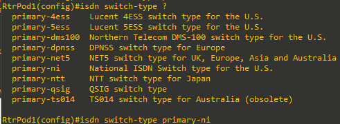
Configure ISDN Switch Type
The first step when configuring a PRI is to select the type of switch the service provider used. For the lab, since we're connecting to another Cisco router (PSTN_Simulator), use the primary-ni option in both routers, which is useful:
-
In CCNA/CCNP labs — guaranteed to interoperate on two IOS routers without any telco‑specific oddities.
-
In vendor‑neutral testbeds where you want minimal footguns.
Configure Clock Participation
The network-clock-participate command is used to keep multiple interfaces synchronized to the same clock signal. For 2821 routers use the following (in this case we have the T1/E1 WIC installed on physical subslot 0):
RtrPod1(config)#network-clock-participate wic 0The 2800 Series require this command.
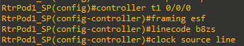
Configure Controller T1 Settings
The next step is to configure the settings on the T1 controller (even though we are configuring the interface as an ISDN PRI, it is still a T1 interface). The framing, line coding, and clock source should be configured to match the service provider (PSTN_Simulator).The most common settings in the US are ESF for framing and B8ZS for line coding. For a connection to a SP, the clock source should be set to line, but if the router is connected to a PBX, the router might need to provide the clocking, and then the clock source should be internal.
Configure PRI Timeslots
There are two limiting factors that control how many timeslots can be allocated. The first is the number of channels the service provider has allocated. With fractional PRI service, the service provider only allocates the number of channels the company (customer) pays for. If you allocate more channels than the provider allocated, calls on the extra channels will not complete. The second limit is the amount of DSP resources available in your system. For example, if you try to configure all 23 channels of a PRI, but only have enough DSP resources for 16 channels, you will get the following messages:
% Not enough DSP resources available to configure pri-group on controller T1 0/0/0
% The remaining dsp resources are enough for 16 time slots.
% For current codec complexity, 1 extra dsp(s) are required to create this voice
port.
Before configuring the timeslots on your system, determine the number of channels that both systems can be configured to use and what resources are available. In my case, both 2821 routers have a PVDM2-64 each. The first router RtrPod1 has already four channels configured as explained above on Task 2, so both ends will be configured to match using pri-group timeslots 1-4. When the command is issued, the four channels will be created:
RtrPod1(config-controller)#pri-group timeslots 1-4
RtrPod1(config-controller)#
Jan  1 00:21:42.675: %LINK-3-UPDOWN: Interface ISDN-VOICE 0/0/0:23(1), changed state to up
Jan  1 00:21:42.675: %LINK-3-UPDOWN: Interface ISDN-VOICE 0/0/0:23(2), changed state to up
Jan  1 00:21:42.675: %LINK-3-UPDOWN: Interface ISDN-VOICE 0/0/0:23(3), changed state to up
Jan  1 00:21:42.675: %LINK-3-UPDOWN: Interface ISDN-VOICE 0/0/0:23(4), changed state to up
RtrPod1(config-controller)#
Jan  1 00:21:43.655: %LINEPROTO-5-UPDOWN: Line protocol on Interface Serial0/0/0:0, changed state to down
Jan  1 00:21:43.659: %LINEPROTO-5-UPDOWN: Line protocol on Interface Serial0/0/0:1, changed state to down
Jan  1 00:21:43.659: %LINEPROTO-5-UPDOWN: Line protocol on Interface Serial0/0/0:2, changed state to down
Jan  1 00:21:43.659: %LINEPROTO-5-UPDOWN: Line protocol on Interface Serial0/0/0:3, changed state to down
Jan  1 00:21:43.659: %LINEPROTO-5-UPDOWN: Line protocol on Interface Serial0/0/0:23, changed state to up
RtrPod1(config-controller)#
Jan  1 00:21:44.667: %LINK-3-UPDOWN: Interface Serial0/0/0:23, changed state to up


PSTN_Simulator(config-controller)#pri-group timeslots 1-4
PSTN_Simulator(config-controller)#
*Jan  1 00:47:09.067: %LINK-3-UPDOWN: Interface ISDN-VOICE 0/0/0:23(1), changed state to up
*Jan  1 00:47:09.071: %LINK-3-UPDOWN: Interface ISDN-VOICE 0/0/0:23(2), changed state to up
*Jan  1 00:47:09.071: %LINK-3-UPDOWN: Interface ISDN-VOICE 0/0/0:23(3), changed state to up
*Jan  1 00:47:09.071: %LINK-3-UPDOWN: Interface ISDN-VOICE 0/0/0:23(4), changed state to up
PSTN_Simulator(config-controller)#
*Jan  1 00:47:10.035: %LINEPROTO-5-UPDOWN: Line protocol on Interface Serial0/0/0:0, changed state to down
*Jan  1 00:47:10.039: %LINEPROTO-5-UPDOWN: Line protocol on Interface Serial0/0/0:1, changed state to down
*Jan  1 00:47:10.039: %LINEPROTO-5-UPDOWN: Line protocol on Interface Serial0/0/0:2, changed state to down
*Jan  1 00:47:10.039: %LINEPROTO-5-UPDOWN: Line protocol on Interface Serial0/0/0:3, changed state to down
*Jan  1 00:47:10.043: %LINEPROTO-5-UPDOWN: Line protocol on Interface Serial0/0/0:23, changed state to up
PSTN_Simulator(config-controller)#
*Jan 1 00:47:11.047: %LINK-3-UPDOWN: Interface Serial0/0/0:23, changed state to up- This command activates timeslots 1 through 4 as an ISDN PRI group.
- 4 B-channels are created (0-3)
- 1 D-channels is automatically activated (channel 23 due to T1 being configured).
Examine the Interfaces
Now that the PRI is configured, examine the changes to the router. Start with the show isdn status command to verify L1 is active and L2 is Established:
|
|
|
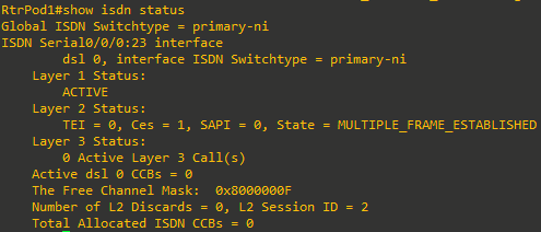
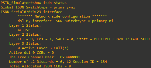
We can see on the output from the command on both routers that L1 is ACTIVE and that L2 is in the state MULTIPLE_FRAME_ESTABLISHED (D‑channel signaling link is fully up and running, ready to carry Q.931 call‑control messages).
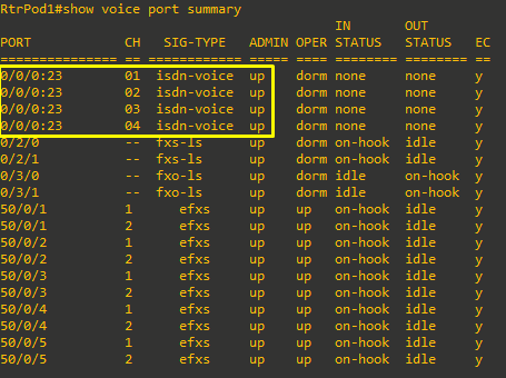
Then, look at the output of the show voice port summary command. Notice in the following output that the signaling port is 0/0/0:23 with 4 channels. While the 24th channel is used for signaling, Cisco starts interface numbering with 0, so it becomes channel 23 in the interface output:
Task 4: Configure ISDN Network End
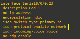
This step can be avoided if the PSTN_Simulator router is already configured as per Appendix E. However, you can read it as a reference for why the isdn protocol-emulate network command is used.
In the same way that connecting two routers back to back in a lab with a serial cable required one of them to be the data communications equipment (DCE) and provide the clocking, ISDN needs one of the devices to act as the network end to match the subscriber end. Configuring a Cisco router to act as the service provider equipment could also be done to provide a connection to a PBX.
The PSTN_Simulator router's signaling channel should be configured with the isdn protocol-emulate network command. This makes the PSTN_Simulator router take the role of service provider.