
Lab 6-6: Dial-Peer Configuration Using CCP
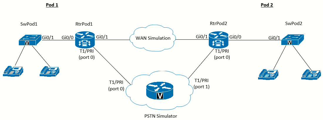 Topology diagram for this lab
Scenario
Jimenez Research Inc. (JRI) wants to connect to customers using the PSTN and remote branch offices of the company using the WAN. To avoid WAN failure from disabling four-digit dialing between locations, call failover from the WAN to the PSTN needs to be configured.
Equipment Required
- Two Cisco 2821 routers with voice IOS (RtrPod1 and RtrPod2).
- Two Cisco 3560 switch (SwPod1 and SwPod2).
- Cisco 2821 router configured as PSTN_Simulator (see Appendix E).
- T1/E1/PRI Multiflex Trunk VWIC cards or Network Modules.
- DSP resources in the routers (PVDM chips) to enable the Multiflex Trunk.
Objectives
- Configure dial peers to connect to the PSTN.
- Configure dial peers to connect to remote offices using the WAN.
- Configure failover for calls to remote offices using the PSTN when the WAN is down.
Task 1: Load Prior Configurations
This lab is based on the configuration from Lab 6-2. If necessary, load the configuration for both the switch and router.
Task 2: Configure Digital T1/E1/PRI Interface
If using a T1/E1/PRI interface that has not been configured, follow these instructions. It is assumed Lab 6-5 has been completed before doing this lab. Both labs are essentially the same with this one using the CCP instead the CLI to configure the devices. Also, the only device that will be configured via CCP in this lab is RtrPod1. RtrPod2 will keep its configuration from Lab 6-5.
Digital Trunks
Use the community created in Lab 4-1 Task 3 to connect to RtrPod1. With the router discovered, click Configure. The pane on the left will show various categories of router configuration options. The items you see will depend on the IOS you have installed.
Click the Unified Communications folder icon to expand the subitems.
Click the Trunks folder icon to expand the subitems, and click the Digital Trunks subitem. In the Digital Trunks pane on the right is a table showing any T1/E1 interfaces.
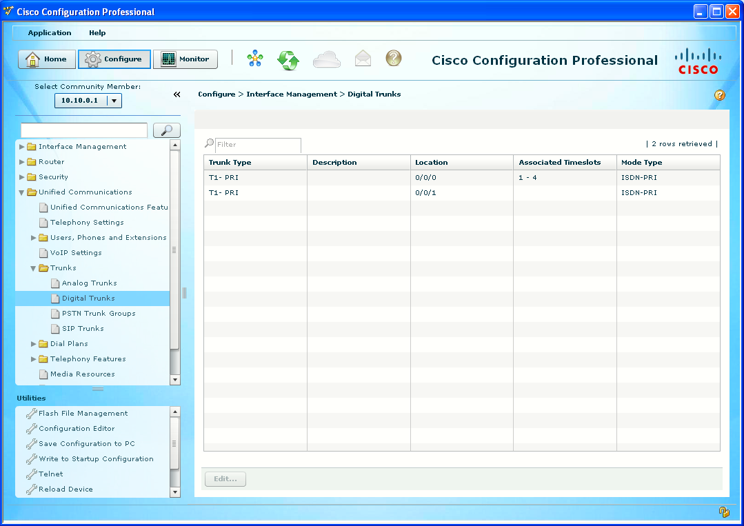
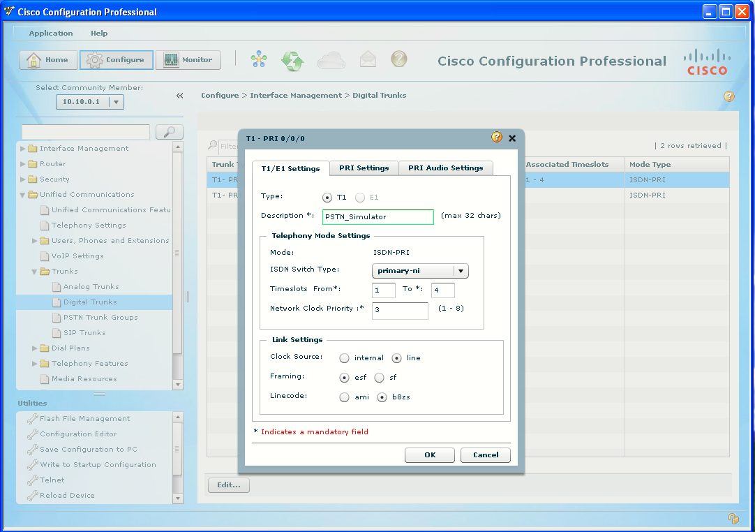
Double click the desired trunk (we will use 0/0/0 since it will be the connection to the PSTN_Simulator).
- Enter PSTN_Simulator or the like as the description.
- Timeslots From: 1 to 4 (default, see Appendix E and previous labs).
- Clock Source -> line
Then deliver the configuration.
Now cable Pod 1 and Pod 2 to the PSTN_Simulator using PRI crossover cables, as in Lab 6-5. Devices should be wired as per the diagram above.
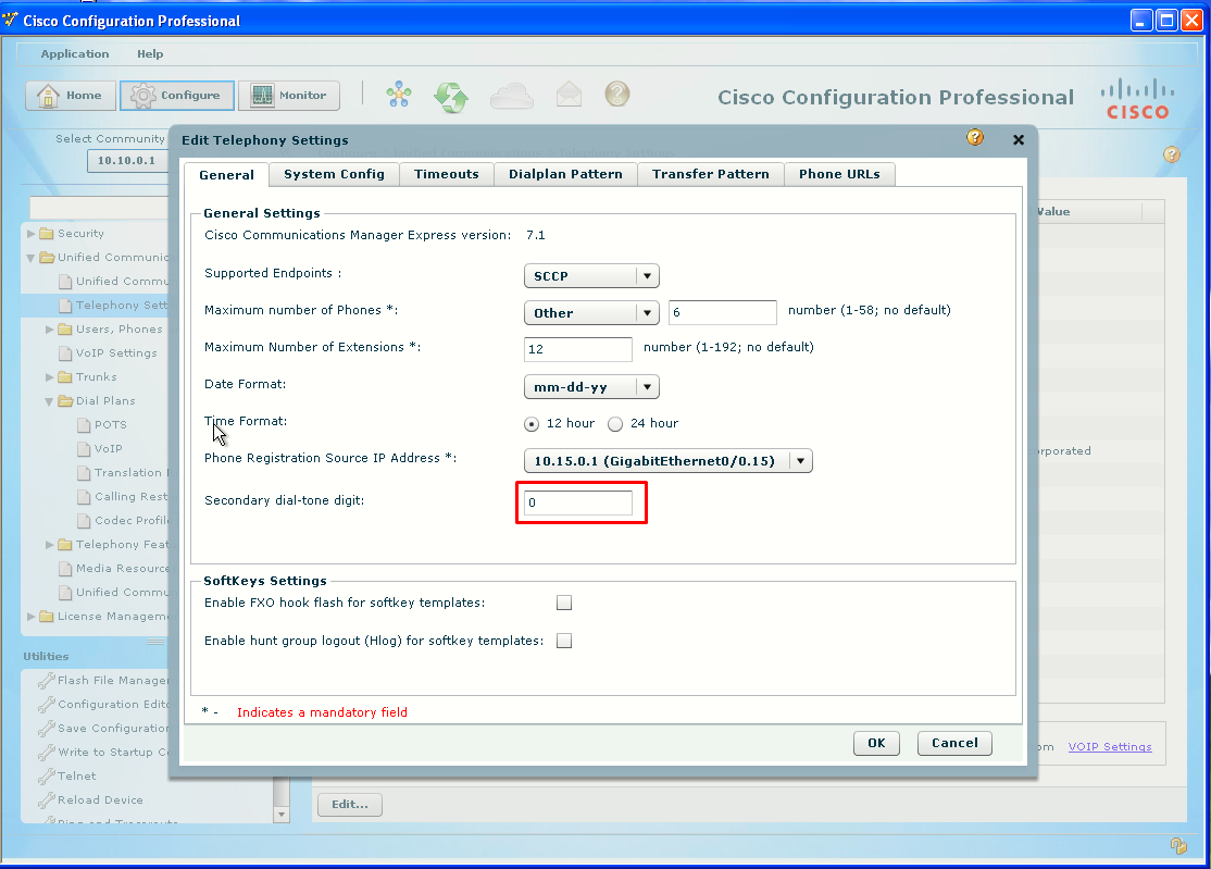
Task 3: Configure Secondary Dial Tone
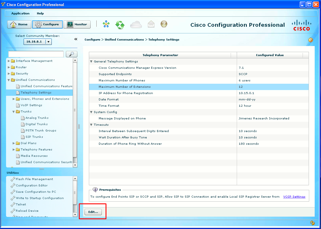
This secondary dial tone for outside lines can be configured under the Unified Communications > Telephony Settings subitem.
Task 4: Create Outgoing Dial Plan
CCP is able to import templates to quickly create dial plans for various countries. After importing a country-specific set of dial peers, you can customize them to suit your needs.
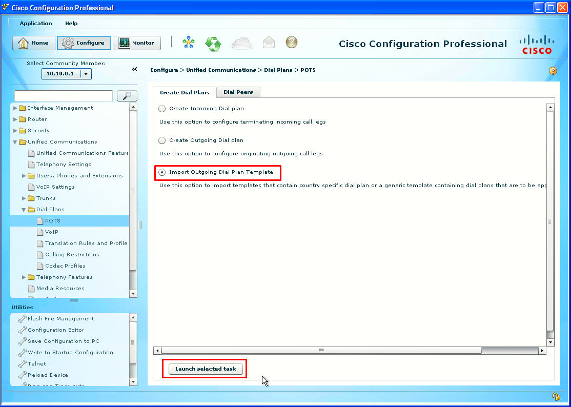
POTS Dial Plans
Under the Unified Communications > Dial Plans > POTS subitem, in the Create Dial Plans tab, click the Import Outgoing Dial Plan Template radio button. And click Launch selected task.
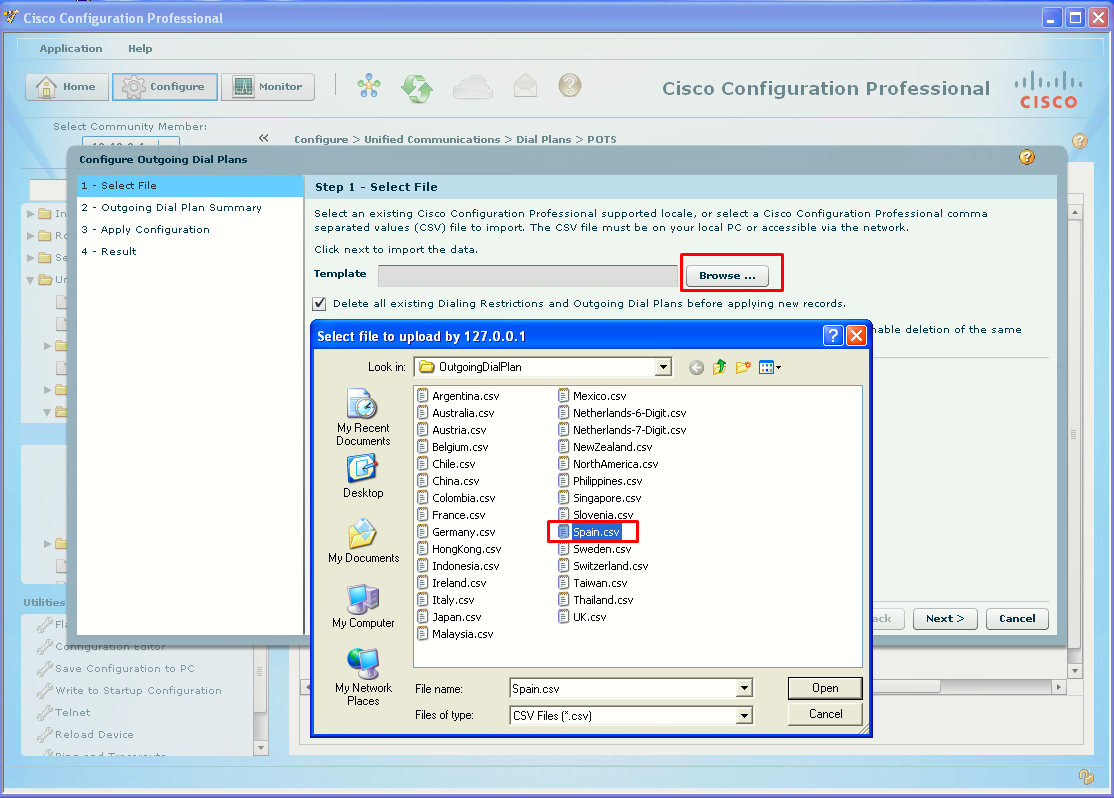
Import Outgoing Template
The Configure Outgoing Dial Plans dialog box will open to Step 1 - Select File. Click the Browse button, and navigate to the templates folder (default location is C:\Program Files\Cisco Systems\CiscoCP\template\OutgoingDialPlan). I will import Spain dial plan:
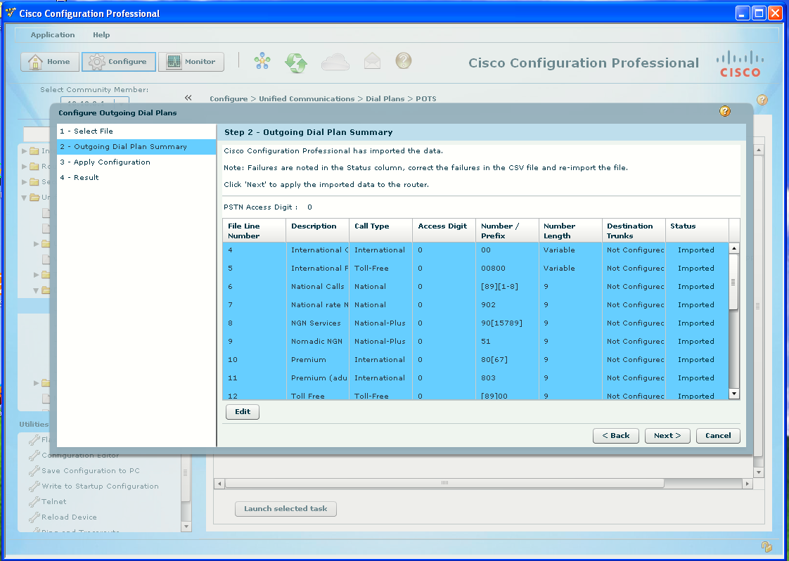
Outgoing Dial Plan Summary
The Step 2 – Outgoing Dial Plan Summary dialog box shows the dial peers that will be created. Notice that all the dial peers have Not
Configured in the Destination Trunks fields. To save time selecting the trunk, click the first dial peer and then scroll down and press Ctrl+Shift while clicking on the last dial peer to change all of them at once.
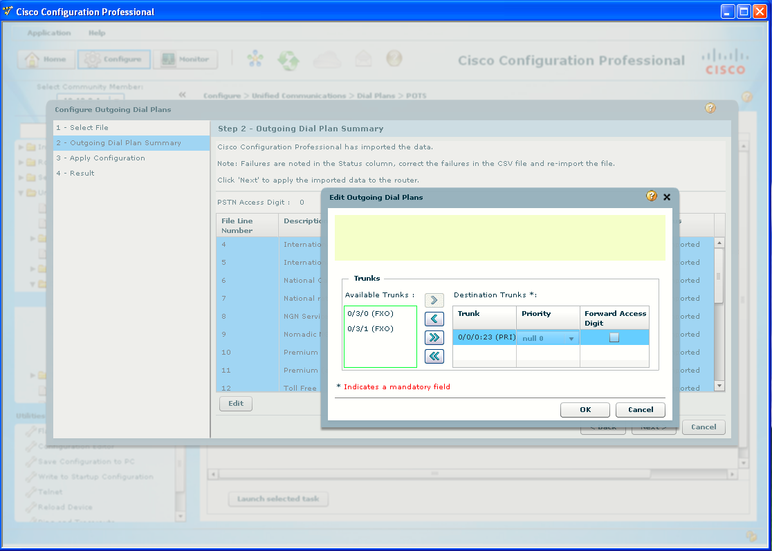
Selecting Destination Trunk
The Edit Outgoing Dial Plans dialog box shows a list of available trunks. Under the Available Trunks, click the PRI interface interfaces and then click the arrow (>) button to move the selection to the Destination Trunks list.
Apply Configuration
The Step 3 – Apply Configuration dialog box will process the configuration changes. Do not be alarmed if the progress bar does not show all items processed, as long as there are no failures. The Step 4 – Result dialog box will open. Click the Finish button.
Task 5: Create Outbound POTS Dial Peers
After importing a country-specific set of dial peers, you can customize them to suit your needs. It is also good to know how to manually add and edit dial peers without using the wizard.
View POTS Dial Peers
Under the Unified Communications > Dial Plans > POTS subitem, click the Dial Peers tab, which lists all the existing dial peers.
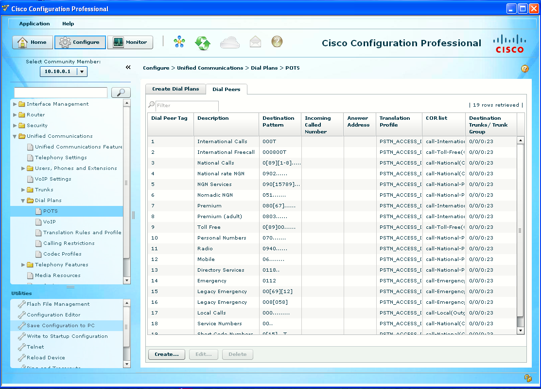
Beware the template is using 0 as the access digit, default for the Spain template. In Lab 6-5 we used 9.
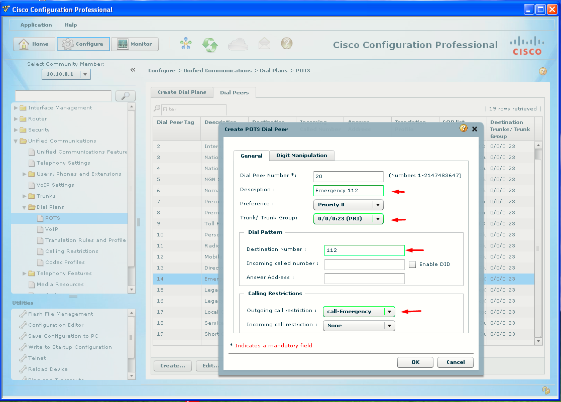
Create POTS Dial Peer Example
Click the Create button at the bottom of the dialog box. The Create POTS Dial Peer dialog box will open to the General tab. Refer to the image below to see what has been configured to create a dial peer for the 112 calls.
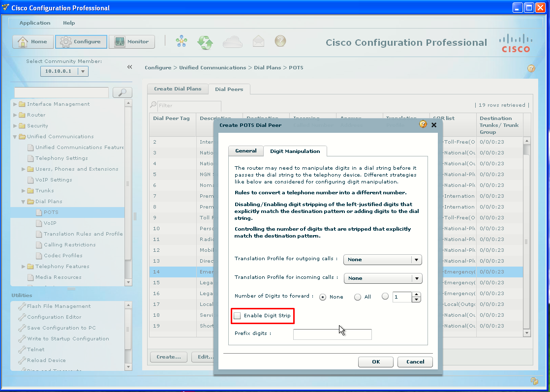
Digit Manipulation
As discussed in Lab 6-4, Task 2, POTS dial peers have digit stripping by default. CCP automatically configures the dial peer to strip only the outside line access digit. However, in this case, the goal is to configure 911 without an access digit. If you just left the default configuration, the 0 would be stripped and only the 11 would be sent to the PSTN. Click the Digit Manipulation tab to see the defaults. Click to deselect the Enable Digit Strip check box.
Deliver the configuration.
Make Test Calls to the PSTN Simulator
Use the test numbers as in Lab 6-5 to place calls from an IP Phone to the PSTN Simulator. I will use the 0 to get an outside line first. The PSTN simulator will play a different sound file for each test number listed.
Task 6: Create Incoming Dial Plan
CCP has a wizard to quicly create an incoming dial plan.
Create Dial Plans Wizard
Under the Unified Communications > Dial Plans > POTS subitem is the Create Dial Plans tab. Click the Create Incoming Dial plan
radio button (if it is not already selected), and click the Launch selected task button at the bottom of the window.
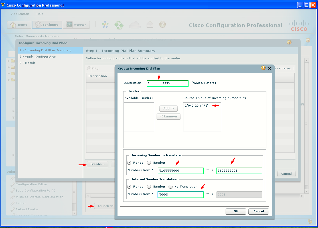
The Configure Incoming Dial Plans dialog box will open to Step 1 – Incoming Dial Plan Summary. Click the Create button. The Create Incoming Dial Plan dialog box will open.
- Enter Inbound PSTN the Description field.
- Under the Available Trunks, click the PRI interface and then click the Add button to move the selection to the Source Trunks of Incoming Numbers list.
- Enter the full range of phone PSTN numbers for the pod (Pod 1 here). If using the PSTN simulator, as I do, the numbers should be ten digits long.
- Enter the first four-digit extension for Pod 1 in the Numbers From field, under Internal Number Translation.
- Click OK and finish applying the configuration through the wizard.
Task 7: Create VoIP Dial Peers
To send calls over an IP-based network, VoIP dial peers are used. VoIP dial peers are ideal for calls between locations over a WAN.
Configure a WAN Connection
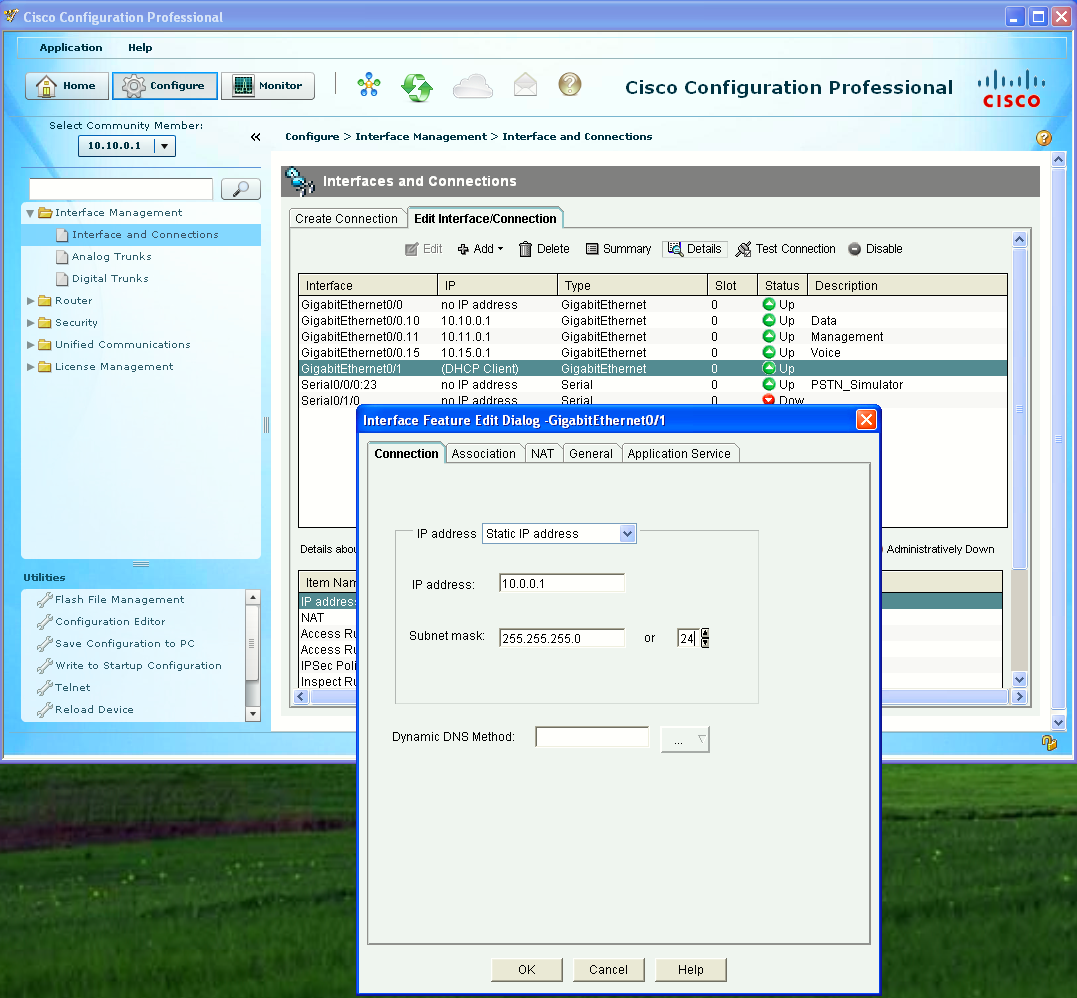
Connect Pod 1 and Pod 2 using an Ethernet cable on port Gi0/1. The WAN connection on Gi0/1 can be configured using CCP in the Interface Management > Interfaces and Connections subitem. Use the 10.0.0.0/24 network for the WAN and configure the Gi0/1 interface with IP address 10.0.0.1/24 (Pod 1) and 10.0.0.2/24 (Pod 2) as in Lab 6-5.
Create VoIP Dial Peers
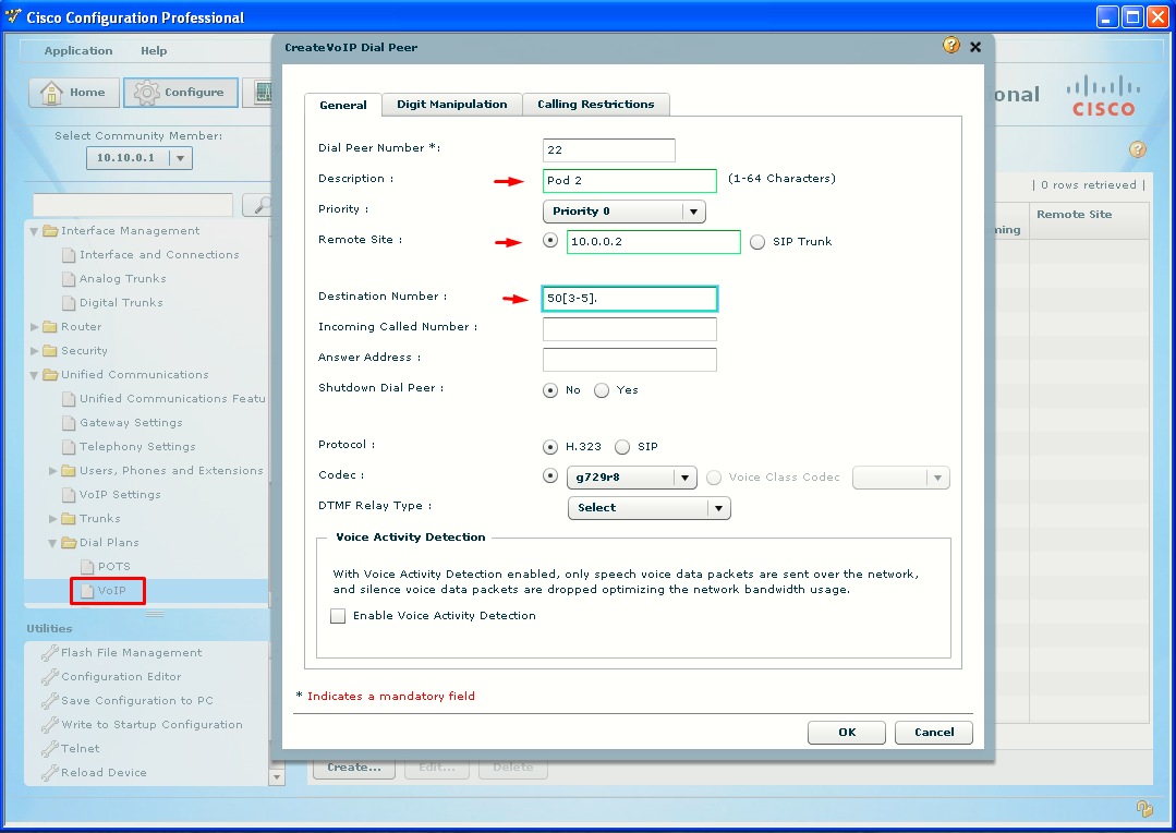
Click the Unified Communications > Dial Plans > VoIP subitem. Click the Create button at the bottom of the pane.
The Create VoIP Dial Peer dialog box will open to the General tab.
- Enter a description for the dial peer (use the name of the remote pod this dial peer will connect to, i.e Pod 2).
- Enter the IP address of the remote pod (Pod 2) in the Remote Site field.
- Enter the four-digit extension range of the remote pod (using wildcards) in the Destination Number field.
Unlike POTS dial peers, VoIP dial peers do not have automatic digit stripping, so there is no need to use the Digit Manipulation tab. Deliver the configuration, and verify that you can call extensions in other pods by dialing just the four-digit extension.
Task 8: PSTN Failover
As noted in Lab 6-5, after users get accustomed to dialing four-digit extensions for other people in the company, a WAN failure will result in call failure, even though the PSTN connection is still working. PSTN failover allows the users to successfully dial the four-digit internal extensions even when the WAN is down; the calls are redirected using the PSTN. As noted in Lab 6-4, Step 1-1, Rule 4, when two dial peers have the exact same destination pattern, they are selected at random. However, this can be controlled using the preference command. The higher the preference value, the less desirable the dial peer is. All dial peers have a default preference of 0. By creating a POTS dial peer that has the exact same destination pattern as the VoIP dial peer, but assigning a preference greater than 0, the VoIP dial peer will be preferred as long as the WAN is up. If the WAN fails, the router then looks for duplicate destination patterns with higher preferences.
Configure a POTS Dial Peer for Failover
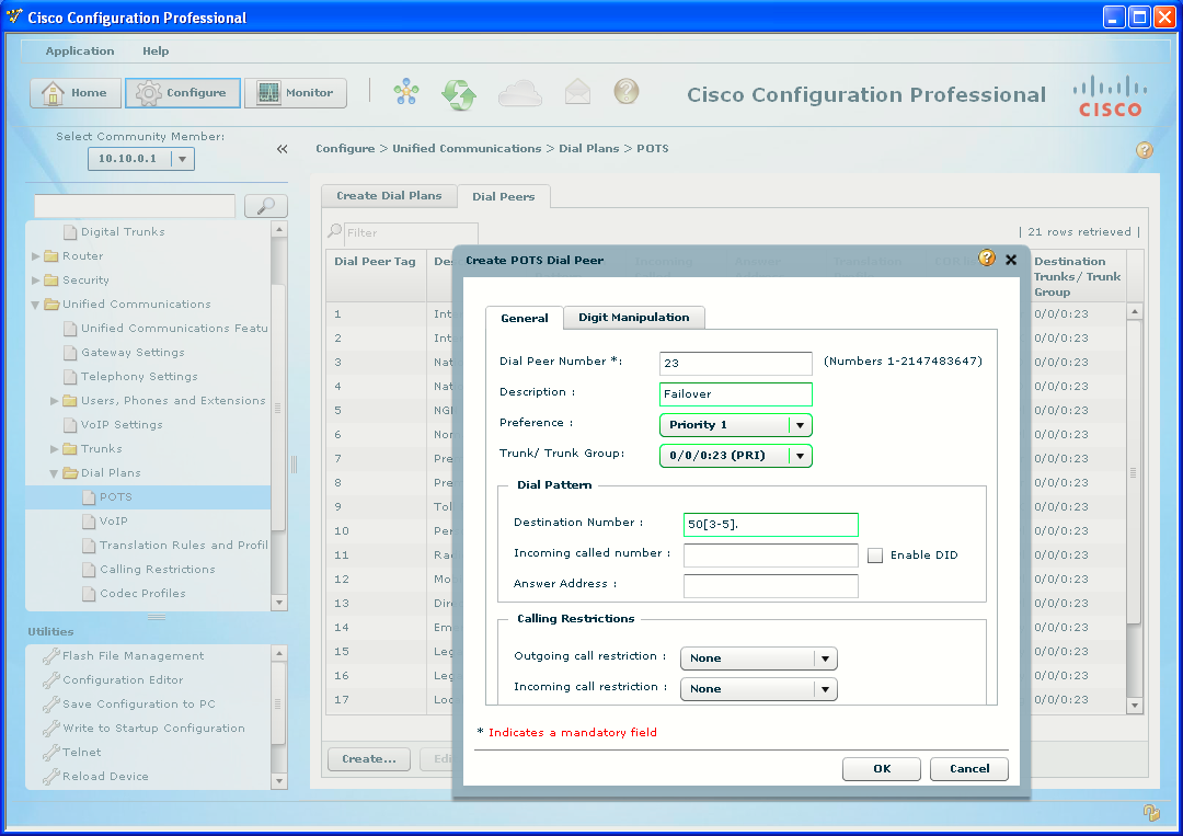
Under the Unified Communications > Dial Plans > POTS subitem, click the Dial Peers tab, which lists all the existing dial peers. Click the Create button at the bottom of the dialog box.
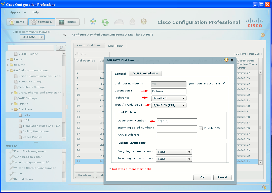
The Create POTS Dial Peer dialog box will open to the General tab.
- Enter a description for the dial peer (add Failover to the name of the remote pod this dial peer will connect to, i.e Pod 2).
- From the Preference pull-down menu, select Priority 1.
- Select the PRI interface.
- Enter the 4-digit range (using wildcards) of the remote pod (Pod 2) in the Destination Number field. Note: This should be exactly the same as was used in the VoIP dial peer.
Digit Manipulation
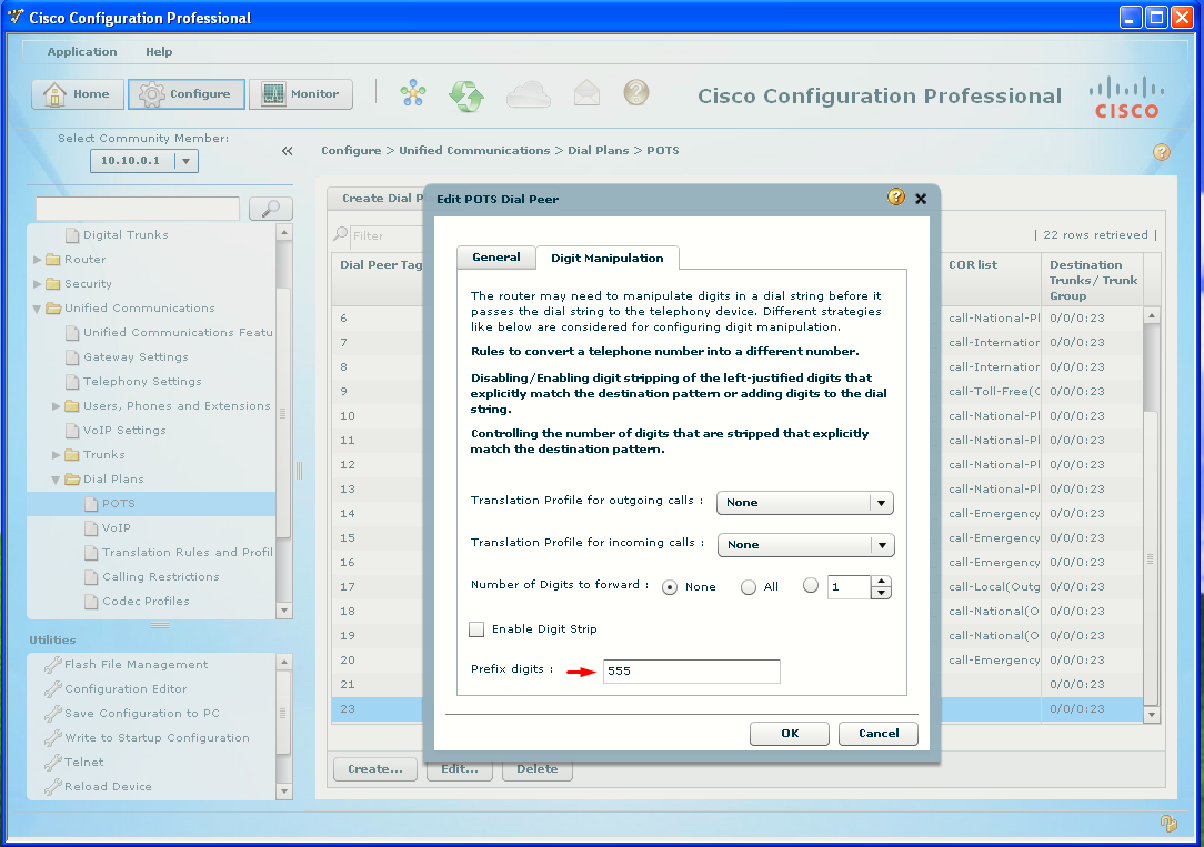
The only other thing to remember is that simply sending the remaining digits (after the default POTS digit-stripping behavior) will not be enough for the PSTN to route the call. This is where the prefix command is so useful. Not only can the stripped digits be preserved, but the other digits needed to complete the call can also be added to make a routable PSTN number (the same as if the call was dialed directly on a phone through the PSTN).
Click the Digit Manipulation tab. Deselect the Enable Digit Strip check box (which will preserve the 50 from being stripped), and in the Prefix Digits field, enter the necessary digits to allow the call to complete over the PSTN. For example, Pod 2 is at numbers 5555030 to 5555059, and the 5030 to 5059 is part of the dial peer. But to create a seven-digit local number the exchange (555) needs to be added. In this case, the prefix digits would be 555. Note that a 0 is not needed for the prefix of this dial peer, because the call will be sent directly to the PRI and not matched to another dial peer first.
Deliver the configuration.
If the router knows that the IP address is unreachable (for example, the local interface is down), the call fails over immediately to the next-higher-preference dial peer. However, if the router is not sure that the route is down, (for example, the remote interface is down, but connected through a switch or cloud, so the local interface is still up), the router will wait ten seconds by default before failover to ensure that there is no other path.
Shut down the Gi0/1 interface or disconnect the cable and attempt to dial the same 4-digit extensions. Verify that you can call Pod 2 using four digits.
Verify That VoIP Dial Peers Resume Calls When the WAN Is Back Up
Reenable the WAN interface (and make sure that the other pod has its WAN connection up, too) and attempt to dial the same 4-digit extensions. Verify the calls complete.