Lab 5-2: Advanced Manual Phone Configuration Using the CLI
Scenario
In this lab, JRI wants to establish internal calls using the new system with more than just the basics.
Equipment Required
- Cisco 2821 router
- Cisco 3560 switch
- Lab configuration from Lab 4-2
- Two or more IP Phones
Objectives
- Configure telephony services in CUCME.
- Manually register phones.
- Place phone calls between two or more phones in the same system.
Task 1: Load Prior Configurations
This lab is based on the configuration from Lab 4-2. If necessary, load the configuration for both switch and router, and cable the devices as the topology shown on Lab 4-2:
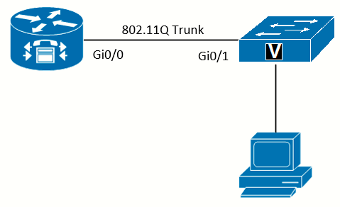 Topology
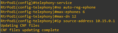
Task 2: Configure Telephony-Service
Telephony-service is where settings that impact the entire CUCME system are configured.
Configure Required Telephony-Service Settings
If necessary, consult Lab 5-1 for more detail on the individual commands.
On older versions of CUCME, it might be necessary to create the template files manually using the create cnf-files command in the telephony-service config mode.
Configure System Time in Telephony Service
Even with the router's clock showing the correct local time, some phone models will not display the correct time. The time-zone command in telephony-service can fix this.
Not required if using Cisco Unified IP Phone models 7902G, 7905G, 7912G, 7920, 7921, 7935, 7936, 7940, 7960, or 7985G).
For Spain in summer time:
RtrPod1(config-telephony)#time-zone ?
  <1-53>  select timezone name used by IP phones (offset in minutes)
<output ommited>
20 Azores Standard/Daylight Time -60
21 GMT Standard/Daylight Time +0
22 Greenwich Standard Time +0
23 W. Europe Standard/Daylight Time +60
24 GTB Standard/Daylight Time +60
25 Egypt Standard/Daylight Time +60
26 E. Europe Standard/Daylight Time +60
27 Romance Standard/Daylight Time +120
28 Central Europe Standard/Daylight Time +120
29 South Africa Standard Time +120
<output ommited>

RtrPod1(config-telephony)#time-zone 27 ?
Configure a Banner Message for Phones with a Display
There are a variety of items on the phone display that can be customized:
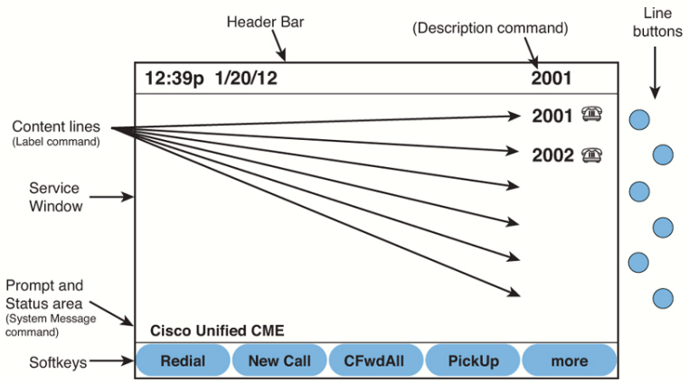 Cisco Unified IP Phone Display
Having all phones with a display prompt showing the default “Cisco Unified CME” message might not be what you want. Use the system message command to change the prompt.
RtrPod1(config-telephony)#system message Jimenez Research IncorporatedTask 3: Configure Ephone-DNs
As noted in Lab 5-1, ephone-dns can be single-line, dual-line and octo-line. Most phones will use dual-line option.
Add the name Option to an Ephone-DN
After the extension is assigned to an ephone-dn, other options can be assigned. One of the most common is the name command. This not only shows the display for incoming and outgoing calls, but it also builds the directory that can be used on the phone.
RtrPod1(config)#ephone-dn 1 dual-line
RtrPod1(config-ephone-dn)#
Jul 1 23:02:53.967: %LINK-3-UPDOWN: Interface ephone_dsp DN 1.1, changed state to up
Jul 1 23:02:53.967: %LINK-3-UPDOWN: Interface ephone_dsp DN 1.2, changed state to up
RtrPod1(config-ephone-dn)#number 5000
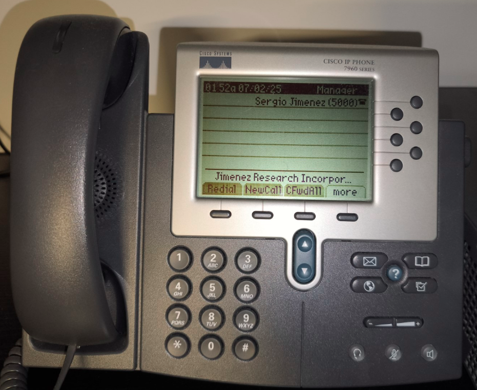
RtrPod1(config-ephone-dn)#name Sergio JimenezChange the Phone Display Header Bar
At the top of the phone display is the header bar. On the left is the time and date, and on the right is the text that shows the extension number on button 1. Use the description command on the ephone-dn assigned to button 1 to change the text to whatever you
want. The user's name, the full E.164 number, and the phone description are examples of information that might be displayed in the header bar.
RtrPod1(config-ephone-dn)#description ManagerThe description only shows on the display if the ephone-dn is attached to button 1 on a phone.
Change the Text for Each Line Button
As shown in Lab 5-1, the extension number displays next to each line button. There are reasons you might want to change this to be more descriptive. The label command will replace the extension with the text specified. Examples include adding the extension user’s name, intercom descriptions, and so on. The label will show on every line button text the ephone-dn is assigned to.
Because the label command replaces the extension, it might be good practice to include the extension in parentheses at the end of the label. While it is helpful to see the name or purpose of the extension, most people like to also see the extension number in question so that they know the number to dial. Understand that the label only impacts the display on the phone; it does not impact caller ID or the directory information.
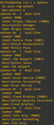
RtrPod1(config-ephone-dn)#label Sergio Jimenez (5000)Create the Other Ephone-DNs
Repeat the steps shows for the other five ephone-dns, using the next five extension numbers according to the addressing scheme:
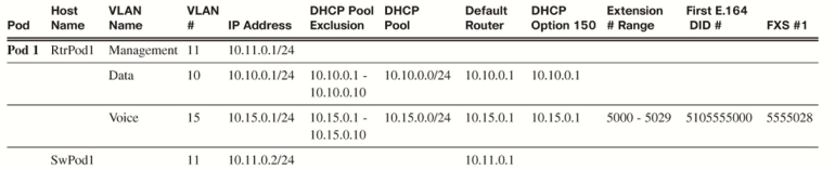
Assign names, descriptions, and labels of your choice for each extension:
Task 4: Configure Ephones
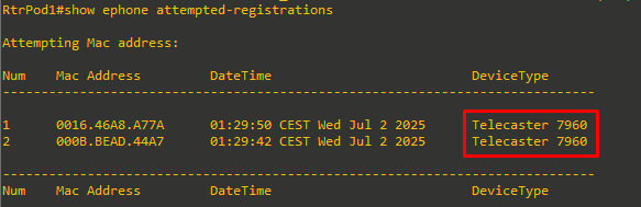
Create an Ephone, and Assign the MAC Address and a Directory Number
With the no auto-reg-ephone option set in telephony-service (see Lab 5-1), you can connect the phones to the switch. (If they are all the same model, you might want to connect and register them one at a time.) Use the show ephone attempted-registrations command to collect the MAC addresses:
RtrPod1(config)#ephone 1
RtrPod1(config-ephone)#mac-address 0016.46A8.A77A
RtrPod1(config-ephone)#button 1:1
As noted in Lab 5-1, there are other options for the button separator than the colon (:):
- f (feature ring): This produces a “stutter” triple ring. This is useful to distinguish the ring when more than one button is assigned to the phone. For example, a feature ring can be used to easily distinguish whether a caller to your phone is on your line or a coworker’s extension on another line button.
- s (silent ring): This allows you to answer or use a line without having it ring.
- m (monitor line): This allow you to monitor the status of an extension, and the button can be used to transfer a call to the
extension.
Assign the Ephone Model Type
For the router to properly recognize the features on each type of phone, it is necessary to tag each ephone with the model. For example, the directory on the phone will not work without a phone type assigned. Handily, the show ephone attempted-registrations command will display the model as well as the MAC address. Note: The Cisco IP Communicator uses the type CIPC for the command:
RtrPod1(config-ephone)#type 7960Assign Users to the Phones
For users to log in to the system (for example, to manage their own settings), they need a username and password. Additionally, when using the phone keypad, some features require a PIN. Both of these items are assigned to an ephone:
RtrPod1(config-ephone)#username sjimenez password cisco
RtrPod1(config-ephone)#pin 1234
Create the Other Ephones
Since I currently have just another phone connected, I will repeat the steps just for this phone and assign it the second user:
RtrPod1(config)#ephone 2
RtrPod1(config-ephone)#mac-address 000B.BEAD.44A7
RtrPod1(config-ephone)#button 1:2
RtrPod1(config-ephone)#type 7960
RtrPod1(config-ephone)#username mpoza password cisco
RtrPod1(config-ephone)#pin 1234
Task 5: Test and Save Configuration
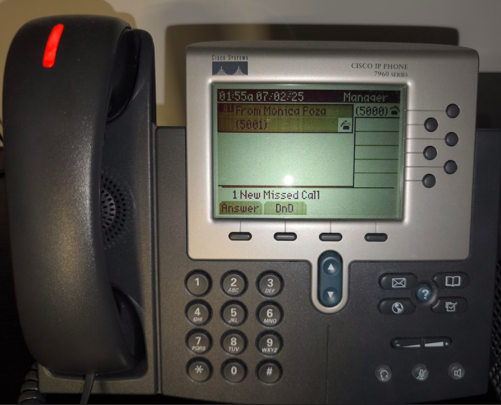
After the phones register, you should immediately notice the differences on the display. Make some calls and observe that the display now shows the name of the calling/called person in addition to the extension. Now you can see the name of the person calling you and not just the extension.
|
|
|