Lab 3-1: Network Connectivity
In both CUCME and CUCM environments, phones need to connect to the network to receive services such as IP addresses from DHCP, VLAN assignments for voice traffic, IP information on where to register, and NTP packets. This lab focuses on establishing those services.
Equipment Required
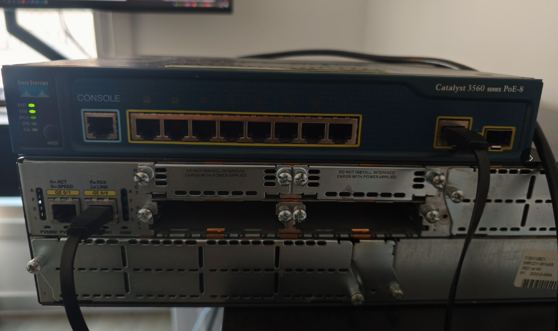
- Cisco 2821 router
- Cisco 3560 switch
- PC for testing
- Cisco IP Phone
Objectives
- Perform basic router and switch configuration.
- Configure VLANs to support data, voice, and network management traffic.
- Configure VLAN trunking between a router and a switch using subinterfaces.
- Configure router-based DHCP pools for voice and data devices.
Scenario
A company named Jimenez Research Incorporated (JRI) would like to establish its new data network with the expectation of using VoIP in the near future. Before phones are connected, network connectivity must be established and needed services configured.
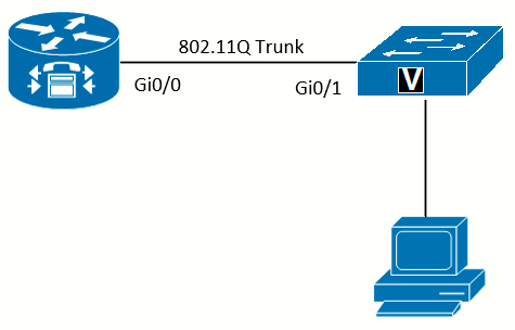
Task 1: Clear and Cable Devices
|
|
 |
|
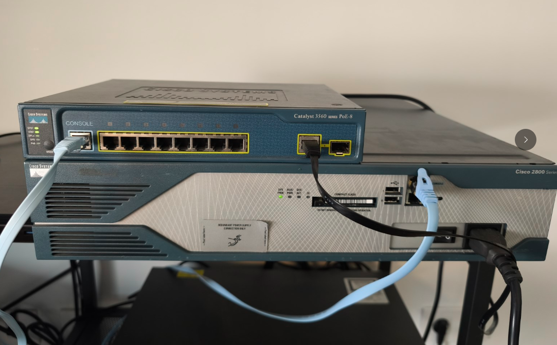
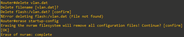
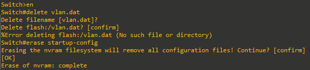
Once connected as per the topology above, next step is to clear configuration on the 2821 and the 3560, delete the vlan.dat before reloading both devices.
Task 2: Configure Basic Setup
We will be using the following addressing schemes and naming conventions:
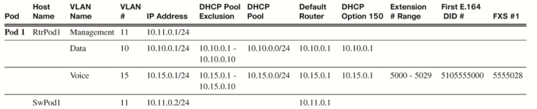
The router and switch basic configuration are as follows
Router(config)# hostname RtrPod1
RtrPodx(config)# enable secret class
RtrPodx(config)# line con 0
RtrPodx(config-line)# logging synchronous
RtrPodx(config-line)# exec-timeout 120 0
RtrPodx(config-line)# password cisco
RtrPodx(config-line)# login
RtrPodx(config-line)# line vty 0 15
RtrPodx(config-line)# password cisco
RtrPodx(config-line)# login
RtrPodx(config-line)# exit
Switch(config)# hostname SwPod1
SwPodx(config)# enable secret class
SwPodx(config)# line con 0
SwPodx(config-line)# logging synchronous
SwPodx(config-line)# exec-timeout 120 0
SwPodx(config-line)# password cisco
SwPodx(config-line)# login
SwPodx(config-line)# line vty 0 15
SwPodx(config-line)# password cisco
SwPodx(config-line)# login
SwPodx(config-line)# exitTask 3: Configure the Switch
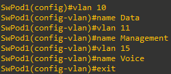
Create the VLANs
For the purposes of security and ease of implementing QoS, use VLANs to keep voice traffic separate from other traffic.
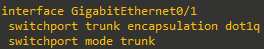
Configure the Trunk Port
After creating the VLANs next step is to configure the trunk port to the router. L3 switches (such as the 3560 I am using) require that the trunking protocol be specified with the switchport trunk encapsulation command before the interface can be set as a trunk (this is not need for pure L2 switches).
Cisco recommends in the “VLAN Security White Paper,” to prevent a double-encapsulated 802.1Q/nested VLAN attack, “always pick an unused VLAN as the native VLAN of all the trunks; don’t use this VLAN for any other purpose. Protocols like STP, DTP, and UDLD should be the only rightful users of the native VLAN and their traffic should be completely isolated from any data packets.” For this reason, the management VLAN is not the native VLAN in this lab. To improve security, it would be better to create another VLAN as the native VLAN that will remain unused, but to simplify this lab, it is not covered.
Configure the Access Ports
Almost all Cisco IP Phones are designed with a three-port switch built inside (one physical port connected to the production switch, one
physical port for a PC to connect to the phone, and one internal port for the phone itself). This built-in switch saves money in wiring costs, as existing phone cabling might not meet networking standards. This enables an existing computer to be plugged into the phone, and the phone connects to the switch in the wiring closet.
Prior to the introduction of voice VLANs, a trunk connected an IP Phone to the switch to keep the voice and data traffic separate. Current best practice configures the ports connected to phones and PCs to use access mode but adds a secondary voice VLAN. The switch ports use the access VLAN to send data traffic as untagged frames. However, if the switch detects a Cisco IP Phone using Cisco Discovery Protocol (CDP), it will inform the phone of the VLAN used for voice traffic, which will be tagged using 802.1q. This creates a pseudotrunk that allows only the data and voice VLANs on the link.
If CDP is disabled, or if using a non-Cisco IP Phone, it requires setting the voice VLAN manually on the IP phone; otherwise the voice traffic will end up on the data VLAN. For this reason, it is recommended that CDP remains enabled for the ports that might have Cisco IP Phones connected.
I am using a 8-port 3560 (WS-C3560-8PC) so the 8 FastEthernet ports will be configured as follows:
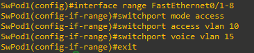
Setting the voice VLAN automatically enables spanning-tree portfast, so the switch port does not have to wait for STP and goes active right away.
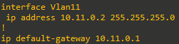
Configure the Switch Management Interface (SVI)
To manage the switch remotely:
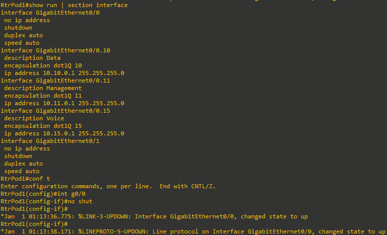
Task 4: Configure the Router Subinterfaces
Subinterfaces allow the VLANs to cross a trunk link to the router (router-on-a-stick). Each subinterface will be the default gateway for a paired subnet. When using subinterfaces on a router, it is necessary to assign the correct VLAN to the subinterface before an IP address can be entered. Because there are three VLANs, you need three subinterfaces.
After configuring them as follows I will need to no shut the parent interface:
Task 5: Verification
SwPod1#sh vlan

VLAN Name                             Status    Ports
---- -------------------------------- --------- -------------------------------
1    default                          active
10   Data                             active    Fa0/1, Fa0/2, Fa0/3, Fa0/4
                                                Fa0/5, Fa0/6, Fa0/7, Fa0/8
11   Management                       active
15   Voice                            active    Fa0/1, Fa0/2, Fa0/3, Fa0/4
                                                Fa0/5, Fa0/6, Fa0/7, Fa0/8
<output ommited>
SwPod1#show interfaces switchport
Name: Gi0/1
Switchport: Enabled
Administrative Mode: trunk
Operational Mode: trunk
Administrative Trunking Encapsulation: dot1q
Operational Trunking Encapsulation: dot1q
Negotiation of Trunking: On
Access Mode VLAN: 1 (default)
Trunking Native Mode VLAN: 1 (default)
Administrative Native VLAN tagging: enabled
Voice VLAN: none
Name: Fa0/1
Switchport: Enabled
Administrative Mode: static access
Operational Mode: down
Administrative Trunking Encapsulation: negotiate
Negotiation of Trunking: Off
Access Mode VLAN: 10 (Data)
Trunking Native Mode VLAN: 1 (default)
Administrative Native VLAN tagging: enabled
Voice VLAN: 15 (Voice)
<output ommited>RtrPod1#show ip interface brief
Interface IP-Address OK? Method Status Protocol
GigabitEthernet0/0 unassigned YES NVRAM up up
GigabitEthernet0/0.10 10.10.0.1 YES manual up up
GigabitEthernet0/0.11 10.11.0.1 YES manual up up
GigabitEthernet0/0.15 10.15.0.1 YES manual up up
GigabitEthernet0/1 unassigned YES NVRAM administratively down downTask 6: DHCP Services
The DHCP option 150 tells Cisco IP Phones the IP address of the TFTP server with the initial configuration file. When using CUCME, the router is the TFTP server by default. This lab assigns the default gateway IP address as the option 150 address, as there is only one way to reach the call agent in this network.
If there was redundancy in the network, it would be worthwhile to create a loopback interface and set the option 150 address to the loopback address, as that interface is always up.
Always enter the ip dhcp exclude address command before a DHCP pool is created. This avoids IP addresses that should be excluded from being assigned to devices. Enter the network statement as the last command in the pool. Otherwise, if devices are connected, they are assigned an IP address by DHCP right after the network statement is entered, even if the default gateway and option 150 are not configured. This can make troubleshooting difficult, as the PCs and phones will receive IP addresses, but the phones will not register and the PCs will not communicate outside their own subnet without the default router (gateway) address.
Create DHCP pools for both the data and voice networks. While it might seem that option 150 is irrelevant in data VLANs, with software on a PC able to emulate a phone (such as the Cisco IP Communicator software), it makes sense to include it for both DHCP pools.
RtrPod1#show run | section ip dhcp
ip dhcp excluded-address 10.10.0.1 10.10.0.10
ip dhcp excluded-address 10.15.0.1 10.15.0.10
ip dhcp pool Data
   network 10.10.0.0 255.255.255.0
   default-router 10.10.0.1
   option 150 ip 10.10.0.1
ip dhcp pool Voice
   network 10.15.0.0 255.255.255.0
   default-router 10.15.0.1
   option 150 ip 10.15.0.1
Task 7: Test and Cleanup
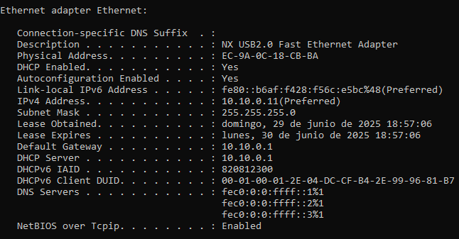
I will connect a PC to the switch using an USB-to-Ethernet adapter and verify if it is given an IP address from the 10.10.0.0/24 subnet:
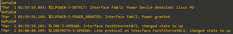
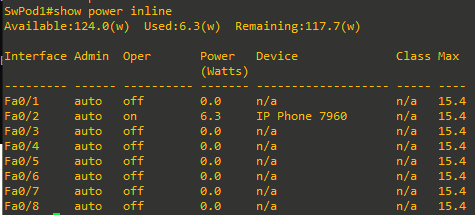
Optional: PoE Verification
At this moment a 7960 Phone can be connected to one of the switch ports, and we can get some output from the show power inline command: