
Appendix E: PSTN Simulator
Introduction
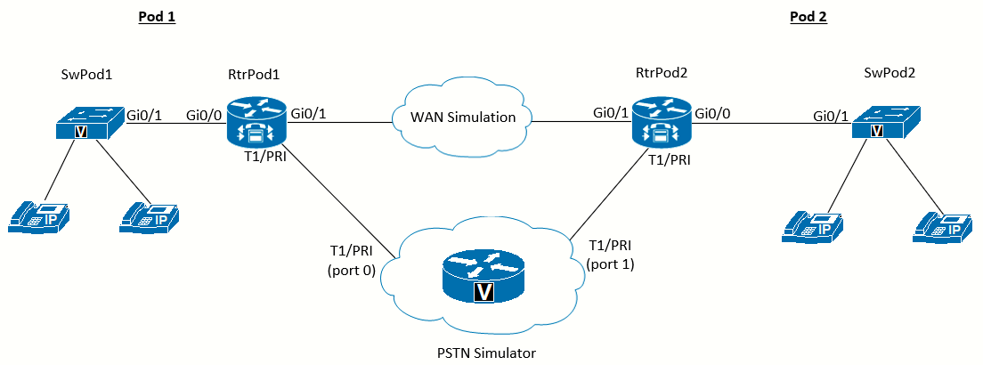
The PSTN Simulator is a Cisco router (a Cisco 2821 in this lab) with one or more T1/E1/PRI interfaces (and enough digital signal processor [DSP] resources to run the interfaces), configured to respond to incoming calls and to forward calls for other pods to the correct interface. The PSTN Simulator plays a unique audio file when any of the categories of phone numbers shown in the following table are sent to the Simulator:
| Call Category | Response |
|---|---|
| Emergency (112) | Play emergency.au file |
| Mobile (6xx and 7xx) | Play mobile.au file |
| Geographic Landlines | Play landline.au file |
| Pod-to-pod | Send call to the interface assigned to the pod |
TCL and .au files
The audio response is achieved by using the Tool Command Language (TCL) scripts paired with an audio file encoded as .au for each call category. To create the audio file, I have used a text-to-speech tool were I generated a distinctive speech for each category (in Spanish, "Servicios de emergencia" for the 112, "Llamada a móviles" for the mobile numbers, and "Llamada a fijos" for the landline numbers).
The tool generates the files in .mp3 but we need it to convert it to "Cisco" format (The file should be in G.711 format. The file can be in .au or .wav file format, but the file format must contain 8-bit 8-kHz data; for example, ITU-T A-law or mu-law data format).
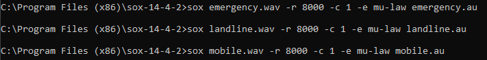
So, I will use the tool SoX to convert them to an appropriate format, using the command sox <input_file>.mp3 -r 8000 -c 1 -e mu-law <output_file>.au
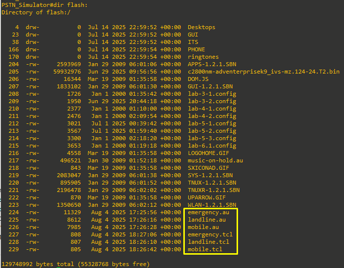
Once the files are generated I will copy them to the PSTN_Simulator router flash.
Now, for each call category, there are two files, an audio file and the matching TCL script. A separate TCL file is needed for each audio file to be played.
The TCL script is as follows, just substitute <file>.au with the correct .au file name.
proc init { } {
	global param
	set param(interruptPrompt) true
	set param(abortKey) *
	set param(terminationKey) #
}

proc act_Setup { } {
	global dest
	leg setupack leg_incoming
	leg proceeding leg_incoming
	media play leg_incoming flash:<file>.au
	fsm setstate CALLDISCONNECTED
}

proc act_Cleanup { } {
	call close
}

init
set callfsm(CALL_INIT,ev_setup_indication) "act_Setup,CALLDISCONNECTED"
set callfsm(CALLDISCONECCTED,ev_disconnected) "act_Cleanup,same_state"
set callfsm(CALLDISCONNECTED,ev_disconnected) "act_Cleanup,same_state"
set callfsm(CALLDISCONNECTED,ev_media_done) "act_Cleanup,same_state"
set callfsm(CALLDISCONNECTED,ev_disconnect_done) "act_Cleanup,same_state"
set callfsm(CALLDISCONNECTED,ev_leg_timer) "act_Cleanup,same_state
fsm define callfsm CALL_INIT
The only difference between the TCL files is the audio file that is referenced. So, in our case we should have:
| AUDIO FILE | MATCHING TCL SCRIPT |
| emergency.au | emergency.tcl |
| mobile.au | mobile.tcl |
| landline.au | landline.tcl |
The name of the audio file and the reference in the TCL script are case sensitive and must match.
Use in Lab 6-2 (link to lab)
The PSTN_Simulator router itself will have an VWIC2-2MFT-T1/E1 card installed. This provides 2-Port RJ-48 Multiflex Trunk - T1/E1.
The PSTN_Simulator is first used in Lab 6-2, where it can work with just the following configuration:
hostname PSTN_Simulator

! The card type command is needed if Multiflex T1/E1 cards are installed (see the
note in lab 6-2, step 2-1 for details). In this case the network module, and the
VWIC2-1MFT-T1/E1 card installed in it, need to choose T1 or E1.

card type t1 0 0

! The network-clock-participate command is needed for the PRI configuration for each
network module and VWIC (see lab 6-2, step 3-2 for details).

network-clock-participate wic 0

! The isdn switch-type command is needed for the PRI configuration (see lab 6-2, step
3-1 for details).

isdn switch-type primary-ni

! The controller interface names will depend on the VWICs and network modules
installed (adjust as necessary). This configuration has a single VWIC2-2MFT-T1/E1 card, there is only one connection, to RtrPod1. The timeslots are configured to support 4 PRI channels for each interface (which might be limited by your PVDM resources) (see lab 6-2, step 3-4 for details).

controller T1 0/0/0
description Connection_To_RtrPod1
framing esf
linecode b8zs
pri-group timeslots 1-4

! Each of the controllers has a matching serial interface (see lab 6-2 for details)
Note that the isdn protocol-emulate network command is what makes this the provider
end of the circuit.

interface Serial0/0/0:23
description Pod 1
no ip address
isdn switch-type primary-ni
isdn protocol-emulate network
isdn incoming-voice voice
no cdp enable
Please beware, the configuration above:
- Assumes port Serial0/0/0:23 for the matching serial interface.
- Assumes T1 port 0/0/0
- Note that the isdn protocol-emulate network command is what makes this router the provider end of the circuit.
On this lab, the PSTN_Simulator router is just used to test the T1 connection to RtrPod1.
Use in Lab 6-5 (link to lab)
The card VWIC2-2MFT-T1/E1 card has exactly 2 ports. I will make use of both of them for Lab 6-5, with port 0/0/0 connecting to RtrPod1 and port 0/0/1 connecting to RtrPod2. We want to wire the router as follows:
For this lab we must further configure the PSTN_Simulator (adding to the configuration for Lab 6-2), as follows:
! The controller interface names will depend on the VWICs and network modules installed (adjust as necessary).

controller T1 0/0/1
 pri-group timeslots 1-4,24
 description Connection_To_RtrPod2

! Each of the controllers has a matching serial interface (see lab 6-2 for details) Note that the isdn protocol-emulate network command is what makes this the provider
end of the circuit

interface Serial0/0/1:23
 description Pod 2
 no ip address
 isdn switch-type primary-ni
 isdn protocol-emulate network
 isdn incoming-voice voice
 no cdp enable

! This application is used to call the emergency number (112) TCL script

application
service emergency flash:emergency.tcl
exit

! This application is used to call the mobile numbers TCL script

application
service mobile flash:mobile.tcl
exit

! This application is used to call the landline numbers TCL script

application
service landline flash:landline.tcl
exit

! Dial-peers for Spain emergency, mobile and landline numbers

dial-peer voice 112 pots
description Spain - Emergency
service emergency
incoming called-number 112

dial-peer voice 1 pots
description Spain - Mobile (6)
service mobile
incoming called-number 6........

dial-peer voice 2 pots
description Spain - Mobile (7)
service mobile
incoming called-number 7[1-4].......

dial-peer voice 3 pots
description Spain - Landline
service landline
incoming called-number [89][1-8].......

! Dial-peers 101 and 102 direct dialed numbers in the range of the pods to the correct interface. Read the descriptions in each dial-peer to see which pod is configured.

dial-peer voice 101 pots
description Calls to Pod 1
destination-pattern 51055550[0-2].
port 0/0/0:23
prefix 51055550

dial-peer voice 102 pots
description Calls to Pod 2
destination-pattern 51055550[3-5].
port 0/0/1:23
prefix 51055550

! Dial-peer 123 directs the router to use direct-inward-dial for incoming calls (see
lab 6-5, step 5-1 for details).

dial-peer voice 123 pots
incoming called-number .
direct-inward-dial
Additional to this configuration, it will be useful to explore digit manipulation using voice translation profiles, which will be needed for Lab 6-5 Task 7. We will need to add the following configuration before starting that task:
! The voice translation-rule converts the received 7-digit from each pod to the 10-digit version. We are matching on translation-rule 1 the number range for Pod 1 and on translation-rule 2 the number range for Pod 2.

voice translation-rule 1
 rule 1 /^\(55550[0-2][0-9]\)$/ /510\1/

voice translation-rule 2
 rule 1 /^\(55550[3-5][0-9]\)$/ /510\1/

! We are creating translation-profiles to apply the translation-rules and saying "hey, translate this received number to be called as this (as the set statement on the translation-rule)"

voice translation-profile Outgoing_To_Pod1
 translate called 1
!
voice translation-profile Outgoing_To_Pod2
 translate called 2

! The logic to apply the translation profiles on the voice ports is as follows. On the T1 connected to Pod 1 we are saying "translate the incoming called numbers applying translation-rule 2". This way it matches the called numbers to Pod 2 (i.e 5555030) and translates it to 5105555030, so it can match dial-peer 102. The same logic is applied to the other voice-port.

voice-port 0/0/0:23
 translation-profile incoming Outgoing_To_Pod2

voice-port 0/0/1:23
 translation-profile incoming Outgoing_To_Pod1
More info on the translation rules logic can be found here: Determine Voice Translation Rules
Following is an output after debug voice translation and debug voip dialpeer have been enabled:
PSTN_Simulator#
//-1/xxxxxxxxxxxx/RXRULE/regxrule_get_profile_from_voiceport_internal: Found profile Outgoing_To_Pod2
  defined on voice-port
//-1/xxxxxxxxxxxx/RXRULE/regxrule_profile_match_internal: Matched with rule 1 in ruleset 2
//-1/xxxxxxxxxxxx/RXRULE/sed_subst: Successful substitution; pattern=5555030 matchPattern=^(55550[3-5][0-9])$ replacePattern=510\1 replaced pattern=5105555030
//-1/xxxxxxxxxxxx/RXRULE/regxrule_subst_num_type: Match Type = none, Replace Type = none Input Type = subscriber
//-1/xxxxxxxxxxxx/RXRULE/regxrule_subst_num_plan: Match Plan = none, Replace Plan = none Input Plan = isdn
//-1/xxxxxxxxxxxx/DPM/dpAssociateIncomingPeerCore:
   Calling Number=5105555000, Called Number=5105555030, Voice-Interface=0x49B9FBEC,
   Timeout=TRUE, Peer Encap Type=ENCAP_VOICE, Peer Search Type=PEER_TYPE_VOICE,
   Peer Info Type=DIALPEER_INFO_SPEECH
//-1/xxxxxxxxxxxx/DPM/dpAssociateIncomingPeerCore:
   Result=Success(0) after DP_MATCH_INCOMING_DNIS; Incoming Dial-peer=123
//-1/xxxxxxxxxxxx/DPM/dpAssociateIncomingPeerCore:
   Calling Number=5105555000, Called Number=5105555030, Voice-Interface=0x0,
   Timeout=TRUE, Peer Encap Type=ENCAP_VOICE, Peer Search Type=PEER_TYPE_VOICE,
   Peer Info Type=DIALPEER_INFO_FAX
//-1/xxxxxxxxxxxx/DPM/dpMatchPeersCore:
   Calling Number=, Called Number=5105555030, Peer Info Type=DIALPEER_INFO_SPEECH
//-1/xxxxxxxxxxxx/DPM/dpMatchPeersCore:
   Match Rule=DP_MATCH_DEST; Called Number=5105555030
//-1/xxxxxxxxxxxx/DPM/dpMatchPeersCore:
   Result=Success(0) after DP_MATCH_DEST
//-1/xxxxxxxxxxxx/DPM/dpMatchPeers:
   Result=SUCCESS(0)
   List of Matched Outgoing Dial-peer(s):
     1: Dial-peer Tag=102
References
RJ48C, RJ48S, RJ48X - T1 Jacks - Cable
https://www.arcelect.com/RJ48C_and_RJ48S_8_position_jack_.htm