
Lab 5-1: Basic Manual Phone Configuration Using the CLI
With previous labs building the foundation for telephony concepts and a network topology, it is time to turn our attention to configuring the Call Agent. In the following labs we will learn to configure Cisco Unified Communications Manager Express (CUCME) using both the CLI and CCP.
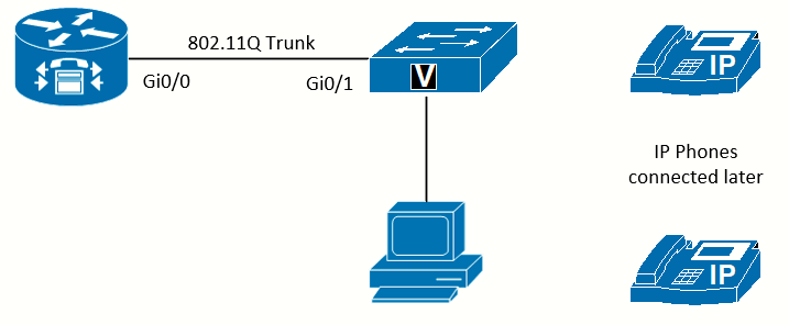 Topology used in this lab
Equipment Required
- Cisco 2821 router
- Cisco 3560 switch
- Lab configuration from either Lab 3-1 or Lab 3-2
- Two or more IP Phones
Objectives
- Configure telephony services in CUCME
- Manually register phones
- Place phone calls between two phones in the same system
Scenario
Jimenez Research Inc. (JRI) wants to establish internal calls using the new system.
Task 1: Load Prior Configurations
This lab is based on the configuration from Lab 3-2. If necessary, load the configuration for both switch and router, and cable the devices as the topology shown on Lab 3-2:
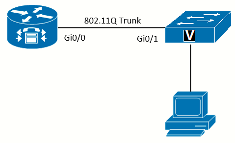 Topology
Task 2: Configure Telephony-Service
Telephony-service configuration mode is where settings that impact the entire CUCME system are configured. There are three settings that must be configured before phones can register, and one optional setting that avoids common phone registration mistakes.
Disable Auto Phone Registration
Disabling autoregistration of phones is an optional step. However, allowing phones to autoregister can cause problems if MAC addresses are entered incorrectly. Disabling autoregistration eliminates this problem.
RtrPod1(config)#telephony-service
RtrPod1(config-telephony)#no auto-reg-ephone
Establish the Maximum Number of Phones Allowed to Register
Before any IP phones can register with the system, the maximum number allowed to register must be set. The upper limit is dependent on the model of the router; the higher the model number, the more IP Phones CUCME will support. While it might seem best to set the number to the maximum a given router will support, each reservation consumes resources on the router; thus it is better to set the number as slightly above the currently expected number of phones. It can be increased later (up to the maximum supported by the router model) without disrupting operations.
The maximum should also be set no higher than the number of licenses purchased.
The maximum number of ephones on the 2821 is 58:
RtrPod1(config-telephony)#max-ephones ?
  <1-58>  Maximum phones to support

RtrPod1(config-telephony)#max-ephones 5
RtrPod1(config-telephony)#
Establish the Maximum Number of Directory Numbers (Phone Numbers)
Before any phones can register with the system, the maximum number of directory numbers must also be set. The upper limit of the maximum is dependent on the model of the router, but it will be higher than the number of phones. If you consider that DN will be used for intercoms, paging, voicemail numbers, and so on, you can see why there are more numbers allocated than phones. Again, each DN will consume resources on the router; thus it is better to set the number at slightly above the current expected number of directory numebrs needed. As with the phones, it can always be increased later (up to the maximum supported by the router model) without disrupting operations.
The maximum DNs on the 2821 is 192:
RtrPod1(config-telephony)#max-dn ?
  <1-192>  Maximum directory numbers supported

RtrPod1(config-telephony)#max-dn 10
RtrPod1(config-telephony)#
Set the IP Address Used by CUCME
Before any phones can register with the system, CUCME needs to know the IP address used to receive requests and respond to IP Phones. The ip source-address command tells the system the IP address to use. By default, TCP port 2000 is used, but it can be specified with the port option. Any valid IP address on the router can be used, but the address of the voice VLAN interface is the best choice in this case.
The best option for the source address is a loopback address, as loopback interfaces are always up. Using a physical interface (or
subinterface) address could cause the system to stop responding if that interface is down, even if phones are connected to other
interfaces that are up. However, in this configuration, if the interface is down, all phones are disconnected, so a loopback is not
necessary.
NTP should be properly configured before the execution of this command.
RtrPodx(config-telephony)# ip source-address 10.15.0.1Allow the Router to Send TFTP Files from Flash
As part of the basic security for each router, it does not respond to TFTP requests for files. Because you are telling the phones in Lab 3-1 to use the router as the TFTP server, you need to allow the router to respond to the firmware requests. The tftp-server command enables the router to send the specified file using TFTP (which normally would be blocked). Do not forget that some phone models are identical, except for the number of buttons on the phone, so they use the same firmware. Thus, when looking at the phone firmware files, both a 7942 and a 7962 phone use almost the same files (there is one file that is unique for each model that influences the buttons allowed on each).
If directories to store the phone files were used (like I did, creating the phone folder under flash:) an additional parameter will be needed. Because the phone does not know about my folder structure on the router, it just requests the files it needs, but those files are not in the root directory. The alias command (like a shortcut) allows the file to be redirected to the actual location on the flash where the file is stored:
flash:/phone/P00308000500.loads
flash:/phone/P00308000500.sb2
flash:/phone/P00308000500.sbn

RtrPod1(config)#$ tftp-server flash:/phone/P00308000500.loads alias P00308000500.loads
RtrPod1(config)#$ tftp-server flash:/phone/P00308000500.sbn alias P00308000500.sbn
RtrPod1(config)#$ tftp-server flash:/phone/P00308000500.sb2 alias P00308000500.sb2
Inform the Phone of the Updated Firmware to Load
After the files are loaded on the router and the router is configured to send the files using TFTP, the phone needs to be told what version of firmware to load. In telephony service, the load command does this. After the load command is issued with the correct protocol firmware file, the cnf files need to be re-created and the phone reset to discover the new firmware files:
RtrPod1(config)# telephony-service
RtrPod1(config-telephony)# load 7960-7940 P00308000500
RtrPod1(config-telephony)#no create cnf-files
CNF files deleted

RtrPod1(config-telephony)#create cnf-files
Creating CNF files
If the phone was already connected to the switch it should be factory reset. To do this on the 7960G follow this procedure:
-
Unplug the power cable from the phone, and then plug in the cable again. The phone begins its power up cycle.
- Immediately press and hold # and while the Headset, Mute, and Speaker buttons begin to flash in sequence, release #.
- The Headset, Mute, and Speaker buttons flash in sequence in order to indicate that the phone waits for you to enter the key sequence for the reset.
- Press 123456789*0# within 60 seconds after the Headset, Mute, and Speaker buttons begin to flash.
-
If you enter this key sequence correctly, the phone displays this prompt:
Keep network cfg? 1 = yes 2 = no
- In order to reset the network configuration settings when the phone resets, press 2. The phone goes through the factory reset process
After this, if we enable the debug tftp events we can see how the phone asks and gets the firmware files from the CUCME router:
RtrPod1#debug tftp events
TFTP Event debugging is on
Jun 29 22:38:10.413: TFTP: Looking for CTLSEP001646A8A77A.tlv
Jun 29 22:38:10.433: TFTP: Looking for SEP001646A8A77A.cnf.xml
Jun 29 22:38:10.453: TFTP: Looking for SIP001646A8A77A.cnf
Jun 29 22:38:10.485: TFTP: Looking for MGC001646A8A77A.cnf
Jun 29 22:38:10.505: TFTP: Looking for XMLDefault.cnf.xml
Jun 29 22:38:10.505: TFTP: Opened system:/its/vrf1/XMLDefault.cnf.xml, fd 7, size 2834 for process 337
Jun 29 22:38:10.513: TFTP: Finished system:/its/vrf1/XMLDefault.cnf.xml, time 00:00:00 for process 337

Jun 29 22:38:10.557: TFTP: Looking for P00308000500.loads
Jun 29 22:38:10.561: TFTP: Opened flash:/phone/P00308000500.loads, fd 7, size 458 for process 337
Jun 29 22:38:10.565: TFTP: Finished flash:/phone/P00308000500.loads, time 00:00:00 for process 337

Jun 29 22:38:12.413: TFTP: Looking for P00308000500.sb2
Jun 29 22:38:12.417: TFTP: Opened flash:/phone/P00308000500.sb2, fd 7, size 705536 for process 337
Jun 29 22:38:14.957: TFTP: Finished flash:/phone/P00308000500.sb2, time 00:00:02 for process 337
Create the Default Template Files
With newer versions of CUCME, the system will automatically create the default template files for the phones after all required options are entered. A message will say:
RtrPod1(config-telephony)#ip source-address 10.15.0.1
Updating CNF files
CNF files updating complete
On older versions, entering the create cnf-files command might be necessary.
Sometimes, if a change is made in the Telephony Services section of the config, and the changes do not show on the phones, using the no create cnf-files and then the create cnf-files commands to manually re-create the template files (followed by restarting the phones) will fix the problem.
Inspect the IP Phone Generic Config File
When phones boot and receive the option 150 address from DHCP, they use that address to contact the TFTP server to get a configuration file. The phone will request an SEP<phone_MAC_address>.cnf.xml file that contains the settings the phone should use, which the TFTP should have if the phone is registered. If the phone is not registered, or if the TFTP server does not have the file, the phone will next request the default config file called XMLDefault.cnf.xml. The router is acting as the TFTP server in this lab; normally the router will not respond to TFTP requests. To see what files the router will hand out, and where they are located, use the show telephony-service tftp-bindings command. The file we are interested in is the XMLDefault.cnf.xml file:
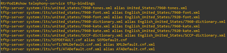
You can view the file right on the router using the more command.
RtrPod1#more system:/its/vrf1/XMLDefault.cnf.xml
<Default>
<callManagerGroup>
<members>
<member  priority="0">
<callManager>
<ports>
<ethernetPhonePort>2000</ethernetPhonePort>
</ports>
<processNodeName>10.15.0.1</processNodeName>
</callManager>
</member>
</members>
</callManagerGroup>
<loadInformation124  model="Cisco IP Phone 7914 14-Button Line Expansion Module"></loadInformation124>
<loadInformation227  model="Cisco IP Phone 7915 12-Button Line Expansion Module"></loadInformation227>
<loadInformation228  model="Cisco IP Phone 7915 24-Button Line Expansion Module"></loadInformation228>
<loadInformation229  model="Cisco IP Phone 7916 12-Button Line Expansion Module"></loadInformation229>
<loadInformation230  model="Cisco IP Phone 7916 24-Button Line Expansion Module"></loadInformation230>
<loadInformation30008  model="Cisco IP Phone 7902"></loadInformation30008>
<loadInformation20000  model="Cisco IP Phone 7905"></loadInformation20000>
<loadInformation369  model="Cisco IP Phone 7906"></loadInformation369>
<loadInformation6  model="Cisco IP Phone 7910"></loadInformation6>
<loadInformation307  model="Cisco IP Phone 7911"></loadInformation307>
<loadInformation30007  model="Cisco IP Phone 7912"></loadInformation30007>
<loadInformation30002  model="Cisco IP Phone 7920"></loadInformation30002>
<loadInformation365  model="Cisco IP Phone 7921"></loadInformation365>
<loadInformation484  model="Cisco IP Phone 7925"></loadInformation484>
<loadInformation348  model="Cisco IP Phone 7931"></loadInformation348>
<loadInformation9  model="Cisco IP Conference Station 7935"></loadInformation9>
<loadInformation30019  model="Cisco IP Phone 7936"></loadInformation30019>
<loadInformation431  model="Cisco IP Conference Station 7937"></loadInformation431>
<loadInformation8  model="Cisco IP Phone 7940"></loadInformation8>
<loadInformation115  model="Cisco IP Phone 7941"></loadInformation115>
<loadInformation309  model="Cisco IP Phone 7941GE"></loadInformation309>
<loadInformation434  model="Cisco IP Phone 7942"></loadInformation434>
<loadInformation435  model="Cisco IP Phone 7945"></loadInformation435>
<loadInformation7  model="Cisco IP Phone 7960"></loadInformation7>
<loadInformation30018  model="Cisco IP Phone 7961"></loadInformation30018>
<loadInformation308  model="Cisco IP Phone 7961GE"></loadInformation308>
<loadInformation404  model="Cisco IP Phone 7962"></loadInformation404>
<loadInformation436  model="Cisco IP Phone 7965"></loadInformation436>
<loadInformation30006  model="Cisco IP Phone 7970"></loadInformation30006>
<loadInformation119  model="Cisco IP Phone 7971"></loadInformation119>
<loadInformation437  model="Cisco IP Phone 7975"></loadInformation437>
<loadInformation302  model="Cisco IP Phone 7985"></loadInformation302>
<loadInformation12  model="ATA  phone emulation for analog phone"></loadInformation12>
</Default>
Task 3: Configuring Directory Numbers
A directory number (phone number) is represented in Cisco configs as an ephone-dn. (Think directory number.) Ephone-dns can be single-line, dual-line, and as of CUCME 4.1, octo-line. The distinction is in the number of simultaneous audio channels (lines) usable per phone button. For example, call waiting and transferring a caller to a third party need two audio channels. (The call transfer needs one channel for the original caller and another to establish the connection to the third party.) For this reason, most desk phones will use dual-line dns. The single-line dn is used for features like intercoms and paging, where dual-lines are not needed. Octo-line dns have eight audio channels per button. You might wonder, “Why not just make them all octo lines?” Each line created consumes resources on the router, so it is best to allocate the correct number of lines to each directory number. Be aware that you cannot later change the number of lines on a dn. To change the number of lines, you have to use the no command to remove the entire dn and then re-create it.
Create Dual-Line Ephone-DN
The ephone-dns are created in global config. mode, and each dn is assigned a tag number. The tag number has to be less than the max-dn configured in telephony service, so usually you start with 1.
RtrPod1(config)#ephone-dn 1 ?
  dual-line  dual-line DN (2 calls per line/button)
  octo-line  octo-line DN (8 calls per line/button)
  <cr>
RtrPod1(config)#ephone-dn 1 dual-line
RtrPod1(config-ephone-dn)#
Jun 29 21:59:14.408: %LINK-3-UPDOWN: Interface ephone_dsp DN 1.1, changed state to up
Jun 29 21:59:14.408: %LINK-3-UPDOWN: Interface ephone_dsp DN 1.2, changed state to up
RtrPod1(config-ephone-dn)#number 5000
RtrPod1(config-ephone-dn)#ephone-dn 2 dual-line
Jun 29 22:01:29.562: %LINK-3-UPDOWN: Interface ephone_dsp DN 2.1, changed state to up
Jun 29 22:01:29.562: %LINK-3-UPDOWN: Interface ephone_dsp DN 2.2, changed state to up
RtrPod1(config-ephone-dn)#number 5001
RtrPod1(config-ephone-dn)#ephone-dn 3 dual-line
Jun 29 22:01:38.102: %LINK-3-UPDOWN: Interface ephone_dsp DN 3.1, changed state to up
Jun 29 22:01:38.102: %LINK-3-UPDOWN: Interface ephone_dsp DN 3.2, changed state to up
RtrPod1(config-ephone-dn)#number 5002
RtrPod1(config-ephone-dn)#ephone-dn 4 dual-line
Jun 29 22:01:49.238: %LINK-3-UPDOWN: Interface ephone_dsp DN 4.1, changed state to up
Jun 29 22:01:49.238: %LINK-3-UPDOWN: Interface ephone_dsp DN 4.2, changed state to up
RtrPod1(config-ephone-dn)#number 5003
If you make an ephone-dn with an incorrect number of lines you have to remove the ephone-dn using the no ephone-dn number command and re-create it.
Task 4: Manually Configure an Ephone and Associate the First Directory Number
In a traditional analog or PBX phone system, a DN (phone number) is associated with a wall jack. Any phone plugged into a wall
jack will have the phone number assigned to that jack. Move the phone to another wall jack and the number on the phone changes (unless the line in the jack is manually changed). However, with IP Phones, the phone is identified by the MAC address assigned to it, so it does not matter where in the network the phone is located. As long as the phone can reach the Call Agent, it will be have the same directory numbers. CUCME uses the ephone to connect directory numbers (ephone-dns) to the MAC address of the phone.
Get the MAC Address of the First Phone
There are three main ways to get the MAC address of a phone:
- From the box of the IP Phone.
- From the back of the IP Phone.
- From the screen of the IP Phone.
The MAC should be formatted in three groups of four hex numbers, separated by periods.
The MAC of my first connected phone is 0016.46A8.A77A
Create an Ephone and Assign the MAC Address
Just like ephone-dns, the ephone requires a tag number that must be less than the max.-ephone number defined in telephony-service. After entering config-ephone mode, the mac-address command is mandatory before any other command can be issued.
RtrPod1(config)#ephone 1
RtrPod1(config-ephone)#mac-address 0016.46A8.A77A
Assign the First Directory Number to the First Button on the Phone
The next step is to associate one of the ephone-dns to the ephone. Most Cisco phone models are capable of having more than one line assigned to them, and they use line buttons on the phone for the caller to select the line to use.
There are many options when assigning an ephone-dn to a button. The most common option is to use the colon (:) to connect the physical button on the phone to the ephone-dn.
RtrPod1(config-ephone)#button ?
  LINE  button-index:dn-index pairs example 1:2 2:5
Configuration line:button with separator feature options:
: normal phone lines
       example    button 1:2 2:5
s silent ring, ringer muted, call waiting beep muted
       example    button 1s2 2s5
b silent ring, ringer muted, call waiting beep not muted
       example    button 1b2 2b5
f feature ring
       example    button 1f2 2f5
       see also 'no dnd feature-ring'
m monitor line, silent ring, call waiting display suppressed
       example    button 1m2 2m5
       see also 'transfer-system full-consult dss'
w watch line (BLF), watch the phone offhook status via the phone's primary
ephone-dn
       example    button 1w2 2w5
o overlay lines, combine multiple lines per physical button
       example    button 1o2,3,4,5
c overlay call-waiting, combine multiple lines per physical button
       example    button 1c2,3,4,5
       see also  'huntstop channel' for ephone-dn dual-line
x expansion/overflow, define additional expansion lines that are
       used when the primary line for an overlay button is
       occupied by an active call
       Expansion works with 'button o' and not with 'button c'
       example    button 4o21,22,23,24,25
                  button 5x4
                  button 6x4
Different separator options may be use for each button
       example    button 1:2 2s5 3b7 4f9 5m22 6w10

RtrPod1(config-ephone)#button 1:1Connect the First Phone to the Switch
If using a physical phone, connect the cable from the SW port to the switch. The phone should go through the bootup process and register with CUCME. On the router, you will see a registration status message:

Manually Configure a Second Phone
In CUCME, there is an easier way to get the MAC addresses and register a few phones, if you have the no auto-reg-ephone command in telephony-service. With autoregistration disabled, you can connect the phone and the phone registration will fail. This allows you to use the show ephone attempted-registrations command to get the information.
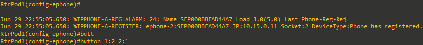
At this point, I connected a second phone to the switch. A message appears on the router console showing a registration alarm. The MAC address is displayed in the output of the alarm, but it is not in the right format. Use the show ephone attempted-registrations command to obtain the MAC address in the right format. In the following example, another Cisco 7960 Phone with MAC address 000B.BEAD.44A7 attempted to register, but there is no matching ephone config.
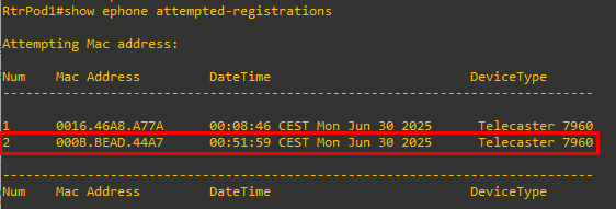
From here, we can copy and paste the MAC address information:
RtrPod1(config)#ephone 2
RtrPod1(config-ephone)#mac-address 000B.BEAD.44A7
Assign the Second and First Directory Numbers to the Second Phone
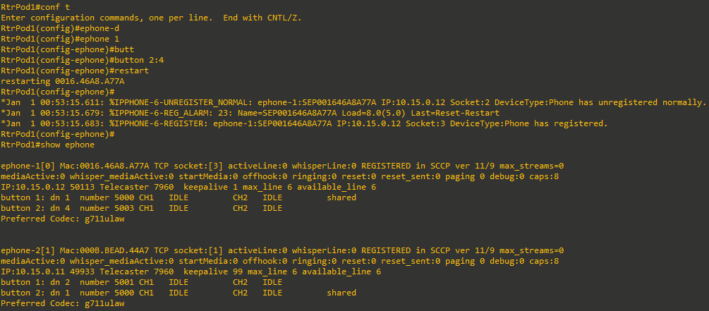
However, you might find that the phone has already registered before you type the button command and it does not show any extensions on the phone display. While in config-ephone mode, you can use either the restart or reset command to update the phone. The phone will unregister and then reregister.
The restart command tells the phone to update the configuration. The reset command tells the phone to completely reboot,
including the full power-up boot process.
Make a Call
Place a call from the first phone (x5000) to the DN assigned on ephone-dn 2 (x5001). When you call from one phone to the other, the display on the ringing phone will show the extension that is called/calling.
Notice that whenever the first phone goes off-hook (x5000), the second line button on the second phone (which was also assigned x5000) changes its symbol to notify the user that the line is being used). This is because both phones share the same ephone-dn assignment. Unlike an analog home phone, where someone can pick up another extension and join the conversation, only one phone can use an ephone-dn at a time.
Assign Other Extensions to the First Phone
Assuming that the first phone has more than one line button, you can assign additional extensions using the button command. You can add additional ephone-dns to unassigned buttons without having to reenter the previous commands. The new assignment is added to the existing configuration.
You can verify the phone status using the show ephone command. In this output, the DN and extensions are assigned to line buttons 1 and 2. Notice there is a channel 1 (CH1) and channel 2 (CH2) status of IDLE for both DNs, as the ephone-dns were created as dual-line and the phone is not in use:
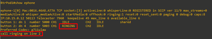
If we place a call from line button 1 on the second phone (x5000) to the extension assigned to button 2 of the first phone (x5003), and then execute the show ephone command again, we get this output:
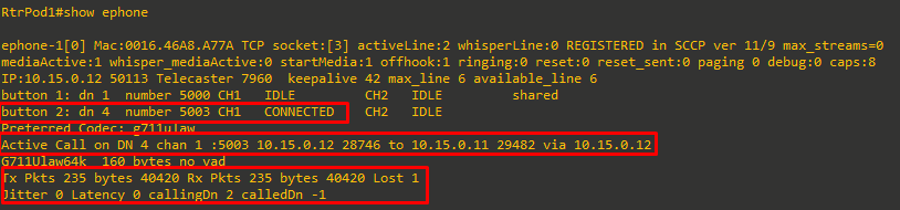
If we answer the call and run the command again. The status now shows the call as CONNECTED and the IP address of both phones. There are also statistics about the packets of the voice conversation:
Sources
Troubleshooting Phone Registration in Cisco Unified CME
https://www.cisco.com/c/en/us/td/docs/voice_ip_comm/cucme/troubleshooting/guide/ts_phreg.html
IOS Licensing
https://networklessons.com/cisco/ccna-routing-switching-icnd1-100-105/ios-licensing