
Lab 6-5: Dial-Peer Configuration Using the CLI
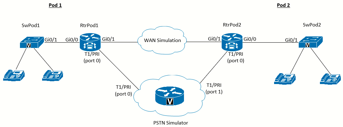 Topology diagram for this lab
Scenario
Jimenez Research Inc. (JRI) wants to connect to customers using the PSTN and remote branch offices of the company using the WAN. To avoid WAN failure from disabling four-digit dialing between locations, call failover from the WAN to the PSTN needs to be configured.
Equipment Required
- Two Cisco 2821 routers with voice IOS (RtrPod1 and RtrPod2).
- Two Cisco 3560 switch (SwPod1 and SwPod2).
- Cisco 2821 router configured as PSTN_Simulator (see Appendix E).
- T1/E1/PRI Multiflex Trunk VWIC cards or Network Modules.
- DSP resources in the routers (PVDM chips) to enable the Multiflex Trunk.
Objectives
- Configure dial peers to connect to the PSTN.
- Configure dial peers to connect to remote offices using the WAN.
- Configure failover for calls to remote offices using the PSTN when the WAN is down.
Task 1: Load Prior Configurations
This lab is based on the configuration from Lab 6-2. If necessary, load the configuration for both the switch and router. Connect a
PC to the switch and verify that it can ping the router and switch management addresses. Connect the VoIP phones and verify that you can call between them. Troubleshoot if necessary.
Also we need RtrPod2 and SwPod2 configured and wired according to the diagram above. The configurations are almost the same as RtrPod1 and SwPod1, just changing the addressing, extensions and names, according to this table:
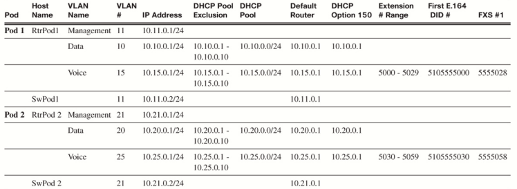
Essentially, the whole lab manual up to this point should be re-done for this new RtrPod2 router and SwPod2 switch but following the above addressing table.
Once we have both pods configured (RtrPod1 / SwPod1, and RtrPod2 / SwPod2) we can continue with the lab.
Task 2: Configure Hardware Used by the Dial Peers
With RtrPod1 and RtrPod2, we need to set up the connection from the PSTN_Simulator to both pods, using PRI crossover cables to connect it to both RtrPod1 and RtrPod2 (refer to the diagram).
Essentially, the following configuration must be added to the PSTN_Simulator, as per Appendix E (the full configuration should be added before the end of Task 4):
controller T1 0/0/1
pri-group timeslots 1-4,24
description Connection_To_RtrPod2
interface Serial0/0/1:23
description Pod 2
no ip address
isdn switch-type primary-ni
isdn protocol-emulate network
isdn incoming-voice voice
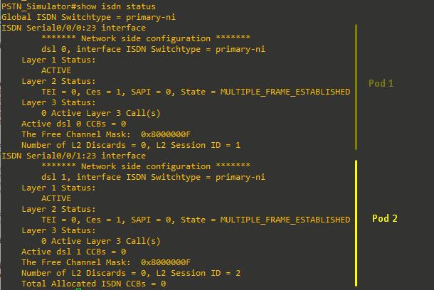
no cdp enableOnce the RtrPod2 T1 interface (0/0/0) is enabled (no shut) we can verify the connections are successfully established between PSTN_Simulator and both pods:
Task 3: Configure Secondary Dial Tone
When configuring a PBX-type dial plan, there needs to be an outside line access digit. Many PBX users are used to hearing a slightly different dial tone after dialing this digit, before dialing the intended PSTN number. This secondary dial tone for outside lines can be configured in telephony-service using the secondary-dialtone command and assuming that 9 will be used as the outside line access digit:
|
|
You will not hear the secondary dial tone until you have at least one working dial peer with a destination pattern that starts with a 9. This command only makes the dial tone change when the first digit is 9. It does not eliminate the need for a 9 in each dial-peer destination pattern that will connect to the PSTN.
Task 4: Configure the PSTN and Pods Dial Peers
Refer to the following document for the dial plan (Spain) to configure the correct dial peers.
For now, we will configure a reduced version of this numbering plan with just the emergency number, mobile and geographic landline numbers:
| Pattern | Number Type | Test Number(s) |
|---|---|---|
| 112 | Emergency | 112 |
|
6........ |
Mobile (beginning with 6) | 612345678 |
| 7[1-4]....... | Mobile (beginning with 7) | 712345678, 790123456 |
| [89][1-8]....... | Geographic landlines (9-digits) | 912345678, 821234567 |
Remember: when a call matches a POTS dial peer, by default the router strips the explicitly matched (nonwildcard) digits on the left.
All the dial peers shown below assume we have a PRI configured in VWIC slot 0 of the router. Number 9 is used as the access digit as per the previous configuration. This digit will be stripped, but we want to make sure in the case of the emergency number and mobile numbers to not strip the leading digit(s). The following dial-peers must be configured on both RtrPod1 and RtrPod2:
Configure Emergency Services Calls
dial-peer voice 112 pots
description Emergency Services
destination-pattern 112
prefix 112
port 0/0/0:23

dial-peer voice 9112 pots
description Emergency Services
destination-pattern 9112
prefix 112
port 0/0/0:23
Configure Mobile Calls
dial-peer voice 1 pots
description Mobile
destination-pattern 96........
prefix 6
port 0/0/0:23

dial-peer voice 2 pots
description Mobile
destination-pattern 97[1-4].......
prefix 7
port 0/0/0:23
Configure Geographic Landline Calls
dial-peer voice 3 pots
description Geographic Landline
destination-pattern 9[89][1-8].......
port 0/0/0:23
Configure Pods Dial Peers
Since we are using just 2 pods for this lab (Pod 1 and Pod 2), we need to create dial-peers in both routers that point to the numbers assigned to the other pod.
|
RtrPod1 configuration to handle calls to RtrPod2 numbers
dial-peer voice 9110 pots |
RtrPod2 configuration to handle calls to RtrPod1 numbers
dial-peer voice 9110 pots |
We are essentially routing the calls to the other pod across the T1, to the PSTN_Simulator. Now, before we make test calls, we want to make sure the PSTN_Simulator is fully configured (see Use in Lab 6-5 section in Appendix E). The PSTN_Simulator should have the proper dial-peers in place to handle both PSTN and pod-to-pod calls.
Make Test Calls to the PSTN Simulator
Then, if we place calls from an IP Phone connected to RtrPod2 (i.e), to test numbers (112 for Emergency, 9612345678 for Mobile, and 9912345678 for Landline) the PSTN_Simulator will receive the calls and play an unique audio file per each destination as per the configuration on Appendix E. Because the PSTN simulator will autoanswer, on the router console you will see the ISDN signaling channel select the first open voice channel to complete the connection, and the number that was sent to the PSTN:

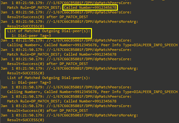
To watch the process the router uses to select the correct dial peer, use the debug voip dialpeer command.
The debug voip dialpeer command should be used only with great caution on a production system. The output generated can
overwhelm the console buffer, causing you to lose control of the router.
In the segment of the following output, you can see that the number 9912345678 matches the landlines dial peer tag 3 (landlines).
Task 5: Inbound Calls
Configure for Inbound Calls
To properly test pod-to-pod calls, we need to configure both RtrPod1 and RtrPod2 for inbound calling.
To allow inbound calls from the PSTN, two things need to occur:
- A dial peer must collect the called digits sent from the provider over the PRI trunk.
- The digit length must match the internal dial peers.
An "incoming" dial peer is created using the incoming called-number command to match the Dialed Number Identification Service (DNIS) from the trunk. Then the direct-inward-dial command uses the Direct Inward Dialing (DID) digits from the trunk to try to match dial peers (hopefully internal extensions).
| RtrPod1(config)#dial-peer voice 123 pots RtrPod1(config-dial-peer)#description Inbound Calls RtrPod1(config-dial-peer)#incoming called-number 5105555... RtrPod1(config-dial-peer)#direct-inward-dial RtrPod1(config-dial-peer)#port 0/0/0:23 RtrPod1(config-dial-peer)#exit |
RtrPod2(config)#dial-peer voice 123 pots RtrPod2(config-dial-peer)#description Inbound Calls RtrPod2(config-dial-peer)#incoming called-number 5105555... RtrPod2(config-dial-peer)#direct-inward-dial RtrPod2(config-dial-peer)#port 0/0/0:23 RtrPod2(config-dial-peer)#exit |
The PSTN simulator is configured to send the full 10-digit number inbound (even if the call was dialed as a 7-digit local number to reach the pod). Because the internal extensions are only 4-digit, the calls will fail unless incoming digits match the extensions. The fastest option to address this is to implement the dialplan-pattern command in telephony-service.
If you ever change the dialplan pattern, you must remove the previous one with the no command. Overwriting with a new version will not work!
| RtrPod1(config-telephony)#dialplan-pattern 1 5105555... extension-length 4 | RtrPod2(config-telephony)#dialplan-pattern 1 5105555... extension-length 4 |
While the dialplan-pattern command will automatically create full ten-digit dial peers from the ephone-dn extensions, it will not do the same for any dial peers that point to FXS ports. That is, if you have a POTS dial peer that sends extension 1234 to an FXS port, to make it reachable from the PSTN, a second POTS dial peer is needed with a destination pattern that matches the expected number of digits (5105551234, in this case).
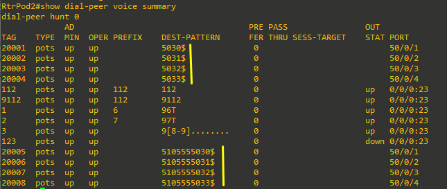
After the dialplan-pattern command is issued, you can enter the show dial-peer voice summary command to see the new 10-digit dial peers created for each 4-digit extension:
Since we have two pods, to make tests we will call the full local number of an IP Phone in the other pod. We want to make sure to answer the call, or the voice channels won't be used. To verify inbound calls, call from a phone in the other pod.
Following are the tests made, from RtrPod1 x5000 to RtrPod2 x5030, and viceversa using the full local E.164 DIDs:
Task 6: Calls over the WAN
An Ethernet connection will be used to simulate the WAN connection to allow the two pods to connect together.
Configure a WAN Connection
|
RtrPod1(config)# interface g0/1 RtrPod1(config-if)# ip address 10.0.0.1 255.255.255.0 RtrPod1(config-if)# no shut |
RtrPod2(config)# interface g0/1 RtrPod2(config-if)# ip address 10.0.0.2 255.255.255.0 RtrPod2(config-if)# no shut |
Configure Four-Digit VoIP Dial Peers to Other Pod Using the WAN
Careful crafting of the destination pattern is necessary to send the correct numbers to the right pod. You will need to craft a separate dial peer for each pod. Since we are using just 2 pods, this is easy. With VoIP dial peers, there is no digit stripping like there is with POTS dial peers, so there is no need for prefix or forward-digits commands:
| RtrPod1(config)#dial-peer voice 5030 voip RtrPod1(config-dial-peer)#description WAN calls to Pod 2 RtrPod1(config-dial-peer)#destination-pattern 50[3-5][0-9] RtrPod1(config-dial-peer)#session target ipv4:10.0.0.2 |
RtrPod2(config)#dial-peer voice 5000 voip RtrPod2(config-dial-peer)#description WAN calls to Pod 1 RtrPod2(config-dial-peer)#destination-pattern 50[0-2]. RtrPod2(config-dial-peer)#session target ipv4:10.0.0.1 |
Verify Calls to Other Pods Using the WAN
Verify that you can call extensions in the other pod by dialing just the 4-digit extension.
Task 7: PSTN Failover
Before we continue with this task, it is necessary to have configured the necessary translation rules to match de 7-digit numbers received on the PSTN_Simulator (please see Appendix E, latest section).
After users get accustomed to dialing four-digit extensions for other people in the company, a WAN failure will result in call failure, even though the PSTN connection is still working. PSTN failover allows the users to successfully dial the four-digit internal extensions even when the WAN is down; the calls are redirected using the PSTN.
Configure a PSTN Failover
As noted in Lab 6-4, Step 1-1, Rule 4, when two dial peers have the exact same destination pattern, they are selected at random. However, this can be controlled using the preference command. The higher the preference value, the less desirable the dial peer is. All dial peers have a default preference of 0, but this does not show in the running configuration. By creating a POTS dial peer that has the exact same destination pattern as the VoIP dial peer, but assigning a preference greater than 0, the VoIP dial peer will be preferred as long as the WAN is up. If the WAN fails, the router then looks for duplicate destination patterns with higher preferences. The only other thing to remember is that simply sending the remaining digits (after the default POTS digit-stripping behavior) will not be enough for the PSTN to route the call. This is where the prefix command is so useful. Not only can the stripped digits be preserved, but the other digits needed to complete the call can also be added to make a routable PSTN number (the same as if the call was dialed directly on a phone through the PSTN).
Continuing with both dial peers created in Task 6, and assuming both pods are reachable with 7-digit dialing, the following dial peers will allow failover for both pods. The leading 50 will be stripped by the normal POTS dial-peer behavior, and the prefix command adds the 555 exchange and restores the stripped 50 digits. Notice that the destination pattern is exactly the same as the one in the VoIP dial peer. Also note that a 9 is not needed for the prefix of this dial peer, because the call will be sent directly to the PRI, and not matched to another dial peer first.
| RtrPod1(config)# dial-peer voice 55550 pots RtrPod1(config-dial-peer)# description PSTN Failover Calls to Pod 2 RtrPodx(config-dial-peer)# destination-pattern 50[3-5]. RtrPodx(config-dial-peer)# prefix 55550 RtrPodx(config-dial-peer)# preference 1 RtrPodx(config-dial-peer)# port 0/0/0:23 RtrPodx(config-dial-peer)# exit |
RtrPod2(config)# dial-peer voice 55550 pots RtrPod2(config-dial-peer)# description PSTN Failover Calls to Pod 1 RtrPod2(config-dial-peer)# destination-pattern 50[0-2]. RtrPod2(config-dial-peer)# prefix 55550 RtrPod2(config-dial-peer)# preference 1 RtrPod2(config-dial-peer)# port 0/0/0:23 RtrPod2(config-dial-peer)# exit |
If the router knows that the IP address is unreachable (for example, the local interface is down), the call fails over immediately to the next-higher-preference dial peer. However, if the router is not sure that the route is down (for example, the remote interface is down, but connected through a switch or cloud, so the local interface is still up), the router will wait ten seconds by default before failover to ensure that there is no other path.
Now to try this, we will disconnect the cable between RtrPod1 and RtrPod2 and attempt to dial the same 4-digit extensions. Verify you can call between both pods. You can also verify that the PSTN is used, for if the call is answered, the console will show the PRI channel-in-use messages.
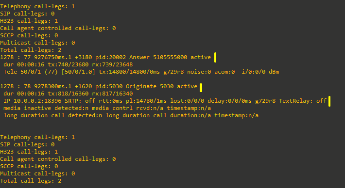 Normal call flow over WAN
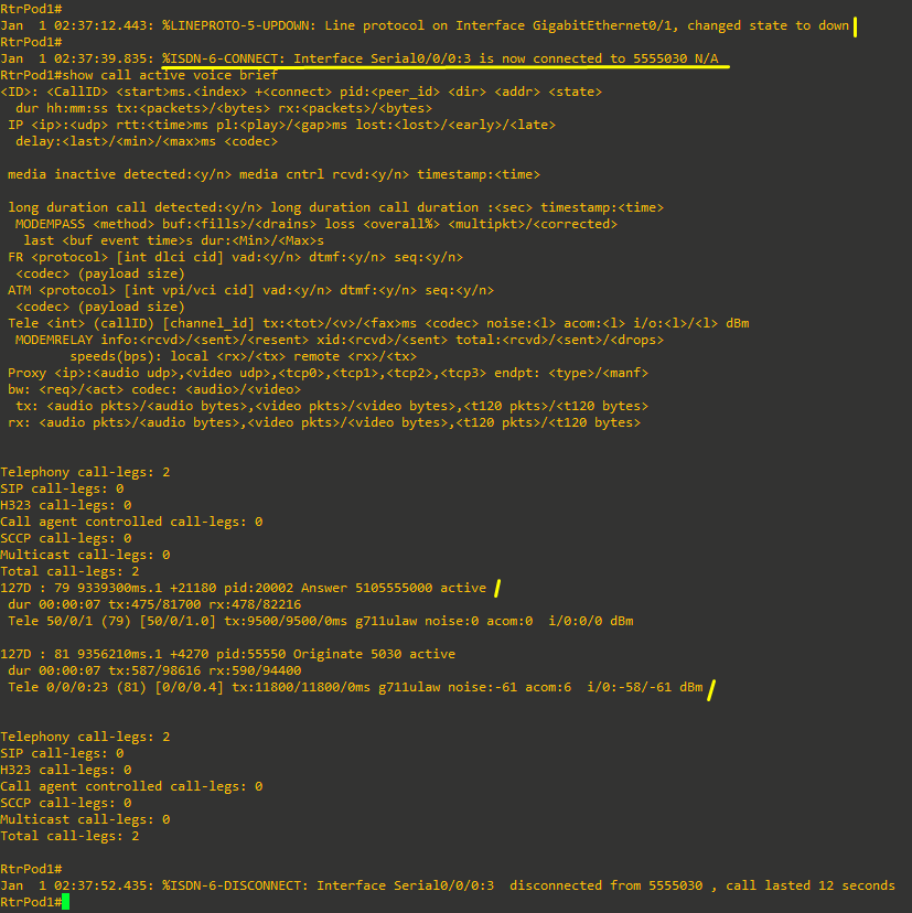 The WAN is disconnected, and the call is now going to the PSTN