
Lab 8-1: CleanAir and ED-RRM
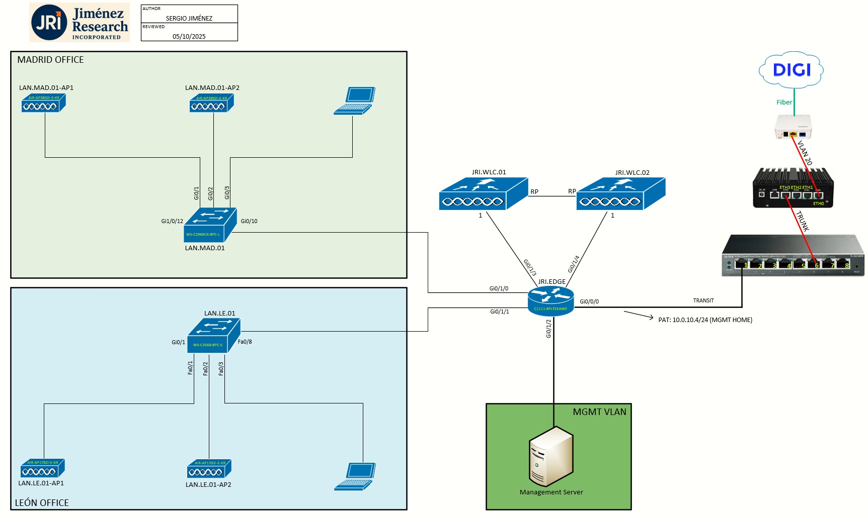
Topology
Task 0: Prerequisites for CleanAir
-
You can configure Cisco CleanAir only on CleanAir-enabled access points.
-
Only Cisco CleanAir-enabled access points using the following access point modes can perform Cisco CleanAir spectrum monitoring: Local, FlexConnect, Monitor, SE-Connect
An AP must be configured for either local or monitor mode before it can generate CleanAir interference reports. Reporting is not possible in the Spectrum Expert Connect (SE-Connect) mode.
Task 1: Enabling CleanAir
Cisco CleanAir is a spectrum intelligence solution designed to proactively manage the challenges of a shared wireless spectrum. It allows you to see all of the users of the shared spectrum (both native devices and foreign interferers). It also enables you or your network to act upon this information. For example, you could manually remove the interfering device, or the system could automatically change the channel away from the interference. CleanAir provides spectrum management and RF visibility.
A Cisco CleanAir system consists of CleanAir-enabled APs, Cisco WLCs, and Cisco Prime Infrastructure. These APs collect information about all devices that operate in the industrial, scientific, and medical (ISM) bands, identify and evaluate the information as a potential interference source, and forward it to the WLC. The WLC controls the APs, collects spectrum data, and forwards information to Cisco Prime Infrastructure or Cisco Connected Mobile Experiences (CMX) upon request.
For every device operating in the unlicensed band, Cisco CleanAir tells you what it is, where it is, how it is impacting your wireless network, and what actions you or your network should take. It simplifies RF so that you do not have to be an RF expert. Wireless LAN systems operate in unlicensed 2.4- and 5-GHz ISM bands. Many devices, such as microwave ovens, cordless phones, and Bluetooth devices also operate in these bands and can negatively affect Wi-Fi operations. Some of the most advanced WLAN services, such as voice over wireless and IEEE 802.11n radio communications, could be significantly impaired by the interference caused by other legal users of the ISM bands. The integration of Cisco CleanAir functionality into the Cisco Unified Wireless Network addresses this problem of radio frequency (RF) interference.
To configure CleanAir on the WLC:
Step 1: Choose Wireless > 802.11a/n/ac or 802.11b/g/n > CleanAir to open the 802.11a (or 802.11b) > CleanAir page.
Check the CleanAir check box to enable Cisco CleanAir functionality on the 802.11a/n or 802.11b/g/n network, or uncheck it to prevent the controller from detecting spectrum interference. By default, this feature is in disabled state.
Check the Report Interferers check box to enable the Cisco CleanAir system to report any detected sources of interference, or uncheck it to prevent the controller from reporting interferers. By default, this feature is in enabled state.
Device Security alarms, Event Driven RRM, and the Persistence Device Avoidance algorithm do not work if Report Interferers are disabled.
Check the Persistent Device Propagation check box to enable propagation of information about persistent devices that can be detected by CleanAir. Persistent device propagation enables you to propagate information about persistent devices to the neighboring APs connected to the same controller. Persistent interferers are present at the location and interfere with the WLAN operations even if they are not detectable at all times.
|
|
|
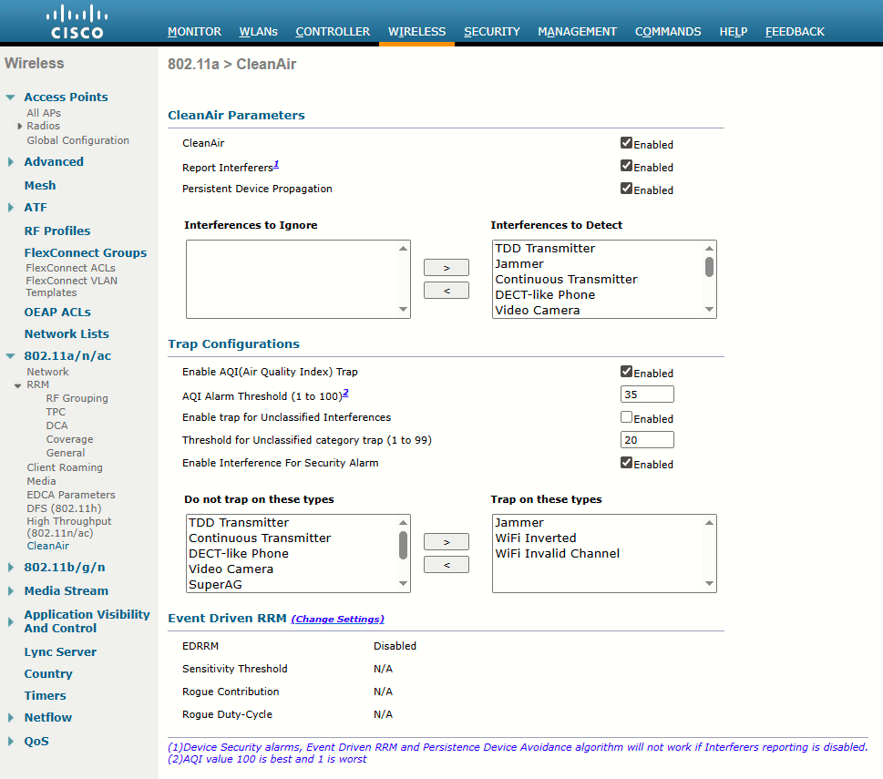
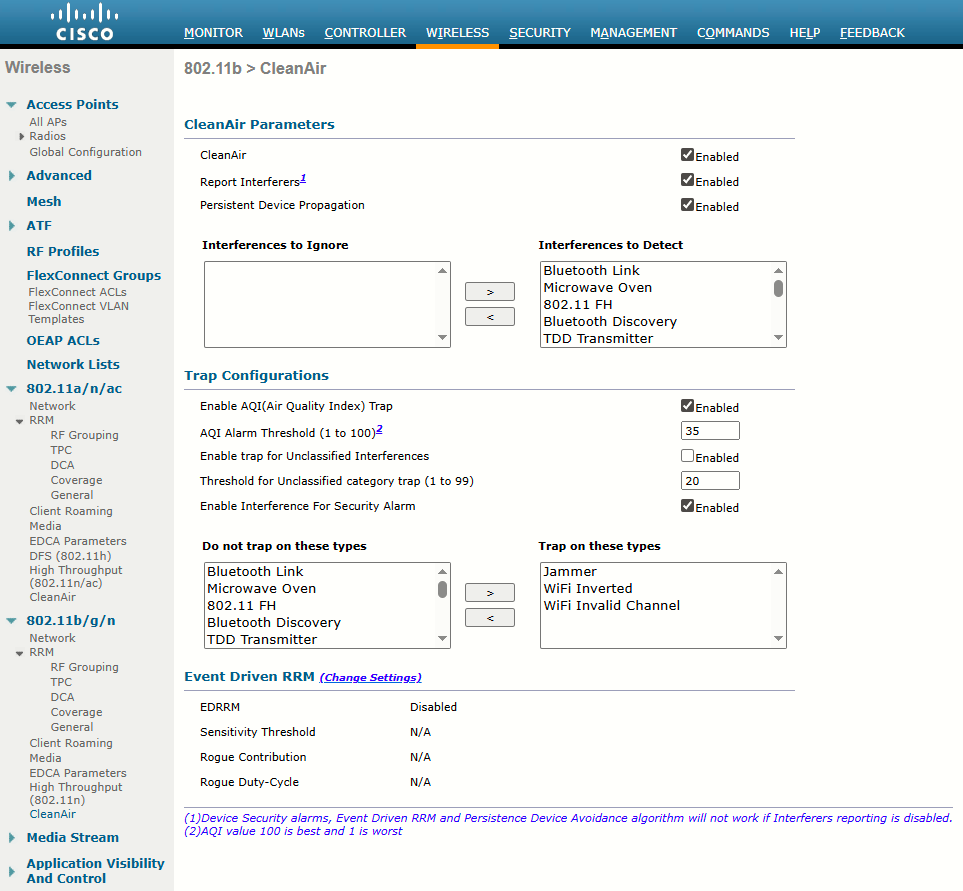
Step 2: Ensure that any sources of interference that need to be detected and reported by the Cisco CleanAir system appear in the Interferences to Detect box and any that do not need to be detected appear in the Interferences to Ignore box. By default, all interference sources are detected. The possible sources of interference that you can choose are as follows:
- Bluetooth Paging Inquiry—A Bluetooth discovery (802.11b/g/n only)
- Bluetooth Sco Acl—A Bluetooth link (802.11b/g/n only)
- Generic DECT—A digital enhanced cordless communication (DECT)-compatible phone
- Generic TDD—A time division duplex (TDD) transmitter
- Generic Waveform—A continuous transmitter
- Jammer—A jamming device
- Microwave—A microwave oven (802.11b/g/n only)
- Canopy—A canopy bridge device
- Spectrum 802.11 FH—An 802.11 frequency-hopping device (802.11b/g/n only)
- Spectrum 802.11 inverted—A device using spectrally inverted Wi-Fi signals
- Spectrum 802.11 non std channel—A device using nonstandard Wi-Fi channels
- Spectrum 802.11 SuperG—An 802.11 SuperAG device
- Spectrum 802.15.4—An 802.15.4 device (802.11b/g/n only)
- Video Camera—An analog video camera
- WiMAX Fixed—A WiMAX fixed device (802.11a/n/ac only)
- WiMAX Mobile—A WiMAX mobile device (802.11a/n/ac only)
- XBox—A Microsoft Xbox (802.11b/g/n only)
APs that are associated with the controller send interference reports only for the interferers that appear in the Interferences to Detect box. This functionality allows you to filter out interferers that you do not want as well as any that may be flooding the network and causing performance problems for the controller or Prime Infrastructure. Filtering allows the system to resume normal performance levels.
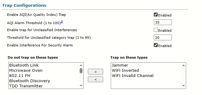
Step 3: Configure Cisco CleanAir alarms as follows:
- Ensure that any sources of interference that need to trigger interferer alarms appear in the Trap on These Types box and any that do not need to trigger interferer alarms appear in the Do Not Trap on These Types box. By default, all interference sources trigger interferer alarms. For example, if you want the controller to send an alarm when it detects a jamming device, check the Enable Interference Type Trap check box and move the jamming device to the Trap on These Types box.
Task 2: Monitoring Interference Devices
As interference sources are detected and classified according to interference type, the AP also measures the RSSI and the duty cycle of the interferer. The duty cycle is the percentage of time the source is transmitting on the channel, which indicates its persistence or how much of the airtime the interferer is consuming. The AP combines the RSSI and duty cycle into a severity index value. Severity ranges from 0 (not severe) to 100 (very severe). Interference with a high severity rating can render a channel unusable.
Step 1: Choose to open the CleanAir > Interference Devices page:
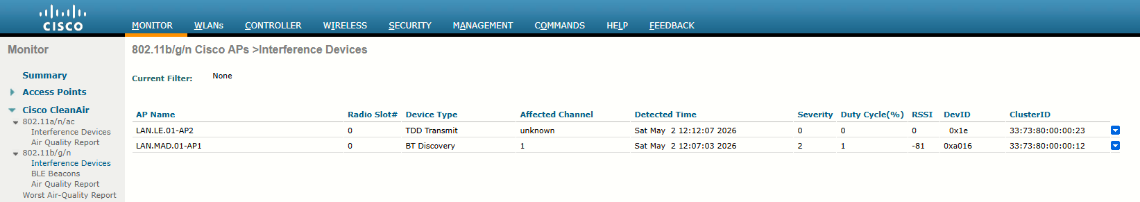
This page shows the following information:
-
AP Name: The name of the access point where the interference device is detected.
-
Radio Slot #: Slot where the radio is installed.
-
Interferer Type: Type of the interferer.
-
Affected Channel: Channel that the device affects.
-
Detected Time: Time at which the interference was detected.
-
Severity: Severity index of the interfering device.
-
Duty Cycle (%): Proportion of time during which the interfering device was active.
-
RSSI: Receive signal strength indicator (RSSI) of the access point.
-
DevID: Device identification number that uniquely identified the interfering device.
-
ClusterID: Cluster identification number that uniquely identifies the type of the devices.
Interference detection reports sent to a controller include the AP name, interference type, affected channel, time stamp, severity, duty cycle, and RSSI. The controller then tries to determine whether the same interference source is involved in reports coming from multiple APs. If so, the source is uniquely identified by assigning it a cluster ID. A cluster ID is actually a pseudo-MAC address that represents the non-802.11 device with a familiar wireless identifier.
Task 3: Air-Quality Index
As APs and controllers work together to generate a list of interference reports, the list can grow quite long. To get a feel for the RF conditions on any one channel and AP, you would have to read through the list of reports manually and guess the cumulative effect that various interferers were having.
Cisco WLCs can do a better analysis by calculating an air-quality index (AQI) for each AP and its channels. The AQI indicates Wi-Fi health within an AP’s cell, as indicated by a scale from 0 (unusable) to 100 (perfect).
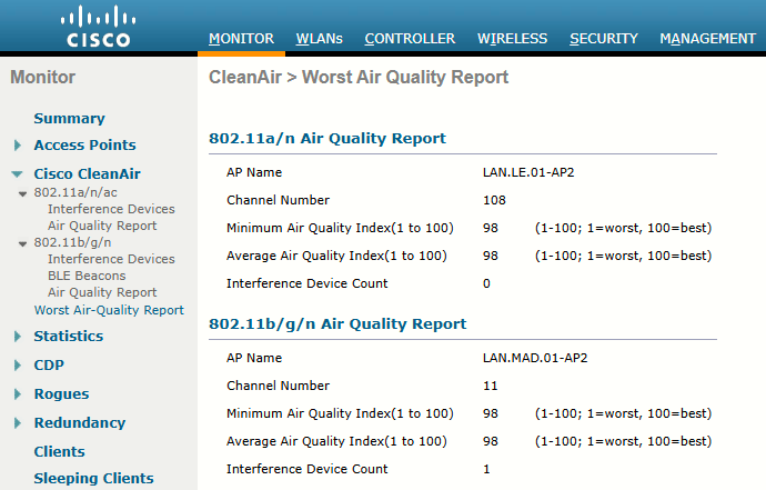
Step 1: You can display the air quality metrics for every AP on a controller by selecting Monitor > CleanAir > 802.11a/n/ac or 802.11b/g/n > CleanAir > Air Quality Report. You can see a summary of the AP with the worst air-quality rating in each band by selecting Worst Air-Quality Report:
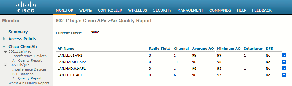
Air-quality ratings are updated dynamically. Each AP measures RF conditions once a second and then calculates an air quality value every 15 seconds and a summary every 30 seconds. By default, these values are reported to the AP’s controller every 15 minutes.
Step 2: You can also view an AP’s CleanAir activity more frequently through the rapid update mode. To access this mode, use Monitor > Access Points > 802.11a/n/ac or 802.11b/g/n to display a list of APs. Choose an AP, and then select CleanAir from the blue triangular drop-down menu on the right side of the list. In rapid update mode, the controller automatically refreshes the page every 30 seconds with updated CleanAir data:
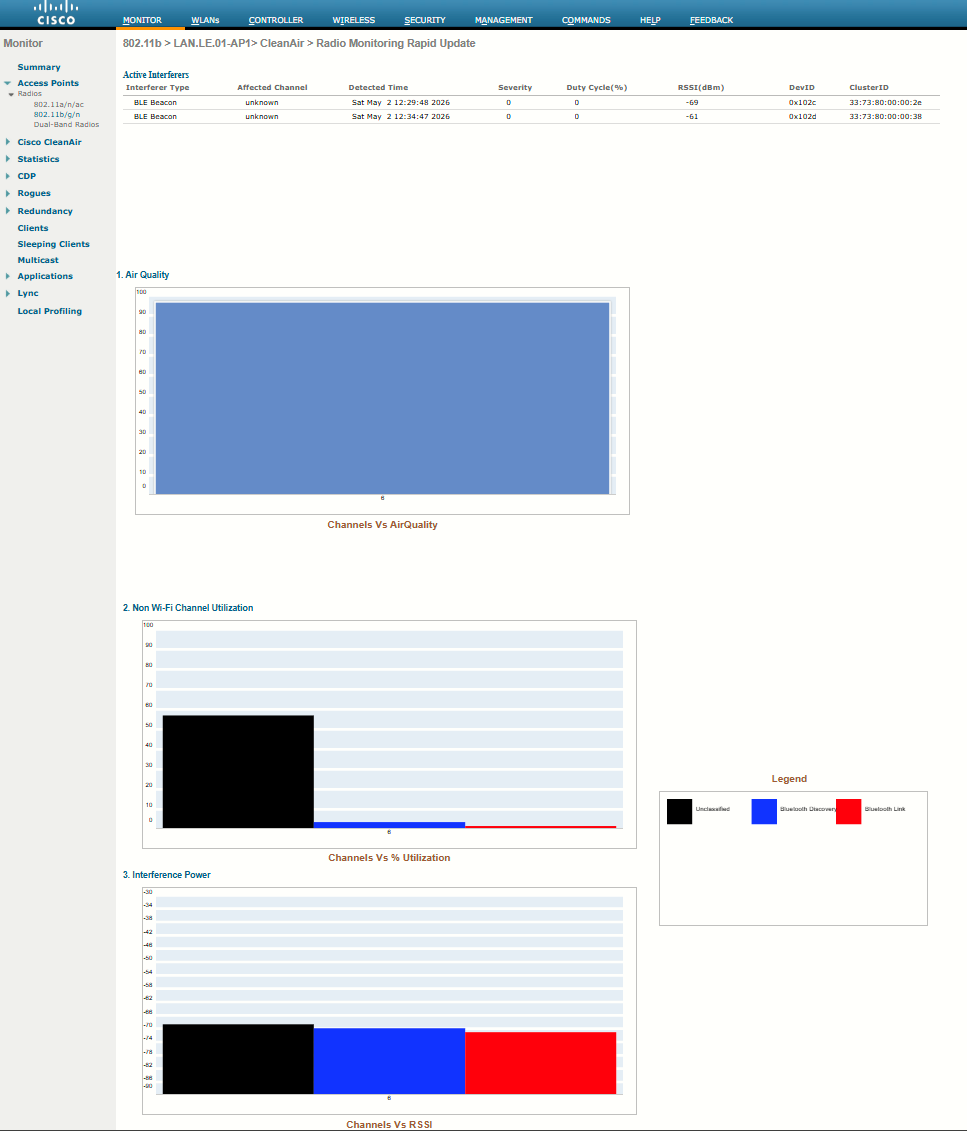
Rapid update mode also shows more detailed CleanAir information from an AP. The air quality is shown as a bar graph. Normally only the one channel used by an AP is shown; if the AP is in monitor mode, all channels are shown. The same page also shows channel utilization and interference power measured by the AP. Controllers display air quality on a per-AP (and channel) basis, and this information is aggregated further by Prime Infrastructure (PI). Air quality is summarized for the entire set of controllers managed in the enterprise.
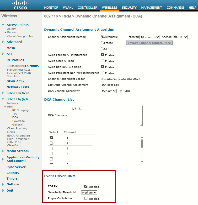
Task 4: Using Event-Driven RRM
CleanAir enabled is a prerequisite for ED-RRM
By default, APs and controllers work together to detect, classify, and report wireless interference from non-802.11 devices. CleanAir and RRM can work together so that controllers actually take some action on interference events at the regular RRM intervals. By default, RRM runs the dynamic channel allocation (DCA) algorithm every 10 minutes, but you can increase the interval up to 24 hours. If non-802.11 interference occurs near an AP, the controller must wait until the next DCA interval before it can move the AP away from the unusable channel.
When Event-Driven RRM (ED-RRM) is enabled, the normal periodic RRM DCA process is triggered immediately in response to interference reported by an AP. ED-RRM must be enabled and then triggered based on an AQI threshold. You can set the threshold to Low (AQI 35), Medium (AQI 50), or High (AQI 60).
Step 1: First, enable ED-RRM globally on a controller. ED-RRM uses the DCA function to change an AP’s channel and work out any other channel allocation changes that might be needed.
Sources
Cisco Wireless Controller Configuration Guide, Release 8.5, Chapter: Radio Resource Management
https://www.cisco.com/c/en/us/td/docs/wireless/controller/8-5/config-guide/b_cg85/radio_resource_management.html#ID893
Event Driven RRM
https://mrncciew.com/2013/05/02/event-driven-rrm/
Cisco CleanAir - Cisco Unified Wireless Network Design Guide
https://www.cisco.com/c/en/us/support/docs/wireless/5500-series-wireless-controllers/112139-cleanair-uwn-guide-00.html