
Lab 4-1: Adding a Second WLC to the Lab (CLI Configuration Wizard Method)
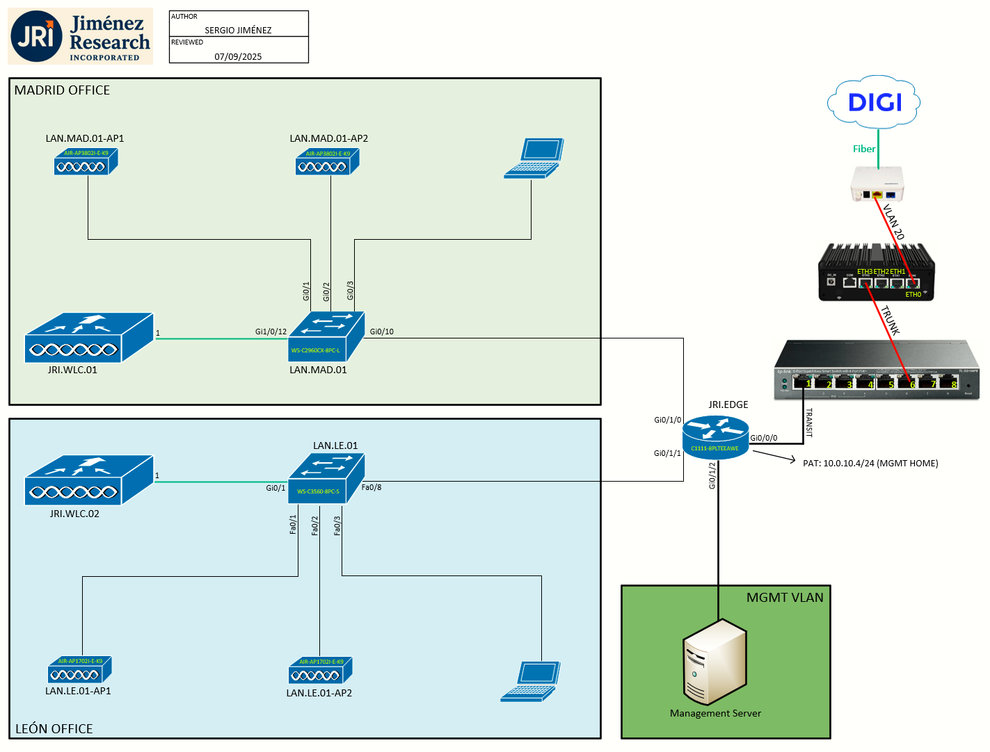
Topology
Task 1: JRI.WLC.02 Bootup, Factory Reset
We have already setup the JRI.WLC.01 (which will be the main WLC for this lab). Now I want to initialize and setup what will become the secondary WLC, JRI.WLC.02.
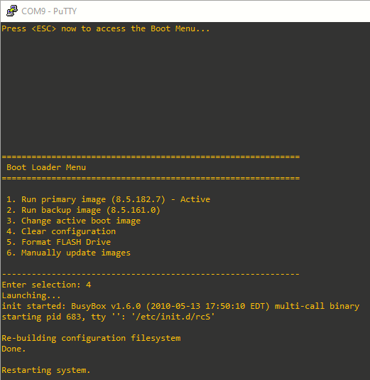
As in Lab 2-1, first task is to bring the WLC up and have it factory reset. The controller bootloader (ppcboot) must be accessed by pressing Esc key during the boot process on the WLC. We are prompted to choose an option from the following, where we'll choose 4. Clear configuration:
Task 2: Configuring the Controller—Using the CLI Configuration Wizard
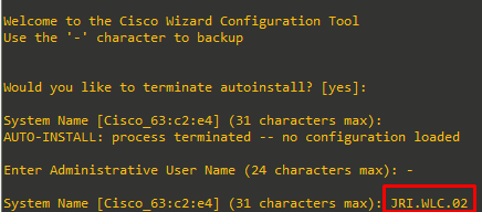
Since I used WLAN Express Setup (wired method) on Lab 2-1 for JRI.WLC.01, I'll use the CLI Configuration Wizard method here. After the prompt appears, I'll press any key to terminate AutoInstall, and start the CLI Configuration Wizard. Before we begin:
- The available options are displayed in brackets after each configuration parameter. The default value is displayed in all uppercase letters
-
If you enter an incorrect response, an appropriate error message is displayed, such as Invalid Response, and returns you to the wizard prompt.
-
Press the hyphen key ( - ) if you ever need to return to the previous command line.
Step 1: Already said, but when prompted to terminate the AutoInstall process, enter yes. If you do not enter yes, the AutoInstall process begins after 30 seconds.
The AutoInstall feature downloads a configuration file from a TFTP server and then loads the configuration onto the controller automatically.
Step 2: Enter the system name, which is the name that you want to assign to the controller.
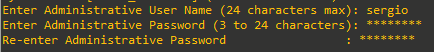
Step 3: Enter the administrative username and password to be assigned to this controller
Step 4: If you want the controller’s service-port interface to obtain an IP address from a DHCP server, enter DHCP. If you do not want to use the service port or if you want to assign a static IP address to the service port, enter none.
The service-port interface controls communications through the service port. Its IP address must be on a different subnet from the management interface. This configuration enables you to manage the controller directly or through a dedicated management network to ensure service access during network downtime.

I'll enter DHCP. Then, the controller will use its internal DHCP server (started at bootup), to serve clients connected to the service port:

Step 5: Enable or disable link aggregation (LAG) by choosing yes or NO.

Here I chose yes, differing from JRI.WLC.01. LAG will be explained later.
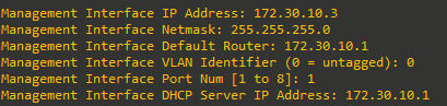
Step 6. Enter the IP address of the management interface, netmask, and default router. Then introduce the VLAN identifier and the mgmt. interface port number. Finally, introduce the DHCP Server IP address (we'll set it to the default gateway).
The management interface is the default interface for in-band management of the controller and connectivity to enterprise services such as AAA servers.
Step 7: Enable HA (or not).

We'll leave this as NO, because it will be done on a later lab.
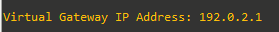
Step 8: Enter the IP address of the controller’s virtual interface. You should enter a fictitious unassigned IP address.
The virtual interface is used to support mobility management, DHCP relay, and embedded Layer 3 security such as guest web authentication and VPN termination. All controllers within a mobility group must be configured with the same virtual interface IP address.
I will configure the same virtual IP address I configured on JRI.WLC.01:
Step 9: Enter the name of the mobility group/RF group to which you want the controller to belong.
Although the name that you enter here is assigned to both the mobility group and the RF group, these groups are not identical. Both groups define clusters of controllers, but they have different purposes. All of the controllers in an RF group are usually also in the same mobility group and vice versa. However, a mobility group facilitates scalable, system-wide mobility and controller redundancy while an RF group facilitates scalable, system-wide dynamic RF management.
I will enter Default, to match the one on JRI.WLC.01:

Step 10: Enter the network name or service set identifier (SSID). The SSID enables basic functionality of the controller and allows access points that have joined the controller to enable their radios. Configure also DHCP Bridging Mode and the allowance of static IP addresses.
To match the addressing plan and lab guide on Lab 1-1, the SSID will be called LEON_USERS:
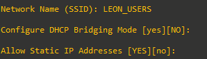
DHCP Bridging Mode will be left to default of NO (this requires clients to request an IP address from a DHCP server).
Allow Static IP Addresses will be left to default of yes (this allows WiFi clients on the network with static IP addresses configured, because we reserved a portion of the LEON_USERS network for static IP addresses).
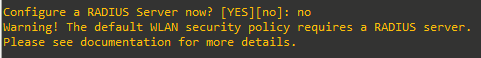
Step 11: To configure a RADIUS server now, enter YES and then enter the IP address, communication port, and secret key of the RADIUS server. Otherwise, enter no. If you enter no, the following message is displayed: Warning! The default WLAN security policy requires a RADIUS server. Please see the documentation for more details.
Step 12: Enter the code for the country in which the controller will be used.
Enter help to view the list of available country codes. Multiple codes can be entered. APs would need to be assigned to specific one.

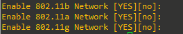
Step 13: Enable or disable the 802.11b, 802.11a, and 802.11g lightweight access point networks by entering YES or no.
Step 14: Enable or disable the controller’s radio resource management (RRM) auto-RF feature by entering YES or no.
The auto-RF feature enables the controller to automatically form an RF group with other controllers. The group dynamically elects a leader to optimize RRM parameter settings, such as channel and transmit power assignment, for the group.

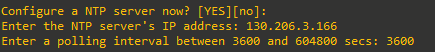
Step 15: If you want the controller to receive its time setting from an external Network Time Protocol (NTP) server when it powers up, enter YES to configure an NTP server. Otherwise, enter no.
hora.rediris.es NTP server IP is configured:
Step 16: IPv6 configuration

Step 17: When prompted to verify that the configuration is correct, enter yes or NO. The controller saves your configuration when you enter yes, reboots, and prompts you to log on.

Since we enabled LAG, the configuration is not finished until we correctly configure the other end (the switch). I will explain this on the next lab (Lab 4-2).