Lab 6-2: Configuring Radio Resource Managament (RRM)
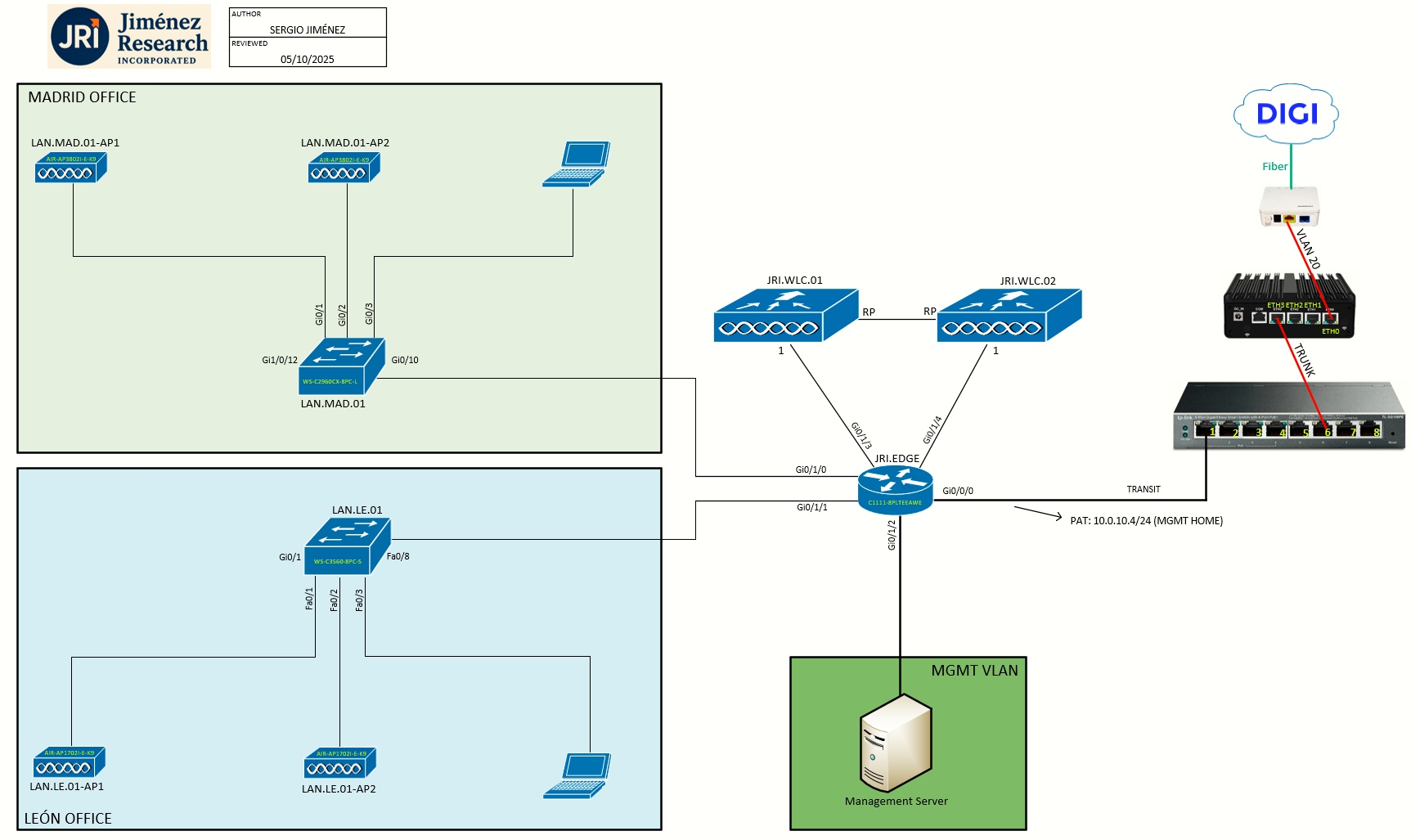
Topology
Task 1: Information about Radio Resource Management
The Radio Resource Management (RRM) software embedded in the WLC acts as a built-in RF engineer to consistently provide real-time RF management of your wireless network. RRM enables WLCs to continually monitor their associated LAPs for the following information:
-
Traffic load: The total bandwidth used for transmitting and receiving traffic. It enables wireless LAN managers to track and plan network growth ahead of client demand.
-
Interference: The amount of traffic coming from other 802.11 sources.
-
Noise: The amount of non-802.11 traffic that is interfering with the currently assigned channel.
-
Coverage: The received signal strength (RSSI) and signal-to-noise ratio (SNR) for all connected clients.
-
Other: The number of nearby access points.
Using this information, RRM can periodically reconfigure the 802.11 RF network for best efficiency. To do this, RRM performs these functions:
-
Radio resource monitoring (RRM)
-
Transmit power control (TPC)
-
Dynamic channel assignment (DCA)
-
Coverage hole detection and correction (CHDC)
Task 2: Radio Resource Monitoring (RRM)
RRM automatically detects and configures new WLCs and LAPs as they are added to the network. It then automatically adjusts associated and nearby LAPs to optimize coverage and capacity.
LAPs can simultaneously scan all valid 5-GHz and 2.4-GHz channels for the country of operation as well as for channels available in other locations. The APs go “off-channel” for a period not greater than 60 ms to monitor these channels for noise and interference. Packets collected during this time are analyzed to detect rogue access points, rogue clients, ad-hoc clients, and interfering access points.
By default, each radio spends less than 2% of its time off channel.
Benefits of RRM
RRM produces a network with optimal capacity, performance, and reliability. It frees you from having to continually monitor the network for noise and interference problems, which can be transient and difficult to troubleshoot. RRM ensures that clients enjoy a seamless, trouble-free connection throughout the Cisco unified wireless network.
RRM uses separate monitoring and control for each deployed network: 5 GHz and 2.4 GHz. The RRM algorithms run separately for each radio type (5 GHz and 2.4 GHz). RRM uses both measurements and algorithms.
- RRM measurements can be adjusted using monitor intervals, but they cannot be disabled.
- RRM algorithms are enabled automatically but can be disabled by statically configuring channel and power assignment. The RRM algorithms run at a specified updated interval, which is 600 seconds by default.
About Configuring RRM
The controller’s preconfigured RRM settings are optimized for most deployments. However, you can modify the controller’s RRM configuration parameters at any time through either the GUI or the CLI.
You can configure these parameters on controllers that are part of an RF group or on controllers that are not part of an RF group.
The RRM parameters should be set to the same values on every controller in an RF group. The RF group leader can change as a result of controller reboots or depending on which radios hear each other. If the RRM parameters are not identical for all RF group members, varying results can occur when the group leader changes.
Using the controller GUI, you can configure the following RRM parameters:
- RF group mode
- TPC
- DCA
- CHDC
- Profile Thresholds
- Monitoring Channels
- Monitor Intervals.
Configuring RF Groups
An RF group is a logical collection of controllers that coordinate to perform RRM in a globally optimized manner to perform network calculations on a per-radio basis. Separate RF groups exist for 2.4-GHz and 5-GHz networks. Since we are using two controllers in HA SSO mode, only one logical unit is available, hence JRI.WLC.01 will be the leader of the RF group.
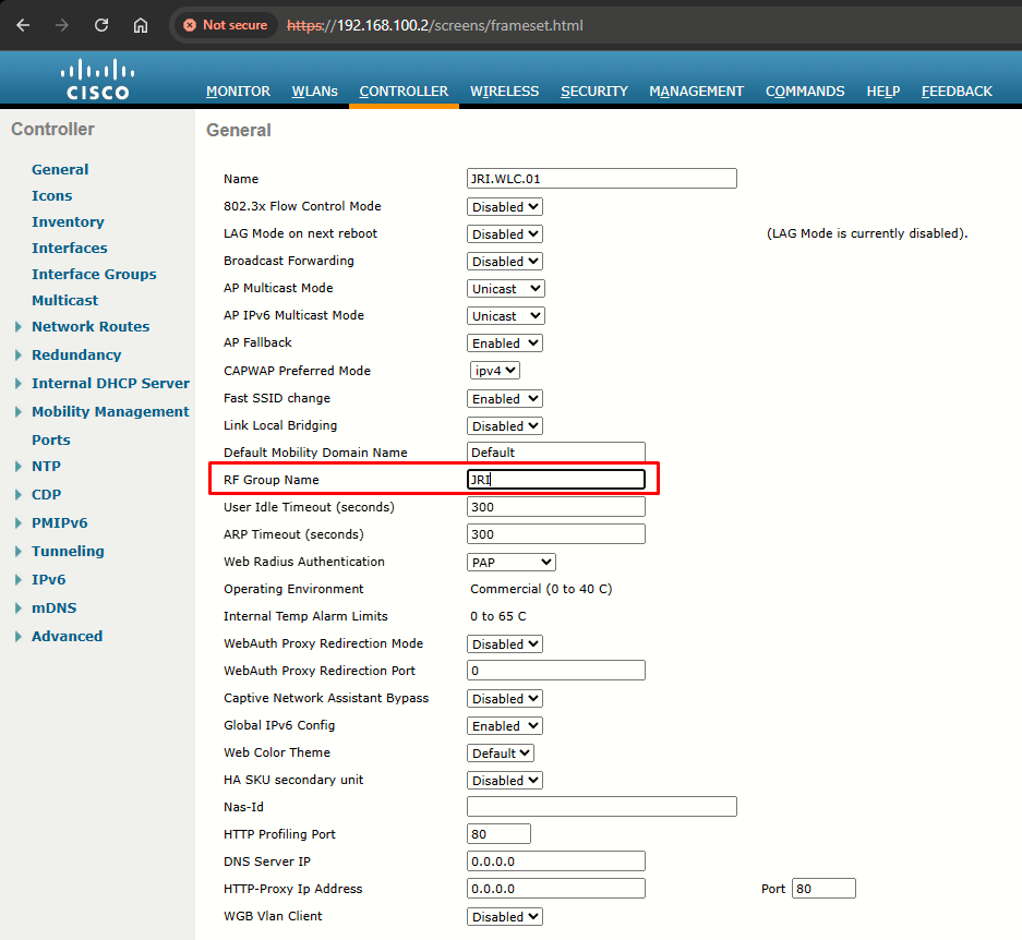
A controller is configured in an RF group name, which is sent to all the APs joined to the controller and used by the APs as the shared secret for generating the hashed MIC in the neighbor messages. To create an RF group, you configure all of the controllers to be included in the group with the same RF group name.
Step 1: To change the RF Group Name, go to Controller > General. Here, I have changed the name from Default to JRI:
Step 2: Configuring RF Group Mode can be done at Wireless > (band) > RRM > RF Grouping:
Group Mode can be set to auto, leader or off:
- auto: Sets the RF group selection to automatic update mode. Best practice / safer option.
- leader: Sets the RF group selection to static mode, and sets this controller as the group leader.
- off: Sets the RF group selection off. Every controller optimizes its own access point parameters.
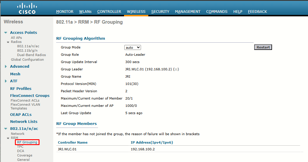
Here, we only have one unit (a pair really, since configured in HA SSO) -> JRI.WLC.01
Task 3: Transmit Power Control (TPC)
The WLC dynamically controls APs transmit power based on real-time wireless LAN conditions. The Transmit Power Control (TPC) algorithm increases and decreases an AP power in response to changes in the RF environment. In most instances, TPC seeks to lower an AP power to reduce interference, but in the case of a sudden change in the RF coverage, for example, if an AP fails or becomes disabled, TPC can also increase power on the surrounding APs.
This feature is different from coverage hole detection, which is primarily concerned with clients. TPC provides enough RF power to achieve the required coverage levels while avoiding channel interference between APs.
We recommend that you select TPCv1; TPCv2 option is deprecated. With TPCv1, you can select the channel aware mode; we recommend that you select this option for 5 GHz, and leave it unchecked for 2.4 GHz.
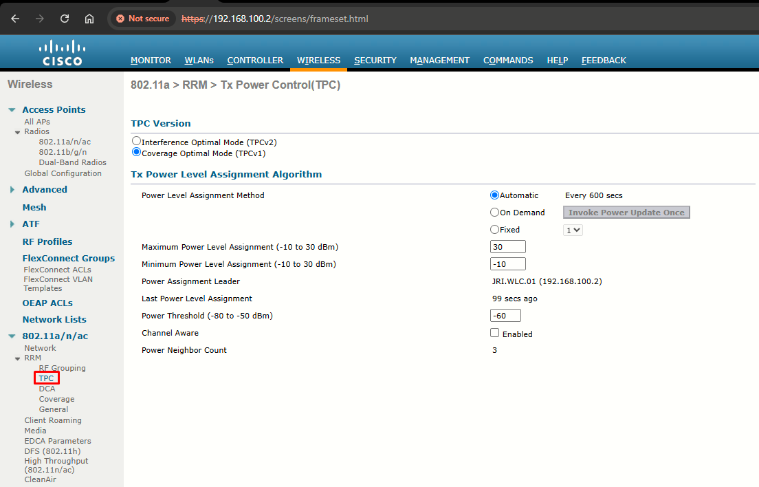
- Interference Optimal Mode (TCPv2): For scenarios where voice calls are extensively used. Goal is minimum interference. In this mode, there could be higher roaming delays and coverage hole incidents. Only use this in cases where RF issues cannot be resolved using TCPv1.
- Coverage Optimal Mode (TCPv1): Default mode. Offers strong signal coverage and stability. In this mode, power can be kept low to gain extra capacity and reduce interference.
From the image above, choose one of the following options from the Power Level Assignment Method:
- Automatic: The WLC periodically evaluates and if necessary, updated the Tx power for all joined APs. Default mode and best practice for optimal performance.
- On Demand: Same as automatic, but the WLC updated the Tx power if necessary, only when clicking Invoke Power Update Once.
- Fixed: Prevents WLC from evaluating or updating Tx power (which is set to the fixed value chosen from the drop-down list).
In the Power Threshold text box, enter the cutoff signal level used by RRM when determining whether to reduce an AP power. The default value for this parameter is –60 dBm for TPCv1, but can be changed when APs are transmitting at higher (or lower) than desired power levels. The range for this parameter is –80 to –50 dBm. Increasing this value (above -60 dBm) causes the APs to operate at a higher transmit power. Decreasing the value has the opposite effect.
In applications with a dense population of access points, it may be useful to decrease the threshold to –80 or –75 dBm to reduce the number of BSSIDs (APs) and beacons seen by the wireless clients. Some wireless clients might have difficulty processing a large number of BSSIDs or a high beacon rate and might exhibit problematic behavior with the default threshold.
This page also shows the following nonconfigurable transmit power level parameter settings:
-
Power Neighbor Count: The minimum number of neighbors an AP must have for the TCP algorithm to run.
-
Power Assignment Leader: The IP address of the RF group leader, which is responsible for power level assignment.
-
Last Power Level Assignment: The last time RRM evaluated the current transmit power level assignments.
Task 4: Dynamic Channel Assignment (DCA)
Two adjacent access points on the same channel can cause either signal contention or signal collision. In a collision, data is not received by the access point. This functionality can become a problem, for example, when someone reading an e-mail in a café affects the performance of the access point in a neighboring business. Even though these are separate networks, someone sending traffic to the café on channel 1 can disrupt communication in an enterprise using the same channel. Controllers can dynamically allocate access point channel assignments to avoid conflict and increase capacity and performance. Channels are reused to avoid wasting scarce RF resources. In other words, channel 1 is allocated to a different access point far from the café, which is more effective than not using channel 1 altogether. The DCA algorithm can work out optimum solutions automatically for all APs in an RF group.
DCA does not just solve the channel layout puzzle once for all APs. The algorithm runs every 10 minutes by default, so that it can detect any conditions that might require an AP’s channel to change. APs in the RF group are monitored for the metrics listed that can influence the channel reassignment decision:
| METRIC | DEFAULT STATE | DESCRIPTION |
| RSSI of neighboring APs | Always enabled | If DCA detects co-channel interference, it may move an AP to a different channel. |
| 802.11 interference | Enabled | If transmissions from APs and devices that are not part of the wireless network are detected, DCA may choose to move an AP to a different channel. |
| Non-802.11 noise | Enabled | If excessive noise is present on a channel, DCA may choose to avoid using it. |
| AP traffic load | Disabled | If an AP is heavily used, DCA may not change its channel to keep client disruption to a minimum. |
| Persistent interference | Disabled | If an interference source with a high duty cycle is detected on a channel, DCA may choose to avoid using it. |
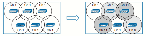
When a new AP first powers up, it uses the first non-overlapping channel in each band— channel 1 for 2.4 GHz and channel 36 for 5 GHz. Consider a simplistic scenario where all APs are new and powered up for the first time. You would end up with a building full of overlapping cells competing for the use of 2.4-GHz channel 1, as shown in the image below. The DCA algorithm works to correct this situation by finding a channel that each AP in the RF group can use without overlapping or interfering with other APs. Like TPC, DCA works out one channel layout in the 2.4-GHz band and another layout in the 5-GHz band.
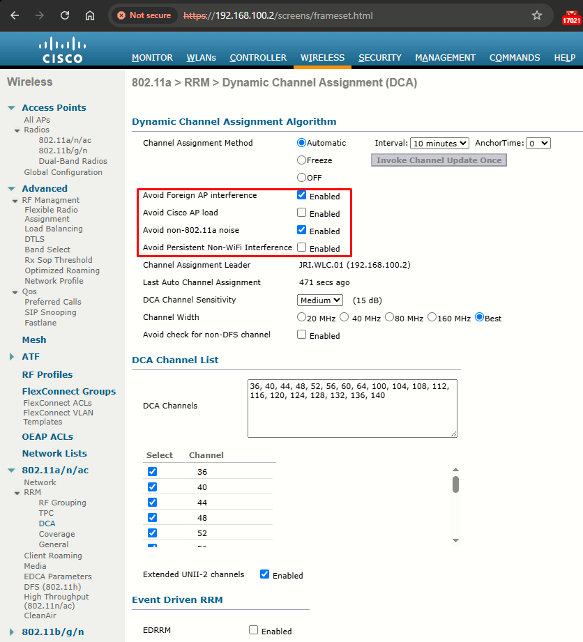
DCA configuration (GUI)
Step 0: Disable the 802.11 networks (802.11a/n/ac and/or 802.11b/g/n).
Step 1: Choose one of the following options from the Channel Assignment Method drop-down list to specify the WLCs DCA mode:
- Automatic: Causes the WLC to periodically evaluate and, if necessary, update the channel assignment for all joined APs. Default value.
- Freeze: Causes the WLC to evaluate and update the channel assignment for all joined APs, if necessary, but only when you click Invoke Channel Update Once.
The controller does not evaluate and update the channel assignment immediately after you click Invoke Channel Update Once. It waits for the next interval to elapse.
- OFF: Turns off DCA and sets all APs radios to the first channel of the band, which is the default value. If you choose this option, you must manually assign channels on all radios.
For optimal performance, we recommend that you use the Automatic setting.
Step 2: From the Interval drop-down list, choose one of the following options to specify how often the DCA algorithm is allowed to run: 10 minutes, 1 hour, 2 hours, 3 hours, 4 hours, 6 hours, 8 hours, 12 hours, or 24 hours. The default value is 10 minutes.
Step 3: From the AnchorTime drop-down list, choose a number to specify the time of day when the DCA algorithm is to start. The options are numbers between 0 and 23 (inclusive) representing the hour of the day from 12:00 a.m. to 11:00 p.m.
Step 4: Check the Avoid Foreign AP Interference check box to cause the controller’s RRM algorithms to consider 802.11 traffic from foreign APs (those not included in your wireless network) when assigning channels to LAPs, or uncheck it to disable this feature. For example, RRM may adjust the channel assignment to have APs avoid channels close to foreign APs. The default value is Enabled.
Step 5: Check the Avoid Cisco AP Load check box to cause the controller’s RRM algorithms to consider 802.11 traffic from APs in your wireless network when assigning channels, or uncheck it to disable this feature. For example, RRM can assign better reuse patterns to APs that carry a heavier traffic load. The default value is unselected.
Step 6: Check the Avoid Non-802.11a (802.11b) Noise check box to cause the controller’s RRM algorithms to consider noise (non-802.11 traffic) in the channel when assigning channels to lightweight access points, or uncheck it to disable this feature. For example, RRM may have access points avoid channels with significant interference from nonaccess point sources, such as microwave ovens. The default value is selected.
Step 7: Check the Avoid Persistent Non-WiFi Interference check box to configure the controller to stop ignoring persistent non-Wi-Fi interference in new channel calculation. The persistent non-Wi-Fi interference is considered during the metric calculation for channels.
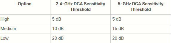
Step 8: From the DCA Channel Sensitivity drop-down list, choose one of the following options to specify how sensitive the DCA algorithm is to environmental changes such as signal, load, noise, and interference when determining whether to change channels:
- Low: The DCA algorithm is not particularly sensitive to environmental changes.
- Medium: The DCA algorithm is moderately sensitive to environmental changes.
- High: The DCA algorithm is highly sensitive to environmental changes.
The default value is Medium. The DCA sensitivity thresholds vary by radio band, as noted in the table below.
Step 9: For 802.11a/n/ac: leave Channel Width on Best (selects the best bandwidth suitable).
Step 10: Reenable the 802.11 networks that had been disabled at Step 0.
Task 5: Coverage Hole Detection and Correction (CHDC)
The RRM CHDC algorithm is a feature in WLANs that detects areas of radio coverage with insufficient radio coverage for robust radio performance. This feature alerts you when you need to add or relocate a lightweight AP.
CHDC is useful in two cases:
- Extending coverage in a weak area.
- Rapidly healing a coverage hole caused by an AP or radio failure, sooner than the TPC algorithm can detect and correct.
If clients on a lightweight AP are detected at threshold levels such as RSSI, failed client count, percentage of failed packets, and number of failed packets that are lower than those specified in the RRM configuration, the AP sends a “coverage hole” alert to the controller. The alert indicates that clients cannot connect to a usable AP because of poor signal coverage.
The controller discriminates between coverage holes that can and cannot be corrected. For coverage holes that can be corrected, the controller mitigates the coverage hole by increasing the transmit power level for that specific AP. The controller does not mitigate coverage holes caused by clients that are unable to increase their transmit power or are statically set to a power level. Increasing downstream transmit power could increase interference in the network.
To configure CHDC:
Step 0: Disable the 802.11 networks (802.11a/n/ac and/or 802.11b/g/n).
Step 1: Choose Wireless > 802.11a/n/ac or 802.11b/g/n > RRM > Coverage to open the 802.11a/ac (or 802.11b/g/n) > RRM > Coverage page.
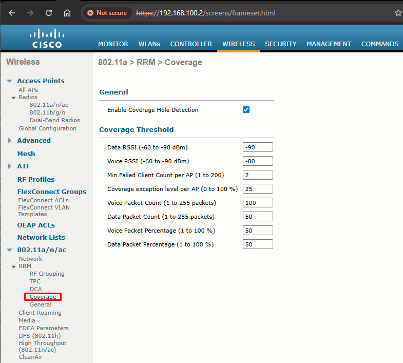
Step 2: Select the Enable Coverage Hole Detection check box to enable coverage hole detection, or unselect it to disable this feature. If you enable coverage hole detection, the controller automatically determines, based on data received from the access points, if any access points have clients that are potentially located in areas with poor coverage. The default value is Enabled.
Step 3: In the Data RSSI text box, enter the minimum RSSI value for data packets received by the AP. The value that you enter is used to identify coverage holes (or areas of poor coverage) within your network. If the AP receives a packet in the data queue with an RSSI value below the value that you enter here, a potential coverage hole has been detected. The valid range is –90 to –60 dBm, and the default value is –90 dBm. The AP takes data RSSI measurements every 5 seconds and reports them to the controller in 90-second intervals.
Step 4: In the Voice RSSI text box, enter the minimum RSSI value for voice packets received by the AP. The value that you enter is used to identify coverage holes within your network. If the AP receives a packet in the voice queue with an RSSI value below the value that you enter here, a potential coverage hole has been detected. The valid range is –90 to –60 dBm, and the default value is –75 dBm. The access point takes voice RSSI measurements every 5 seconds and reports them to the controller in 90-second intervals.
Step 5: In the Min Failed Client Count per AP text box, enter the minimum number of clients on an AP with an RSSI value at or below the data or voice RSSI threshold. The valid range is 1 to 75, and the default value is 3.
Step 6: In the Coverage Exception Level per AP text box, enter the percentage of clients on an AP that are experiencing a low signal level but cannot roam to another AP. The valid range is 0 to 100%, and the default value is 25%.
Step 7: Reenable the 802.11 networks that had been disabled at Step 0.
Task 6: Manual RF Configuration
You might sometimes want to keep RRM from changing the RF conditions in parts of your wireless network. For instance, you might have client devices that operate at a fixed transmit power level. Ideally, the AP and client power levels should be identical or matched. If RRM raises or lowers AP power levels at a later time, then asymmetric power levels would result.
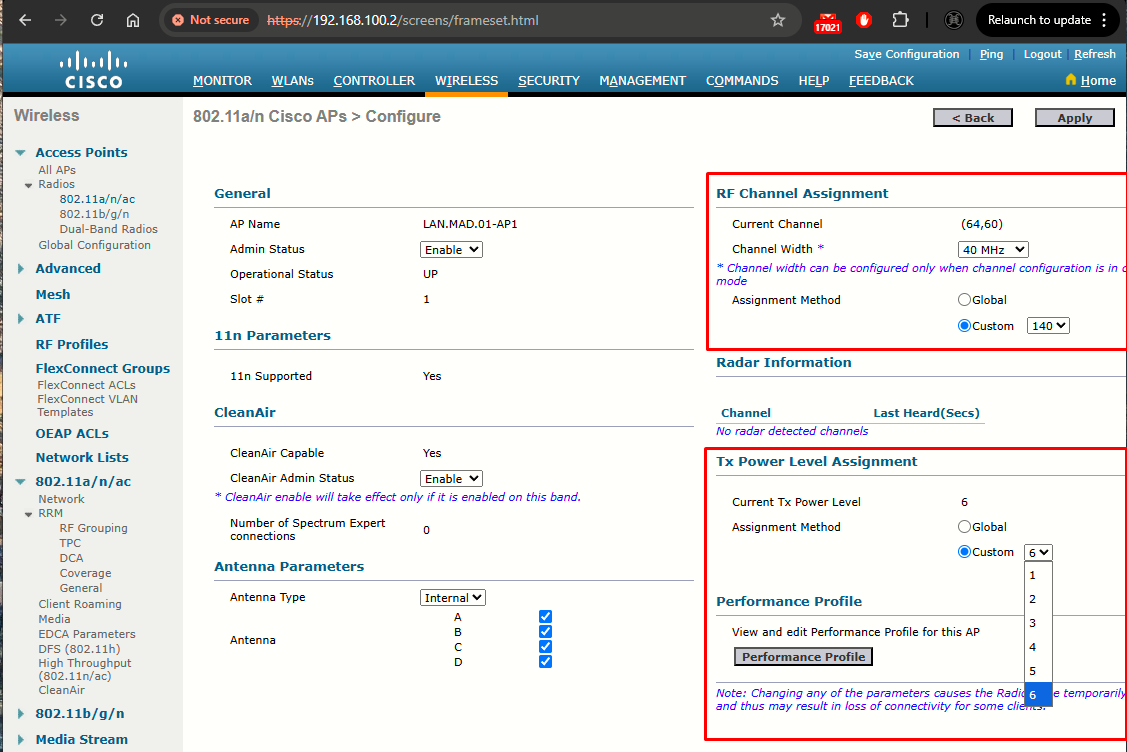
You can override RRM on a per-AP basis by selecting Wireless > Access Points > Radios > 802.11a/n/ac or 802.11b/g/n. From the list of APs displayed, choose a specific AP and select the drop-down menu at the far-right side of the list. From this menu, select Configure.
On the AP configuration page, you can set the channel under RF Channel Assignment or the transmit power under Tx Power Level Assignment. By default, the Global radio button is selected for each, which allows the value to be determined globally within the RF group. You can set a specific channel or power level by selecting the Custom radio button and then choosing a value from the drop-down list:
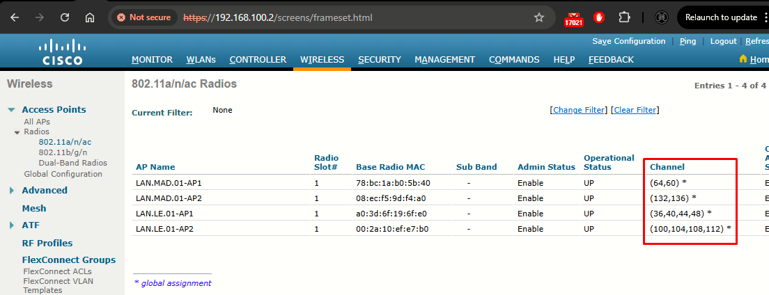
Task 7: Verifying RRM Results
The RRM algorithms can either run at regular intervals or on demand. You can display the channel number and transmit power level that are being used on every AP by selecting Wireless > Access Points > Radios > 802.11a/n/ac or 802.11b/g/n: