
Lab 4-6: Configuring SSO Redundancy
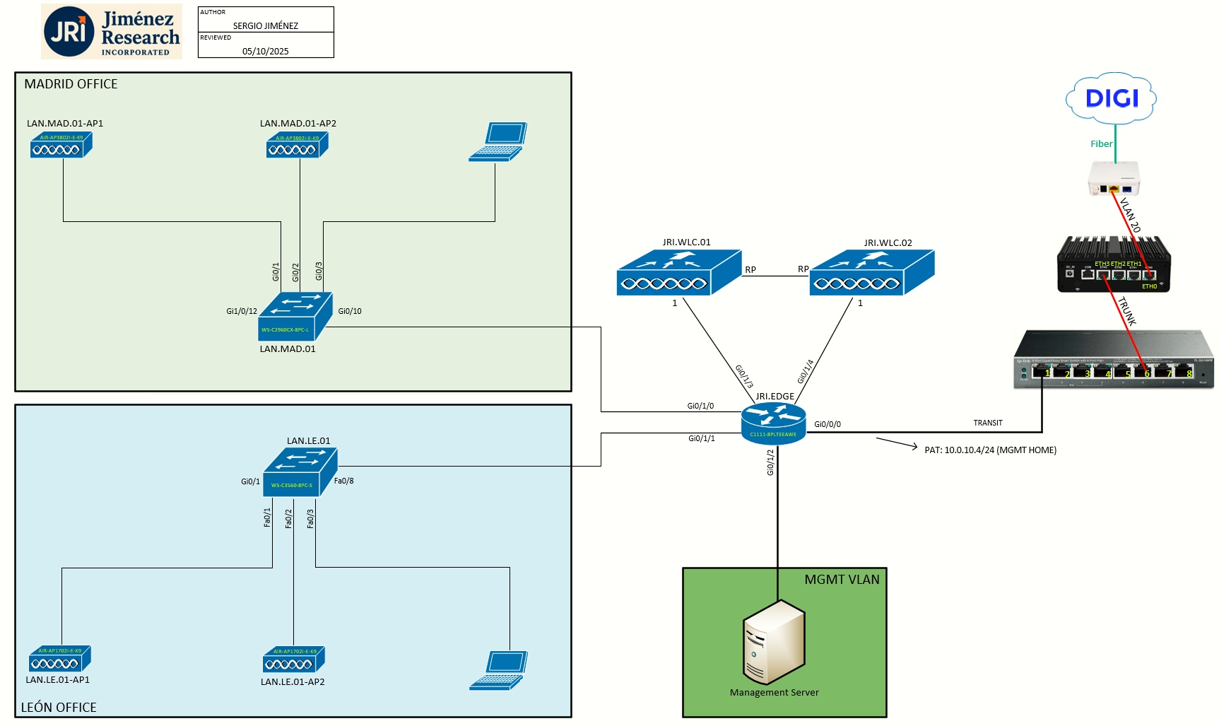
Topology
Task 1: Introduction to HA SSO
This guide provides information on the theory of operation and configuration for the Cisco Unified Wireless LAN Controller (WLC) as it pertains to supporting stateful switchover of access points and clients (AP and Client SSO).
The new High Availability (HA) feature (that is, AP SSO) set within the Cisco Unified Wireless Network software release version 8.0 and above allows the access point (AP) to establish a CAPWAP tunnel with the Active WLC and share a mirror copy of the AP database with the Standby WLC. The APs do not go into the Discovery state when the Active WLC fails and the Standby WLC takes over the network as the Active WLC.
There is only one CAPWAP tunnel maintained at a time between the APs and the WLC that is in an Active state. The overall goal for the addition of AP SSO support to the Cisco Unified Wireless LAN is to reduce major downtime in wireless networks due to failure conditions that may occur due to box failover or network failover.
To support High Availability without impacting service, there needs to be support for seamless transition of clients and APs from the active controller to the standby controller. Client SSO will be supported for clients which have already completed the authentication and DHCP phase and have started passing traffic. With Client SSO, a client's information is synced to the Standby WLC when the client associates to the WLC or the client’s parameters change. Fully authenticated clients, i.e. the ones in Run state, are synced to the Standby and thus, client re-association is avoided on switchover making the failover seamless for the APs as well as for the clients, resulting in zero client service downtime and no SSID outage.
Product / Feature Overview
- The new architecture for HA is for box-to-box redundancy. In other words, 1:1 where one WLC will be in an Active state and the second WLC will be in a Hot Standby state continuously monitoring the health of the Active WLC via a Redundant Port.
- Both the WLCs will share the same set of configurations including the IP address of the Management interface.
- The WLC in the Standby state does not need to be configured independently as the entire configuration will be synced from the Active WLC to the Standby WLC via a Redundant Port.
- The AP's CAPWAP State and a mirror copy of the AP database is maintained on the Standby WLC.
- The APs do not go into the Discovery state when the Active WLC fails and the Standby WLC takes over the network's Active WLC.
- There is no preempt functionality. When the previous Active WLC comes back, it will not take the role of the Active WLC, but will negotiate its state with the current Active WLC and transition to a Standby state.
- The Active and Standby decision is not an automated election process. The Active/Standby WLC is decided based on HA SKU.
- A WLC with HA SKU UDI will always be the Standby WLC for the first time when it boots and pairs up with a WLC running a permanent count license. For existing WLCs having a permanent count license, the Active/Standby decision can be made based on manual configuration.
Task 2: Introduction of New Interfaces for HA Interaction
Redundancy Management Interface (RMI)
The active and standby-hot controllers use the RMI to check the health of the peer controller and the default gateway of the management interface through network infrastructure.
The RMI is also used to send notifications from the active controller to the standby-hot controller if a failure or manual reset occurs. The standby-hot controller uses the RMI to communicate to the syslog, NTP/SNTP server, FTP, and TFTP server.
It is mandatory to configure the IP addresses of the Redundancy Management Interface and the Management Interface in the same subnet on both the primary and secondary controllers.
 Example configuration from Cisco.com
Redundancy Port
The redundancy port (RP) is used for configuration, operational data synchronization, and role negotiation between the primary and secondary controllers. It is also used in order to check peer reachability sending UDP keep-alive messages every 100 msec (default timer) from the Standby WLC to the Active WLC. Also, in the event of a box failure, the Active WLC will send notification to the Standby WLC via the RP
Task 3: Guidelines for HA SSO
- Don't pair two controllers of different hardware models. If they are paired, the higher controller model becomes the active controller and the other controller goes into maintenance mode.
- Don't pair two controllers on different controller software releases. If they are paired, the controller with the lower redundancy management address becomes the active controller and the other controller goes into maintenance mode.
-
If the controllers cannot reach each other through the redundant port and the RMI, the primary controller becomes active and the standby-hot controller goes into the maintenance mode.
-
It's recommended to enable LAG on the controllers before enabling the port channel in the infrastructure switches.
-
All the configurations that require reboot of the active controller results in the reboot of the standby-hot controller.
-
Client SSO related guidelines:
-
The standby controller maintains two client lists: one is a list of clients in the Run state and the other is a list of transient clients in all the other states.
-
Only the clients that are in the Run state are maintained during failover. Clients that are in transition, such as roaming, 802.1X key regeneration, web authentication logout, and so on, are dissociated.
-
As with AP SSO, Client SSO is supported only on WLANs. The controllers must be in the same subnet. Layer3 connection is not supported.
-
Task 4: Reworking the Topology to Accomodate HA SSO
You can see the topology above differs from the previous labs. We have moved the WLCs out of the regional branches scope, and connected them directly to JRI.EDGE. We will create a dedicated VLAN/subnet called WLC_MANAGEMENT:
| NETWORK | VLAN | SUBNET | GATEWAY | DHCP |
| WLC_MANAGEMENT | 100 | 192.168.100.0/24 | 192.168.100.1 | NO |
And on this subnet we'll make the following assignments:
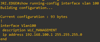
- JRI.EDGE will have the L3 interface: 192.168.100.1/24
- JRI.WLC.01 management: 192.168.100.2/24
- JRI.WLC.01 redundancy-management: 192.168.100.3/24
- JRI.WLC.02 management: 192.168.100.4/24
- JRI.WLC.02 redundancy-management: 192.168.100.5/24
Task 5: Configuring HA SSO (CLI)
Step 0: Disable LAG on JRI.WLC.02 - I tested LAG on this standalone WLC on a previous lab, but since I can't form L2 EtherChannel on the Cisco 1111 ISR, I will just disable it before continuing to make things easier. So, I just set LAG Mode on next reboot at Controller menu to Disabled, saved config, rebooted the WLC, and while it was rebooting I just deleted the port-channel interface on LAN.LE.01 and reverted the configuration on the port Gi0/1.
Step 1: Now, before configuring HA, it is mandatory to have both controller's management interface in the same subnet. I will make this change now according to the table above and once applied, I will cable both controllers accordingly.
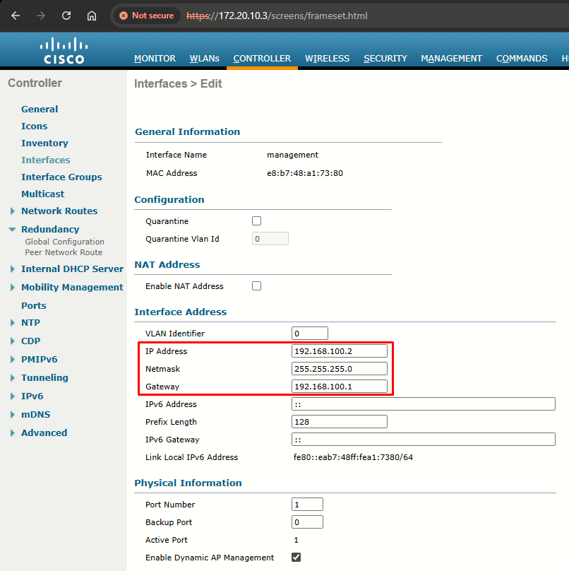
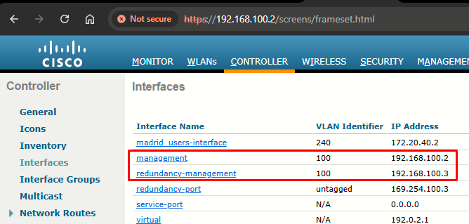
- Beginning with JRI.WLC.01, I'll go to Controller > Interfaces and clic on the management interface
- I will change IP Address, Netmask and Gateway according to the table above:
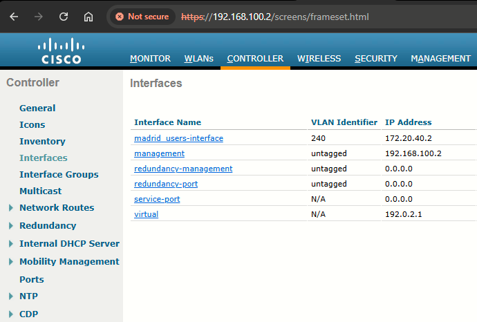
- After making this change I will physically swap out the fiber SFP I was using on Port 1, and insert a copper SFP on that port. Only after doing that will I be able to access the GUI again, this time at https://192.168.100.2/
- Also, I want to make sure LAG is enabled on JRI.WLC.01 (to match what is configured for JRI.WLC.02)
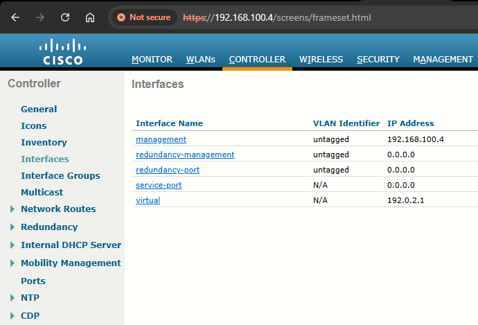
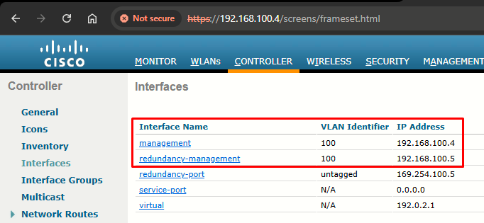
- I will repeat same steps for JRI.WLC.02 making sure the IP configured is 192.168.100.4
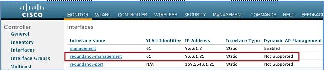
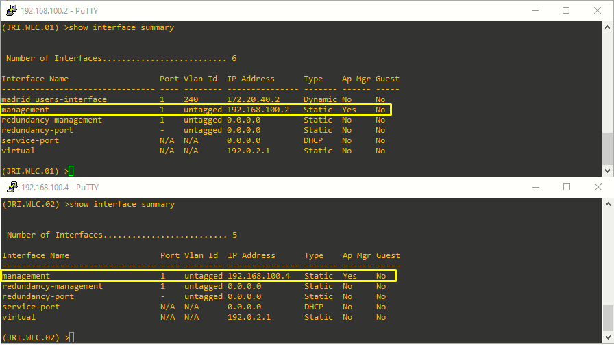
- If everything was done correctly, both WLCs should have the new management interface IPs (in the same subnet):

|
|
|
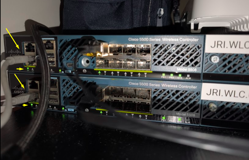
Step 2: Before enabling HA, ensure RP is up in both controllers. I will use a dedicated back-to-back connection.
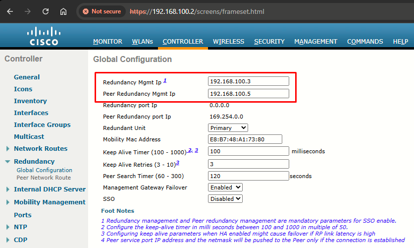
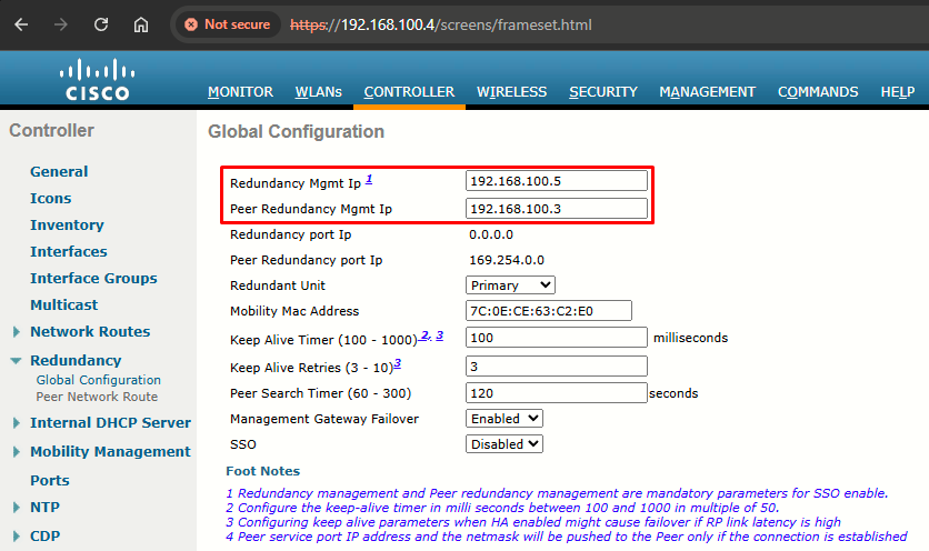
Step 3: HA is disabled by default. Before you enable HA, it is mandatory to configure the Redundancy Management IP Address and Peer Redundancy Management IP Address. Both the interfaces should be in the same subnet as the Management Interface:
| (JRI.WLC.01) >config interface address redundancy-management 192.168.100.3 peer-redundancy-management 192.198.100.5
|
(JRI.WLC.02) >config interface address redundancy-management 192.168.100.5 peer-redundancy-management 192.198.100.3
|
Step 4: Configure one WLC as Primary and the other WLC as Secondary from the Redundant Unit drop-down list.
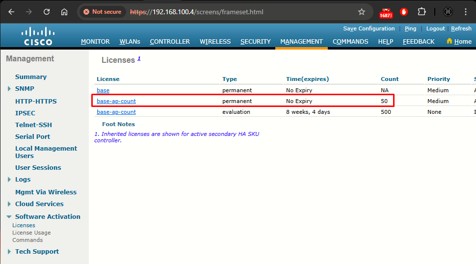
Please beware of my scenario (Management > Software Activation > Licenses):
|
|
|
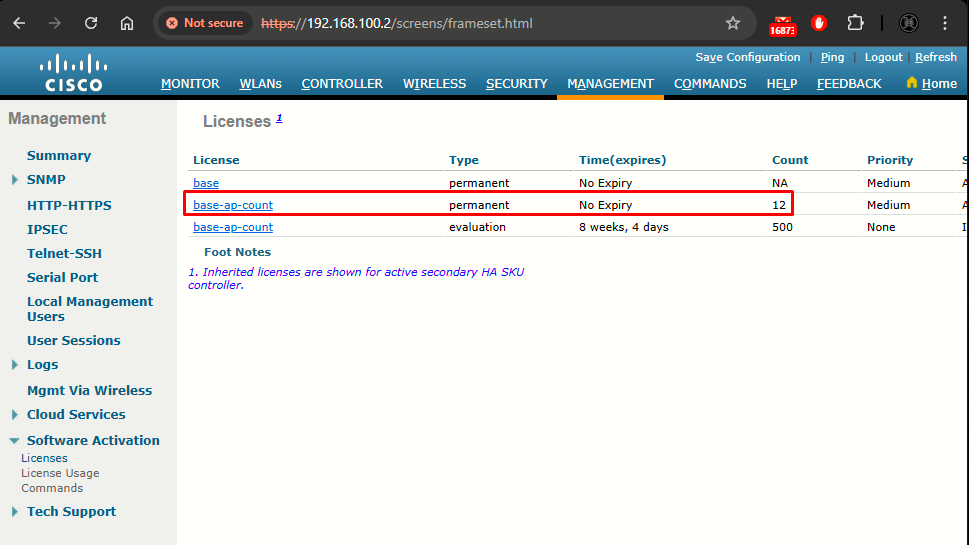
- JRI.WLC.01 has base-ap-count permanent license of 12 APs
- JRI.WLC.02 has base-ap-count permanent license of 50 APs
According to the HA Deployment Guide, there are some rules regarding Licensing for HA Pair. We are in the condition that Both the WLCs have a valid AP Count license. Now, on this condition, some rules must be followed:
- For 5508 WLCs, a minimum of 50 AP permanent license is needed to convert any unit to Standby.
- AP-count license information will be pushed from Active to Standby.
- The WLC configured as Secondary will not use its own installed license, and only the inherited license from the Active will be used.
Hence, JRI.WLC.02, which meets the 50 AP minimum license, will be the one converted to Standby.
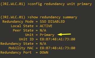
First, I will configure JRI.WLC.01 as the Primary unit:
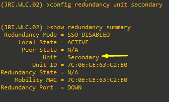
Then, JRI.WLC.02 is configured as secondary unit:
Step 5: After the WLCs are configured with Redundancy Management and Peer Redundancy Management IP Addresses and Redundant Units are configured, it is time to enable SSO. It is important to make sure that physical connections are up between both the controllers (that is, both the WLCs are connected back to back via the RP using an Ethernet cable) and the uplink is also connected to the infrastructure switch and the gateway is reachable from both the WLCs before SSO is enabled.
Once SSO is enabled, it will reboot the WLCs. While it boots, the WLCs negotiate the HA role as per the configuration via Redundant Port. If the WLCs cannot reach each other via Redundant Port or via the Redundant Management Interface, the WLC configured as Secondary may go in to Maintenance Mode.
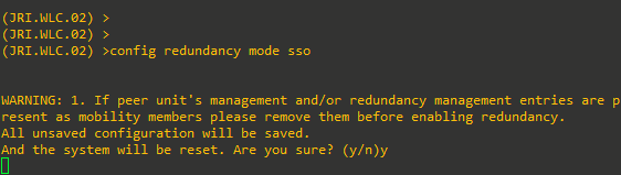
I will use the following CLI command to enable AP SSO. Enabling this will initiate a WLC reboot:
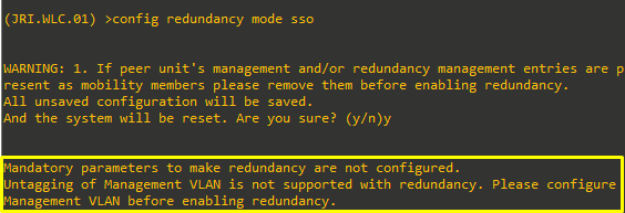
As you can see I got the following error:
Mandatory parameters to make redundancy are not configured.
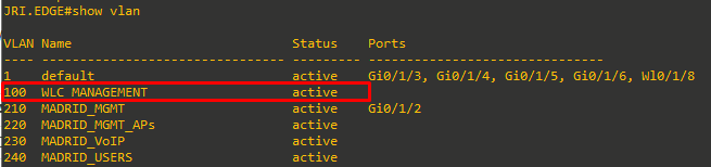
Untagging of Management VLAN is not supported with redundancy. Please configure Management VLAN before enabling redundancy.
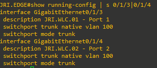
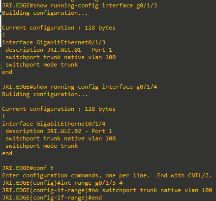
So I will just configure the WLC_MANAGEMENT VLAN on the management interface at both WLCs, and reconfigure the JRI.EDGE ports that connect to both removing the native VLAN configuration.
|
|
 |
VLAN change is automatically applied to redundancy-management interface when applied first to management interface.
Now it will work. We'll do the same on JRI.WLC.02. Configuration will be saved automatically and they will reboot automatically:
Step 6: As we saw in the previous step, enabling SSO will reboot the WLCs in order to negotiate the HA role as per the configuration performed. Once the role is determined, configuration is synced from the Active WLC to the Standby WLC via the RP. Initially, the WLC configured as Secondary will report XML mismatch and download the configuration from Active and reboot again. During the next reboot after role determination, it will validate the configuration again, report no XML mismatch, and process further in order to establish itself as the Standby WLC.
JRI.WLC.02 (NOW JRI.WLC.01-Standby) CONSOLE BOOTUP (AFTER ROLE DETERMINATION)
Validating...... OK
Set PLX switch MPS settings .............!!!!!!!
Starting DB Services...
Detecting Hardware ...
set smp_affinity for irq 48
003f
Starting Web Services ...
DP from CGE5.0 ...
starting pid 1209, tty '/dev/ttyS0': '/usr/bin/gettyOrMwar'
Starting NA Connector...
Setting up ZVM
Exporting LD_LIBRARY_PATH
Cryptographic library self-test....
Testing SHA1 Short Message 1
Testing SHA256 Short Message 1
Testing SHA384 Short Message 1
SHA1 POST PASSED
Testing HMAC SHA1 Short Message 1
Testing HMAC SHA2 Short Message 1
Testing HMAC SHA384 Short Message 1
passed!
XML config selected
XML config selected
Validating XML configuration
octeon_device_init: found 1 DPs
readCPUConfigData: cardid 0x6070001
Cisco is a trademark of Cisco Systems, Inc.
Software Copyright Cisco Systems, Inc. All rights reserved.
Cisco AireOS Version 8.5.182.109
Firmware Version FPGA 1.7, Env 1.8, USB console 2.2
Initializing OS Services: ok
Initializing Serial Services: ok
Initializing Network Services: ok
Initializing Licensing Services: ok
Starting Statistics Service: ok
License daemon start initialization.....
License daemon running.....
Starting Licensing Services: ok
Starting ARP Services: ok
Starting Trap Manager: ok
Starting Data Externalization services: ok
Starting Network Interface Management Services: ok
Starting System Services: ok
Starting FIPS Features: ok : Not enabled
Starting SNMP services: ok
Starting Fastpath Hardware Acceleration: ok
Starting Fastpath Console redirect : ok
Starting Fastpath DP Heartbeat : ok
Fastpath CPU0.00(0): Starting Fastpath Application. SDK-Cavium Networks Octeon SDK version 1.8.0, build 269. Flags-[DUTY CYCLE] : ok
Fastpath CPU0.00(0): Initializing last packet received queue. Num of cores(10)
Fastpath CPU0.00(0): Initializing Global Packet Queue. Num of packets supported(1)
Fastpath CPU0.00(0): Init MBUF size: 1856, Subsequent MBUF size: 2040
Fastpath CPU0.00(0): Core 0 Initialization and FIPS self-test: ok
Fastpath CPU0.00(0): 10 Cores are being initialized
Fastpath CPU0.00(0): Initializing Timer...
Fastpath CPU0.00(0): Initializing Timer...done.
Fastpath CPU0.00(0): Initializing Timer...
Fastpath CPU0.00(0): Initializing NBAR AGING Timer...done.
Fastpath CPU0.00(0): Received instruction to get link status
Fastpath CPU0.01(0): Core 1 Initialization and FIPS self-test: ok
Fastpath CPU0.02(0): Core 2 Initialization and FIPS self-test: ok
Fastpath CPU0.03(1): Core 3 Initialization and FIPS self-test: ok
Fastpath CPU0.04(2): Core 4 Initialization and FIPS self-test: ok
Fastpath CPU0.05(3): Core 5 Initialization and FIPS self-test: ok
Fastpath CPU0.06(4): Core 6 Initialization and FIPS self-test: ok
Fastpath CPU0.07(5): Core 7 Initialization and FIPS self-test: ok
Fastpath CPU0.08(6): Core 8 Initialization and FIPS self-test: ok
Fastpath CPU0.09(7): Core 9 Initialization and FIPS self-test: ok
Starting Switching Services: ok
Starting QoS Services: ok
Starting Policy Manager: ok
Starting Data Transport Link Layer: ok
Starting Access Control List Services: ok
Starting System Interfaces: ok
Starting Client Troubleshooting Service: ok
Starting Certificate Database: Initializing Curl Globally..
ok
Starting VPN Services: ok
Starting Management Frame Protection: ok
Starting DNS Services: ok
ok
Starting Redundancy: Starting Peer Search Timer of 120 seconds
Initiate Role Negotiation Message to peer
Found the Peer. Starting Role Determination...ok
Start rmgrPingTask: ok
Starting LWAPP: ok
Starting CAPWAP: ok
Starting LOCP: ok
Starting Security Services: ok
Starting OpenDNS Services: ok
Starting Policy Manager: ok
Starting Authentication Engine: ok
Starting Mobility Management: ok
Starting Capwap Ping Component: ok
Starting AVC Services: ok
Starting AVC Flex Services: ok
Starting Virtual AP Services: ok
Starting AireWave Director: ok
Starting Network Time Services: ok
Starting Cisco Discovery Protocol: ok
Starting Broadcast Services: ok
Starting Logging Services: ok
Starting DHCP Server: ok
Starting IDS Signature Manager: ok
Starting RFID Tag Tracking: ok
Starting RF Profiles: ok
Starting Power Supply and Fan Status Monitoring Service: ok
Starting Mesh Services: ok
Starting TSM: ok
Starting CIDS Services: ok
Starting Ethernet-over-IP: ok
Starting DTLS server: enabled in CAPWAP
Starting CleanAir: ok
Starting WIPS: ok
Starting SSHPM LSC PROV LIST: ok
Starting RRC Services: ok
Starting SXP Services: ok
Starting Alarm Services: ok
Starting FMC HS: ok
Starting IPv6 Services: ok
Starting Config Sync Manager : ok
Starting Hotspot Services: ok
Starting Tunnel Services New: ok
Starting PMIP Services: ok
Starting Portal Server Services: ok
Starting mDNS Services: ok
Starting Management Services:
Web Server: CLI: Secure Web: ok
Starting IPSec Profiles component: ok
Starting CPU ACL Logging services: ok
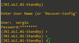
(JRI.WLC.01-Standby)
Enter User Name (or 'Recover-Config' this one-time only to reset configuration to factory defaults)
User:Once SSO is enabled, the Standby WLC can be accessed via console connection or via SSH on the service port and on the redundant management interface.
Step 7: After SSO is enable, WLC is rebooted and the XML configuration is synced, JRI.WLC.01 will transition its state to Active and JRI.WLC.02 will transition its state to Standby HOT. From this point onwards, GUI/SSH for JRI.WLC.02 on the management interface will not work, as all the configurations and management should be done from the Active WLC. If required, the Standby WLC (JRI.WLC.02) can be managed via the Console or SP (as stated on the note above). Also, once the Peer WLC transitions to the Standby Hot state, -Standby keyword is automatically appended to the Standby WLCs prompt name.
Task 6: Verifying SSO
Complete these steps in order to check redundancy state:
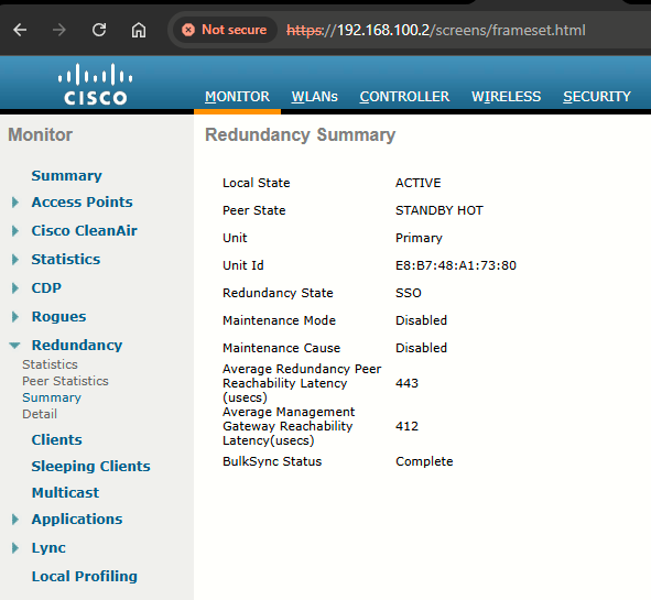
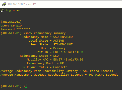
Step 1: For JRI.WLC.01 (Active), go to Monitor > Redundancy > Summary:
For JRI.WLC.02 (JRI.WLC.01-Standby onwards), from a console connection:
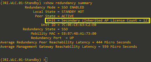
See how it has inherited the 12 AP count license from the JRI.WLC.01 WLC.
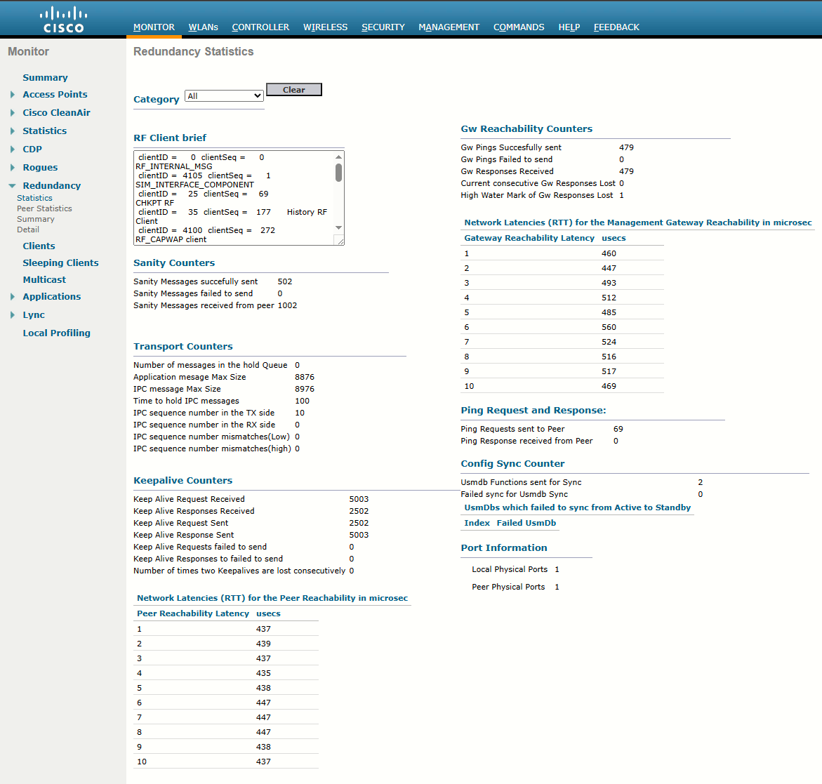
Task 7: Monitoring HA Redundancy
We have many counters available at Monitor > Redundancy > Statistics. This will show counters from Active WLC side:
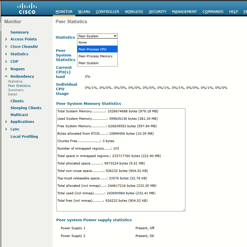
We also have Peer Statistics under Redundancy submenu. Here we can select from drop-down:
- Peer-Process CPU
- Peer-Process Memory
- Peer-System
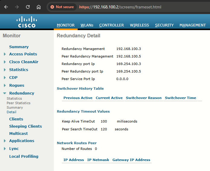
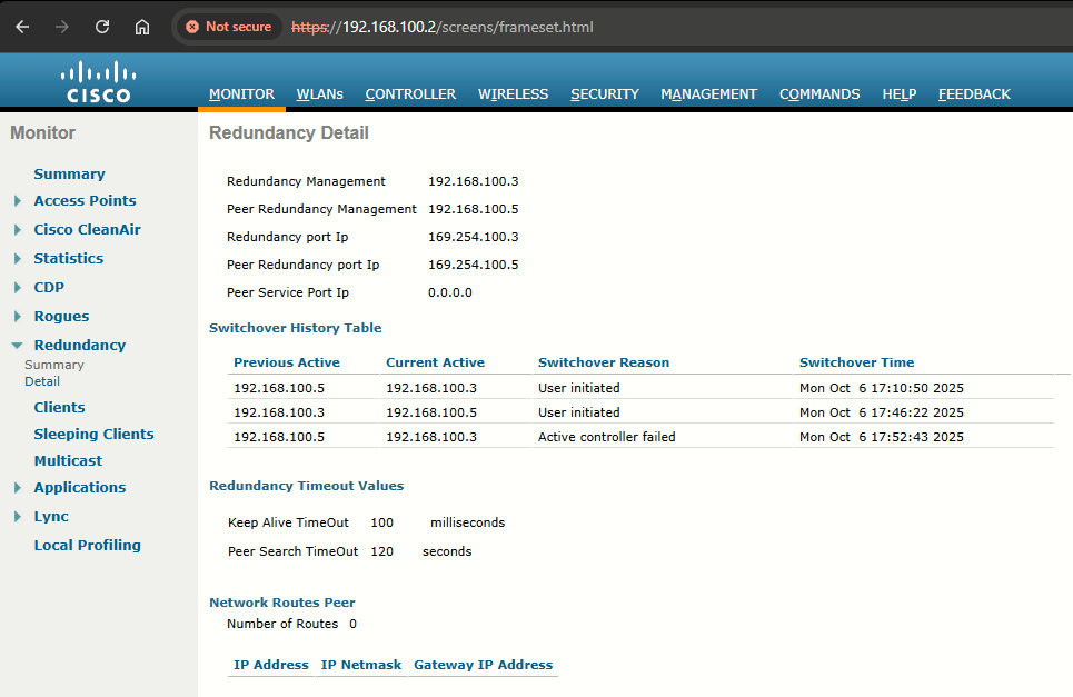
Finally, the Detail page, also under Redundancy, have also some handy info:
Task 8: Re-Joining APs to the New HA SSO Pair
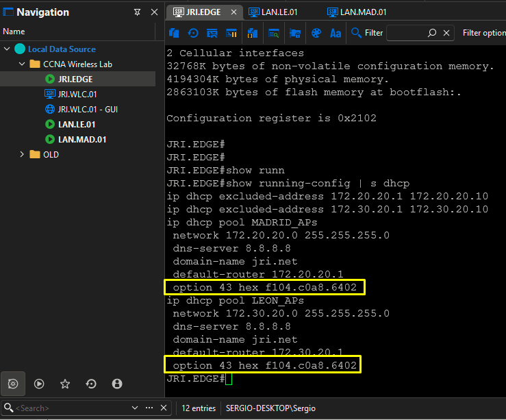
Management interface has changed its AP since previous lab. So the option 43 should be updated to reflect this change. We will include only the management IP of the Active WLC -> 192.168.100.2
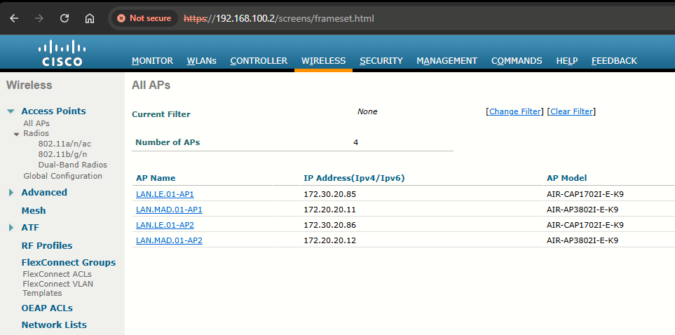
After rebooting the APs, I can see how they joined the WLC:
Task 9: Failover Process in the HA Setup
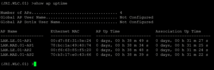
In the HA setup, the AP's CAPWAP state is maintained on the Active WLC as well as the Standby WLC (only for APs which are in a Run state). That is, Up Time and Association Up Time is maintained on both the WLC, and when switchover is initiated, the Standby WLC takes over the network.
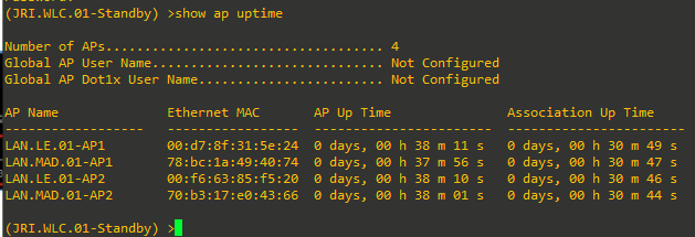
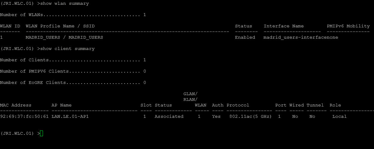
For this example, JRI.WLC.01 is in an Active state and serving the network, and JRI.WLC.02 is in a Standby state monitoring the Active WLC. Although JRI.WLC.02 is in Standby state, it still maintains the CAPWAP state of the AP:
Task 10: Simulate Box Failover
Step 1: I have configured a WLAN and joined my smartphone to it:
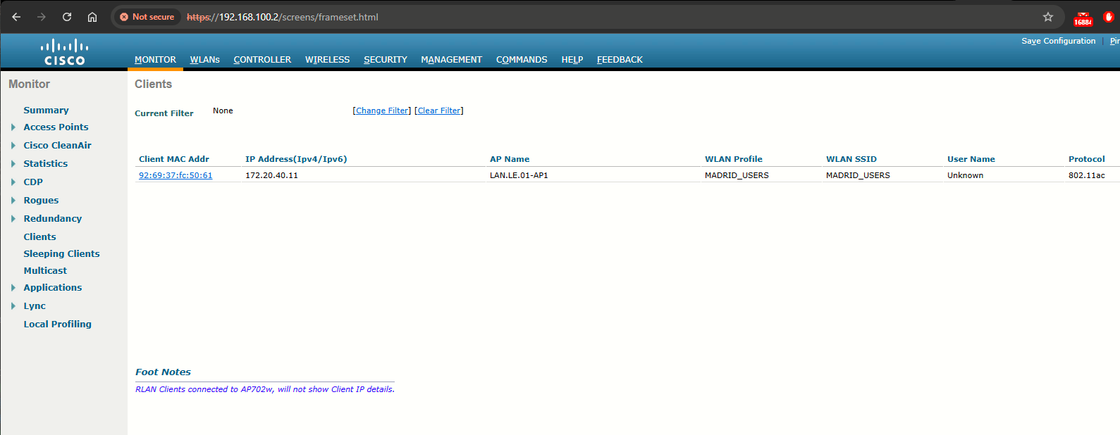
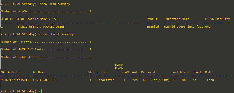
Step 2: The client database is not synced on the Standby WLC, so the client entry will not be present on the Standby WLC. Once the WLAN is created on the Active WLC, it will also be synced to the Standby WLC via the RP:
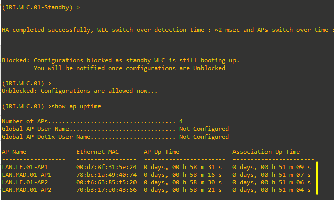
Step 3: Issue the redundancy force-switchover command on the Active WLC. This command will trigger a manual switchover where the Active WLC will reboot and the Standby WLC will take over the network. In this case, the client on the Active WLC will be de-authenticated and join back on the new Active WLC.
From the output via console of JRI.WLC.02 (the previous standby), notice how the prompt changes. See also how AP UP Time as well as Association Up Time is maintained, and the APs did not go into the discovery state:
Some Final Adjustments
Below, two parameters have been adjusted:
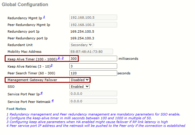
I was getting Standby IPC Failure on the console on the standby WLC when switching off the active one.
To resolve that during the SSO failover process, I changed two critical parameters in the Redundancy Global Configuration. First, I disabled the Management Gateway Failover. This prevents the standby controller from rebooting if it cannot ping the default gateway during the transition, ensuring that the standby unit assumes the active role based solely on the health of its peer rather than external network reachability.
Secondly, I increased the Keep Alive Timer from 100ms to 300ms. The original 100ms setting was too aggressive for physical 5508 hardware, causing the standby unit to interpret minor latency spikes during the primary unit's shutdown as a catastrophic communication failure. By relaxing this timer and disabling the gateway check, I have created a more resilient failover environment that allows the standby controller to transition to the active state smoothly without triggering a panic-induced reboot.
Sources
High Availability (SSO) Deployment Guide
https://www.cisco.com/c/en/us/td/docs/wireless/controller/technotes/8-7/High_Availability_DG.html#pgfId-43710
Cisco Wireless Controller Configuration Guide, Release 8.5, Chapter: High Availability
https://www.cisco.com/c/en/us/td/docs/wireless/controller/8-5/config-guide/b_cg85/high_availability.html