
Configuring OPNsense Network Interfaces
Introduction
Starting from where we left on the previous page, where we configured the Proxmox network interfaces, we will now configure the interfaces on the OPNsense VM.
First, I will configure the WAN interface and the PPPoE session. Then I will configure the VLANs needed according to the addressing plan (more below).
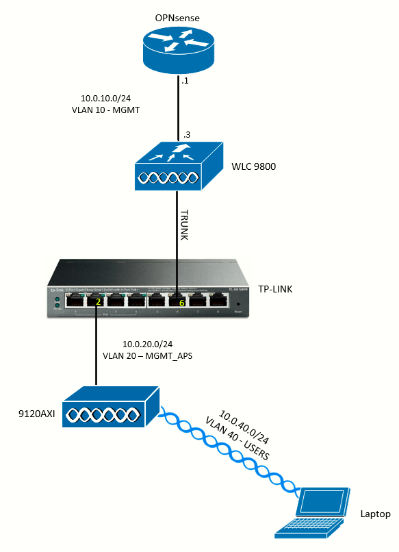
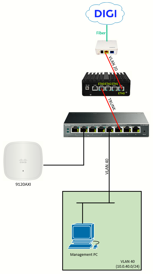
The topology used, for reference:
|
|
|
Accessing the OPNsense GUI
With the temporary dedicated management interface IP set, I go to https://<IP>/ to access the OPNsense GUI.
WAN Interface (PPPoE)
To configure the PPPoE device, go to Interfaces > Devices > Point-to-Point, and add a device (+ symbol):
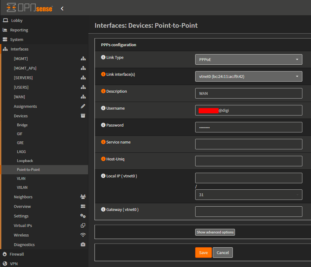
Fields to configure:
- Link Type: PPPoE
- Link interface(s): vtnet0 (the
waninterface on Proxmox) - Description: WAN
- Username: PPPoE DIGI username
- Password: PPPoE DIGI password
- MTU: usually no need to configure it, but should be set to 1492
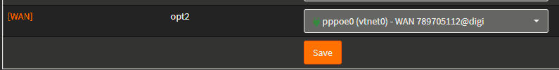
Once PPPoE is configured, go to Interfaces > Assignments, select from the dropdown of available interfaces pppoe (vtnet0). This will add the interface:
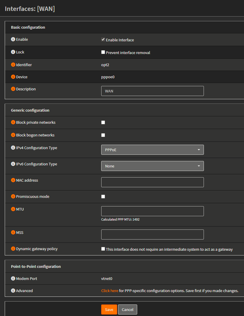
If we click on the interface we will enter that interface's configuration page, where we want to make sure the Enable Interface checkbox is enabled and that IPv4 Configuration Type is set to PPPoE:
LAN Interface (Trunk)
Recalling the addressing plan from the previous page, I will now configure the L3 interfaces on the OPNsense:
| NETWORK | ADDRESS |
| VLAN 10 (MGMT) | 10.0.10.0/24 |
| VLAN 20 (MGMT_APs) | 10.0.20.0/24 |
| VLAN 30 (SERVERS) | 10.0.30.0/24 |
| VLAN 40 (USERS) | 10.0.40.0/24 |
Start with the creation of the VLANs at Interfaces > Devices > VLAN:
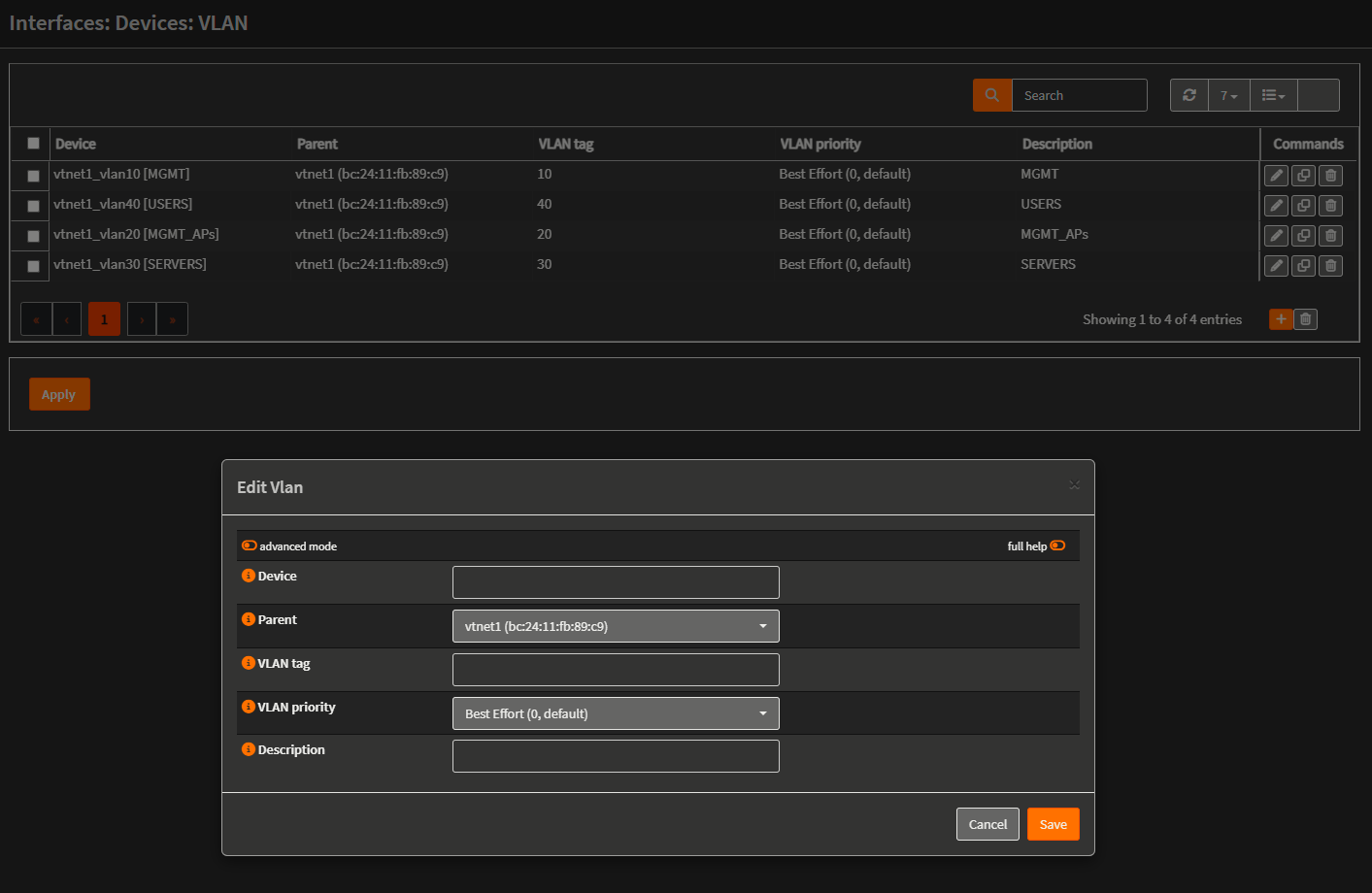
What I did is basically enter the device name in an standard accepted format <parent_interface>_vlan<tag> associate it to the parent interface and enter a simple name as description for easy identification later.
Then, back at the Interfaces > Assignment tab, I created the L3 interfaces:
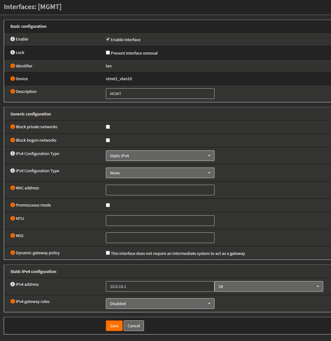
I did this for the three VLANs. Enabled the interfaces (checkbox), selected Static IPv4 and configured the interface address below.
Explanation
The OPNsense VM sees vtnet1 as its "LAN NIC". Because Proxmox isn't stripping tags, all the VLAN-tagged frames from the TP-LINK switch arrive at OPNsense exactly as they left the switch. Inside OPNsense we have created VLAN interfaces on top of vtnet1. Each VLAN interface is like a separate virtual NIC inside OPNsense. By assigning IP addresses it's like we're doing ROAS (router-on-a-stick). OPNsense becomes the default gateway for each VLAN. Since each VLAN is its own interface in OPNsense, we will then apply firewall policies independently, deciding which VLANs can talk to each other or to the WAN.
Modifying Firewall Rules
After assigning the interfaces, the networks are created in OPNsense but the devices in them will not be able to comunicate since there are no permit rules at the firewall. To edit this, go to Firewall > Rules > NETWORK_NAME
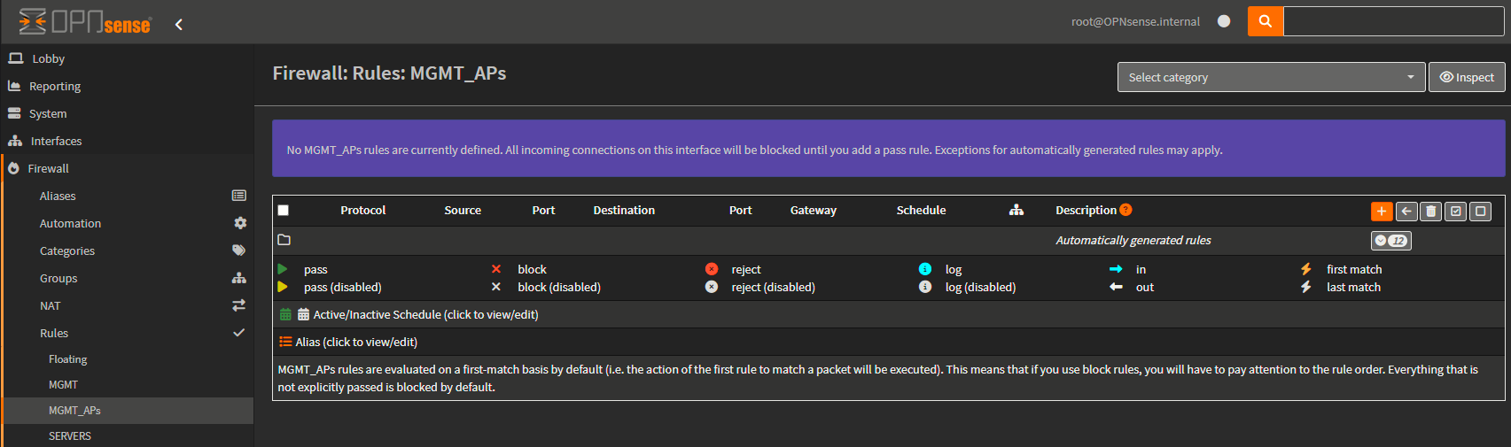
As we can see, there are no rules defined. All incoming connections on this interface will be blocked until you add a pass rule. Exceptions for automatically generated rules may apply.
To add rule, click the ( + ) symbol:
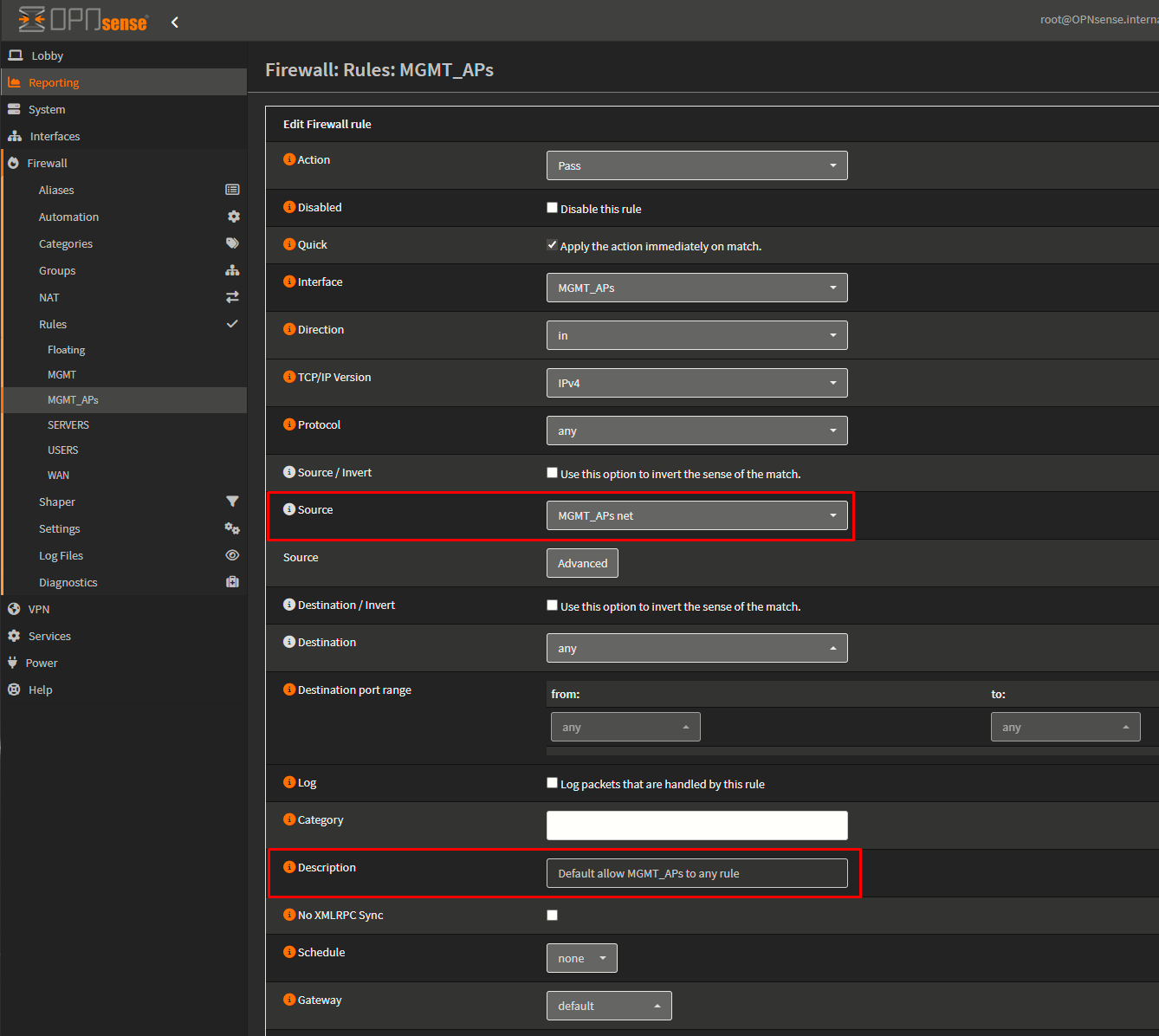
I will leave everything as default, but changing source to MGMT_APs net, and adding a description to the rule. Then I will add another rule for IPv6. Finally, Apply Changes.
Selecting the net itself as the source we are defining a rule to allow incoming traffic on the firewall, on the MGMT_APs interface (or VLAN) from this network. Without the rule, traffic coming from the MGMT_APs to the firewall will be denied.