
Configuring a modem on the AUX port of a Cisco router for EXEC dial-in connectivity
Introduction
In many situations, it would be necessary to allow a router to accept interactive command processor of Cisco IOS (EXEC) calls with a modem connected to the auxiliary (AUX) port of the router (out-of-band connection).
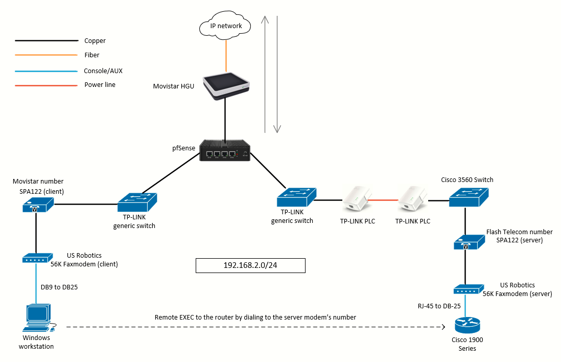 The topology used on this lab
The following device tag conventions are used on the topology:
- Client modem: the modem connected to the client ATA and Windows workstation that will initiate the call (dial-in) to the router.
- Server modem: the modem connected to server ATA and the Cisco router AUX port accepting incoming EXEC dial-in calls to the CLI.
Both client modem and server modem models are USR5630B.
The purpose of this lab is to initiate a connection from the client modem on the Windows workstation PC (using PuTTY) to the server modem, which will allow us access to the CLI of the Cisco router connected to the server modem.
Previous steps required
I will be using the topology just shown. All the devices are physical devices, there are no virtual machines involved in this lab. To make that topology work I had to:
- Setup the client modem on the Windows workstation
- Configure the pfSense / HGU connection in order to make the calling via the SPA122 ATAs work [Part 1] [Part 2] [Part 3]
- Buy a SIP number from Flash Telecom (SIP provider) and configure it on the SPA122
Additional recommended reading:
-
US Robotics 56K Faxmodem installation on Windows 98 (drivers + ControlCenter)
-
Advanced US Robotics 56K modem configuration via AT commands
Step 1: Cabling the server modem to the Cisco router
The router used in this lab is a Cisco 1921 with the following back connections:
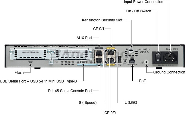
As we can see, the AUX port end on the router is an RJ-45 female connector. The other end (the port on the US Robotics modem is a DB-25 port) so we will need an RJ-45 to DB-25 cable like the 72-3663-01 Rev. B1 which is the one I will be using:
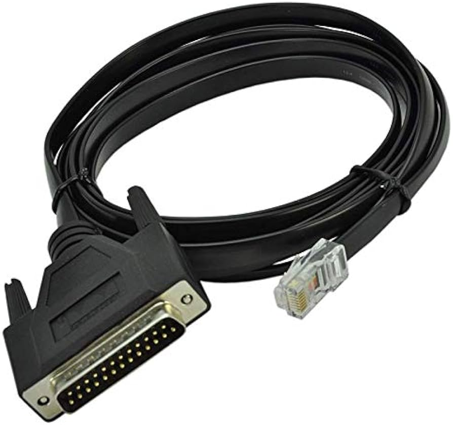 CAB-72-3663-01 Rev. B1
The CAB-72-3663-01 was a newer type of cable that replaced the old way of connecting the router to the server modem: a rolled-over RJ-45 to RJ-45 cable connected to an RJ-45 to DB-25 adapter. The CAB-72-3663-01 itself was replaced by CAB-CONAUX=.
The connection will look like this (on the left you can see the drawings from the Cisco docs, and on the right the actual connection on my lab):
|
|
|

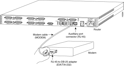

Note how there is no need for an RJ-45 to DB-25 adapter and thus it is not shown on the actual lab connection, just the 72-3663-01 Rev. B1 cable.
Step 2: Cabling the client and server modems to their respective ATA
For this step, we are assuming the ATAs are configured and working after going through the tutorials linked in the introduction of this page.
On my lab, I have two Spanish phone numbers ("números fijos") available. One of them will be configured on the client ATA, while the other will be configured on the server ATA as follows:
- Number from my ISP (Movistar/O2): configured on the client ATA
- Number from Flash Telecom: configured on the server ATA
The ATAs have two connections:
- From the ATA to the modem via an RJ-11 telephony cable (connected on the Phone 1 port of the ATA)
- From the ATA to the network (to a switch) via an RJ-45 patch cable (connected on the WAN port of the ATA)
Step 3: Introduction to the the router's AUX line
After we have set-up the topology, we are ready to configure the router. At this point, the server ATA must be up and configured. The server modem must be up and configured, and must be connected to the server ATA and to the router AUX port.
We are assuming a default configuration on the Cisco 1900 Series router (as if it was previously factory reset). After powering on the router, we can issue the command show line to verify if the modem is being detected:
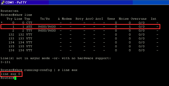
Note how the modem is detected at line 1 (AUX line). We can issue the command show line aux 0 or show line 1 to get more information about the AUX line (both commands are accepted by the Cisco 1921; the output is the same on both):

We can reverse telnet to the modem if we want to configure something on it (reverse telnet is explained here):

Also, we can enable debug commands related to the modem operation. This is done with the command debug modem:
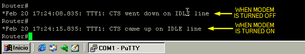
Note how the debug messages come from the TTY1 line which happens to be the AUX line (check images above).
Step 4: Configuring the router's AUX line
It is essential that you configure the TTY line before you configure or initialize the modem itself. The two main reasons are:
· In order to allow reverse Telnet access to the modem.
· If you change the line speed after the modem is initialized, the modem no longer communicates with the router until it is again told at what speed to talk to the router.
We are ready to begin configuring the AUX line to make it to work with a dial-up modem and to accept incoming calls to the CLI. We will examine each command configured under the AUX line separately:
First of all, enter the line configuration mode:
Router#conf t
Router(config)#line aux 0
Router(config-line)#
Under line config mode we will enter these commands:
| login | Use the password configured on the line to authenticate incoming connections. |
| password pass | The router uses this password (cisco) to authenticate incoming calls. |
| speed 115200 | Line speed to be used to communicate with the modem. Verify that the AUX port supports this speed. It's important to remember that this is the speed between the router and the modem. The actual dial session will have a much lower net speed, likely less thank 56Kbps. However, it's a good idea to make the line speed as fast as the modem can support. This will ensure that you get the best possible speed. Note that the default speed here is only 9600 bits or 9,6Kbps (if you don't increase this value, you will not be able to get the full advantage of the compression capabilities of modern modems). |
| transport input all | Allow all protocols to use the line. Needed also for reverse telnet to the modem. |
| modem inout | Configures the router to allow access to the modem, and vice versa. Basically, allows both incoming and outgoing connections to the modem. This command enables reverse telnet. Drop connection on loss of data carrier detect (DCD). Cycle DTR for connection close. |
| flowcontrol hardware | Enables RTS/CTS flow control. |
| stopbits 1 | Improve throughput by reducing async framing overhead (default is stopbits 2). |
If the router does not have an enable secret password, incoming connections will not be able to enter the enable mode. To allow incoming calls to enter enable mode, use the enable secret password command to setup the enable secret password.
Step 5: Configuring the server modem
The following instructions are for the U.S Robotics 56K Faxmodem (external). There is an image of this dial-up modem model above. The instructions for other make/model of modem may differ to the instructions below.
For most applications (not just dial-in to a router), configure a modern modem as this list details:
-
Reset to factory defaults (use a hardware flow control template if possible).
-
Use hardware (RTS/CTS) flow control.
-
Use normal modem control (hang up on DTR drop; drop DCD on carrier drop).
-
Enable, but do not require, error control (LAP-M [V.42] and MNP).
-
Enable, but do not require, data compression (V.42bis).
-
Enable all modulations supported by the modem.
-
Lock DTE speed at the highest rate supported by both the modem and the async line.
-
Enable autoanswer if needed. When you are in autoanswer mode, ignore the escape sequence (+++).
However, there is no need to explain every point on the list. On a U.S Robotics 56K Faxmodem we just need the router to apply the following initialization string on the modem: &F1S0=1
&F1 applies factory hardware flow control defaults, and S0=1 enables autoanswer on the first ring. In addition to that initialization string, 3Com/USR modems require DIP switches to be properly set. Since the are no DIP switches on this modem model (USR5630B) there is no need to configure anything else apart from the init string.
Modemcaps
Cisco IOS can issue initialization strings automatically, in a file called a modemcap, for most types of modems externally attached to the router. A modemcap is a series of parameter settings that are sent to the modem to configure it to interact with the Cisco router in a specified way. The Cisco IOS software defines modemcaps that have been found to properly initialize most modems so that they function properly with Cisco routers and access servers. This can be shown with the command show modemcap:
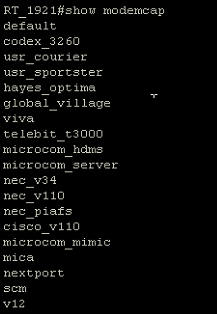 Pre-defined modemcaps on a Cisco 1921 router
We can expand the modemcaps' settings:
 Modemcap values for the "default" modemcap
Cisco IOS has an interesting feature called Modem Autoconfigure Discovery Feature. Basically, when applied to a line (i.e. the AUX line), it detects the type of modem attached and matches it to one of the pre-defined modemcaps, applying that modemcap configuration to the modem.
I have tried to use this feature it on this lab, and the USR5630B model is detected as the "default" type, whose modemcap settings do not fit for what we need:
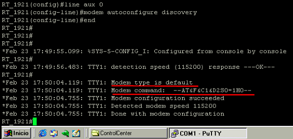 Modem autoconfigure discovery results when applied to the AUX line with a USR5630B modem attached to it
As we can see on the last image, the modem type detected is "default" and so, the init string configured in the "default" modemcap is applied as AT&F&C1&D2S0=1H0. As I explained before (and as it appears on Cisco docs), the proper init string for a U.S Robotics modem is AT&F1S0=1.
To get the red-highlighted messages on the image above, I had previously enabled the debug confmodem command. This debug displays information associated with the discovery and configuration of the modem attached to the router.
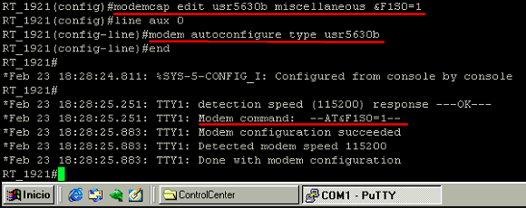
It is possible to create a custom modemcap and apply it to the AUX line. In fact, Cisco recommends the usage of the modem autoconfigure type <modemcap_name> command to configure modems attached to async lines:
- Use the modemcap edit command to define your own modemcap entry
Router(config)# modemcap edit usr5630b miscellaneous &F1S0=1On the line above, usr5630b is a user-defined parameter. This is the modemcap name.
- Apply the modemcap to the modem line (AUX line):
Router# configure terminal
Enter configuration commands, one per line.  End with CNTL/Z.
Router(config)# line aux 0
Router(config-line)# modem autoconfigure type usr5630b
Router(config-line)#
The most important thing to note here, is that we have applied the proper init string for this modem model using the miscellaneous section of the modemcap as indicated on the command reference:
modemcap edit <modemcap_name> miscellaneous <initialization string>The output of the debug that follows the implementation of our custom modemcap on the AUX line shows the modem is configured with the proper init string:
Step 6: Testing and verification
After configuring the AUX line and the modem init string, we are ready to test the dial-in to the router from the client modem (from the Windows workstation in the topology).
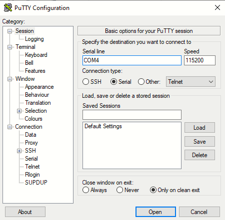
I will use PuTTY to access the modem terminal on the COM4 port at a DTE speed of 115200:
To initiate a call to the router I will issue the command ATDTxxxxxxx. DT stands for dial tone and is followed by the number configured on the remote modem:
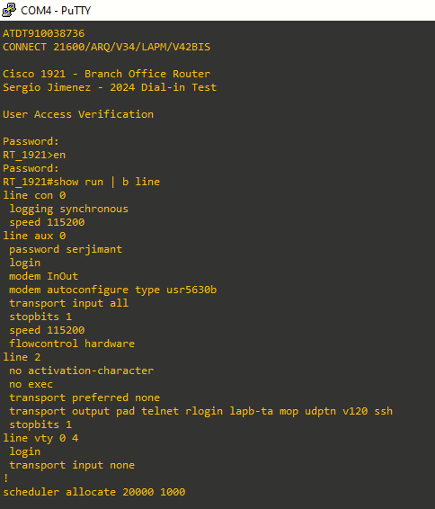
You can see we have gained access to the CLI by calling to the server modem number.
Sources:
Modem over VoIP
https://en.wikipedia.org/wiki/Modem_over_VoIP
Configuring a Modem on the AUX Port for EXEC Dialin Connectivity - Cisco
https://www.cisco.com/c/en/us/support/docs/dial-access/asynchronous-connections/10318-mod-aux-exec.html
Modem-Router Connection Guide
https://www.cisco.com/c/en/us/support/docs/dial-access/asynchronous-connections/17719-9.html
Attaching a US Robotics Modem to the Console Port of a Cisco Router (future lab)
https://www.cisco.com/c/en/us/support/docs/dial-access/asynchronous-connections/6320-50.html#miscellaneous
Configuring and Managing External Modems
https://www.cisco.com/en/US/docs/ios/dial/configuration/guide/dia_cfg_ext_modems_external_docbase_0900e4b18060bbb7_4container_external_docbase_0900e4b1823fb15d.html#wp1042562
Qué es DTR y cómo funciona en la comunicación de datos con un módem
https://polaridad.es/que-es-dtr-y-como-funciona-en-la-comunicacion-de-datos-con-un-modem/
56K Faxmodem User's Guide and Reference - Technical Reference
https://support.usr.com/support/5630b/5630b-ug/five.html