
Some theory on Ethernet straight-through and crossover cabling for 10BASE-T, 100BASE-TX and 1000BASE-T
A general introduction on Ethernet straight-through and crossover cables
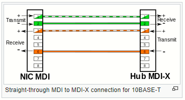
- In an Ethernet straight-through cable, pins on one end correspond exactly to the corresponding pins on the other end (pin 1 to pin 1, pin 2 to pin 2, etc.). Using the same wiring scheme at each end yields a straight-through cable (a given color wire connects to a given number pin, the same at both ends). In this case, the terminations are identical, so only one pinout is required. An straight-through in the context of Ethernet cabling, is a patch cable, defined as an electrical or optical cable used to connect ("patch in") one electronic or optical device to another for signal routing. Devices of different types (e.g., switch-computer, switch-router) are connected with patch cords. Patch cords are usually produced
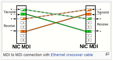
- In a crossover cable, pins do not correspond – some or all of the conductors are swapped at the terminations. For example, if pin 1 on one end goes to pin 2 on the other end, then pin 2 on one end goes to pin 1 on the other end, and the other pins remain unaffected. Such crossover cables are electrically symmetrical, meaning that they work identically regardless of which way you plug them in (if you turn the cable around, it still connects the same pins as before). Using different wiring at each end yields a crossover cable (a given color wire connects to one number pin at one end, and a different number pin at the other). An Ethernet crossover cable is used to connect computing devices of the same together directly. Intentionally crossed wiring in the crossover cable connects the transmit signals at one end to the receive signals at the other end.
Ethernet over twisted pair
Ethernet over twisted-pair technologies use twisted-pair cables for the physical layer of an Ethernet computer network. They are a subset of all Ethernet physical layers.
Early Ethernet used various grades of coaxial cable, but in 1984, StarLAN showed the potential of simple UTP. This led to the development of 10BASE-T and its successors 100BASE-TX, 1000BASE-T and 10GBASE-T.
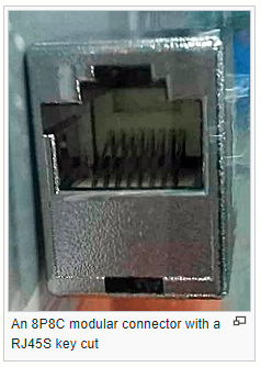
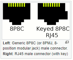
This standards use 8P8C modular connectors (often incorrectly called "RJ45" in this context), and supported cable standards range from Cat3 to Cat8. These cables typically have 4 pairs of wires for each connection, although early Ethernet used only 2 pairs.

El término RJ45 no es correcto para referirse a lo que normalmente se llama RJ45 plug (male) y RJ45 jack o socket (female). RJ45 originally referred to a specific wiring configuration of an 8P8C connector using a key that excluded the insertion in an un-keyed 8P8C socket. The standard un-keyed modular connectors became ubiquitous for computer networking and informally inherited the name RJ45.
Although 10BASE-T is rarely used as a normal-operation signaling rate today, it is still in wide use with network interface controller in Wake-on-LAN power-down mode and for special, low-power, low-bandwidth applications. 10BASE-T is still supported on most twisted-pair Ethernet ports with up to Gigabit Ethernet speed.
Ethernet over twisted pair cabling
Most Ethernet cables are wired "straigth-through" (pin 1 to pin 1, pin 2 to pin 2, and so on). In some instances, the "crossover" form (receive to transmit and transmit to receive) may still be required.
The ANSI/TIA-568 standard specifies how to connect 8-conductor 100-ohm balanced twisted-pair cabling, such as Cat5 cable, to 8P8C modular connectors. The standard define two alternative pinouts: T568A and T568B.
ANSI/TIA-568 recommends the T568A pinout for horizontal cables. This pinout's advantage is that it is compatible with the 1-pair and 2-pair Universal Service Order Codes (USOC) pinouts. The U.S. Government requires it in federal contracts. The standard also allows the T568B pinout, as an alternative, "if necessary to accommodate certain 8-pin cabling systems". In the 1990s, when the original TIA/EIA-568 was published, T568B had the most widely installed UTP cabling infrastructure. Many organizations still use T568B out of inertia.

Note that the only difference between T568A and T568B is that pairs 2 and 3 (orange and green respectively) are swapped. Both configurations wire the pins "straight through", i.e., pins 1 through 8 on one end are connected to pins 1 through 8 on the other end. Also, the same sets of pins connect to the opposite ends that are paired in both configurations: pins 1 and 2 form a pair, as do 3 and 6, 4 and 5, and 7 and 8. One can use cables wired according to either configuration in the same installation without significant problem, as long as the connections are the same on both ends (568A-568A or 568B-568B).
A cable terminated according to T56A on one end and T568B on the other is a crossover cable when used with the earlier twisted-pair Ethernet standards that use only two of the pairs, because the pairs used happen to be pairs 2 and 3, the same pairs on which T568A and T568B differ. Crossover cables are occasionally needed for 10BASE-T and 100BASE-TX Ethernet.
Medium dependent interface
A medium dependent interface (MDI) describes the interface (both physical and electrical/optical) in a computer network from a physical layer implementation to the physical medium used to carry the transmission. Ethernet over twisted pair also defines a medium dependent interface crossover (MDI-X) interface.
The X refers to the fact that transmit wires on an MDI device must be connected to receive wires on an MDI-X device.
10BASE-T and 100BASE-TX
A 10BASE-T or 100BASE-TX host uses the female connector wiring called medium dependent interfaces (MDI), transmitting on pins 1, 2 and receiving on pins 3, 6 to a network device. Infrastructure nodes (a hub or a switch) where built with this logic in mind, and accordingly use the female connector wiring called MDI-X, transmitting on pins 3, 6 and receiving on pins 1, 2. These ports are connected using a straight-through cable so each transmitter talks to the receiver on the other end of the cable.
Nodes can have two types of ports: MDI (uplink port) or MDI-X (regular port, 'X' for internal crossover). Hubs and switches have regular ports. Routers, APs, servers and end hosts (PCs) have uplink ports. When two nodes having the same type of ports need to be connected, a crossover cable may be required, especially for older equipment. Connecting nodes having different types of ports (MDI to MDI-X and vice versa) requires a straight-through cable. Thus connecting and end host to a hub or switch requires a straight-though cable. Some older switches and hubs provided a button to allow a port to act as either a normal (regular) or an uplink port, i.e. using MDI-X or MDI pinout, respectively, to connect to other hubs or switches without a crossover cable.
Remember, the general convention is for network hubs, bridges and switches to use the MDI-X configuration, while all other nodes such as personal computers, workstations, servers, routers and AP (Eth. interface) use an MDI interface.

10BASE-T and 100BASE-TX require only two pairs (pins 1-2, 3-6) to operate. Since common Cat5 cable (and newer) has 4 pairs, it is possible to use the spare pairs (pins 4-5, 7-8) in 10- and 100-Mbit/s configurations for other purposes. The spare pairs may be used for PoE, for POTS lines, or for a second 10BASE-T or 100BASE-TX connection. In practice, great care must be taken to separate these pairs as 10/100-Mbit/s Ethernet equipment electrically terminates the unused pins. Shared cable is not an option for GigEth as 1000BASE-T requires all four pairs to operate.
Introducing Auto MDI-X
We know that to connect two ports of the same configuration (MDI-MDI or MDI-X to MDI-X) with 10 or 100 Mbit/s connection (10BASE-T or 100BASE-TX), an Ethernet crossover cable is needed to cross over the Tx and Rx signals in the cable, so that they are matched at the connector level. This prompted to the creation of Auto MDI-X, because it was not practical to have two different kinds of cables.
Many modern Ethernet host adapters can automatically detect another computer with a straight-through cable and then automatically introduce the required crossover if needed; if neither of the adapters has this capability, then a crossover cable is required. Most newer switches have auto MDI-X on all ports allowing all connections to be made with straight-through cables (the interface automatically chooses the MDI or MDI-X configuration to properly match the other end of the link).
Introduced in 1998, this made the distinction between uplink and normal ports and manual selector switches on older hubs and switches obsolete. If one or both of two connected devices has the automatic MDI/MDI-X configuration feature, there is no need for crossover cables.
Quick recap: Auto MDI-X (aka "auto crossover") automatically detects the required cable connection type and configures the connection appropriately, removing the need for crossover cables to interconnect switches or connect PCs peer-to-peer. As long as it is enabled on either end of a link, either type of cable can be used.
For auto MDI-X to operate correctly, the data rate on the interface and duplex setting must be set to "auto".
Auto MDI-X was developed by HP engineers Daniel J. Dove and Bruce W. Melvin
Subsequently, Dove promoted auto MDI-X within the 1000BASE-T standard and also developed patented algorithms for "forced mode auto MDI-X" which allow a link to be automatically established even if the port does not auto-negotiate. This may or may not be implemented on a given device, so occasionally a crossover cable may still be necessary when connecting auto MDI-X to MDI-X (hub/switch), especially when autonegotiation is disabled.
Auto MDI-X ≠ autonegotiation
Newer routers, hubs and switches (including some 10/100, and all 1-Gig or 10-Gig devices in practice) use auto MDI-X for 10/100 Mbit connections to automatically switch to the proper configuration once a cable is connected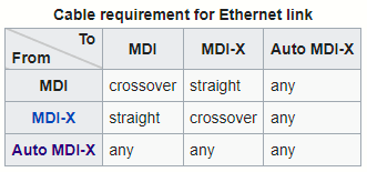
So... what happens in the end with 1000BASE-T and faster?
1000BASE-T requires Auto Negotiation to work - the fast link pulses are to be transmitted and received on specific pairs, compatible with 10BASE-T and 100BASE-TX. In theory, this requires the normal T586A/T568B crossover cable between two MDI ports or two MDI-X ports. Furthermore, the other two pairs would need to be crossed as well in order to match the expected transmitter-receiver pairs, requiring a special gigabit crossover cable as detailed in IEEE 802.3 Clause 40.8.2 Crossover function.
However, practically all 1000BASE-T interfaces support the Auto MDI-X option from Clause 40.4.4, making a crossover unnecessary. In addition, the 1000BASE-T PMA sublayer identifies each pair on each side (Clause 40.1.4), so 1000BASE-T simply works with or without single or dual crossovers (independently of the Auto MDI-X feature).
In a departure from both 10BASE-T and 100BASE-TX, 1000BASE-T and faster use all four cable pairs for simultaneous transmission in both directions through the use of telephone hybrid-like signal handling. For this reason, there are no dedicated transmit and receive pairs. 1000BASE-T and faster require either a straight or one of the crossover variants only for the autonegotiation phase. The physical medium attachment (PMA) sublayer provides identification of each pair and usually continues to work even over cable where the pairs are unusually swapped or crossed. If both devices being connected support 1000BASE-T according to the standards (Clause 40.1.4), they will connect regardless of whether a straight-through or crossover cable is used.
Gigabit and faster Ethernet links over twisted pair cable use all four cable pairs for simultaneous transmission in both directions. For this reason, there are no dedicated Tx and Rx pairs, and consequently, crossover cables are never required for 1000BASE-T communication.
Sources:
IEEE 802.3 standard
https://www.onetel.de/wp-content/uploads/2016/11/802.3-2015_SECTION3.pdf
Ethernet over twisted pair
https://en.wikipedia.org/wiki/Ethernet_over_twisted_pair
ANSI/TIA-568
https://en.wikipedia.org/wiki/ANSI/TIA-568#T568A_and_T568B_termination
Medium-dependent interfaceWhy do we need a crossover cable for 1000BASE-T?
https://en.wikipedia.org/wiki/Medium-dependent_interface
Modular connector
https://en.wikipedia.org/wiki/Modular_connector#8P8C
Ethernet crossover cable
https://en.wikipedia.org/wiki/Ethernet_crossover_cable
Why do we need a crossover cable for 1000BASE-T?
https://networkengineering.stackexchange.com/questions/46375/why-do-we-need-a-crossover-cable-for-1000base-t
CCNA 200-301 Official Cert Guide by Wendell Odom (chapter 2)
Why do we not need a crossover cable if one computer has a Gigabit ethernet card?
https://superuser.com/questions/523093/why-do-we-not-need-a-crossover-cable-if-one-computer-has-a-gigabit-ethernet-card