
Deploy the 2500 Series Wireless Controller
Introduction
The Cisco 2500 Series Wireless Controller supports a maximum of 50 lightweight APs in increments of 5 AP licenses with a minimum of a 5 AP license.
WLC 2504 ports and LAG
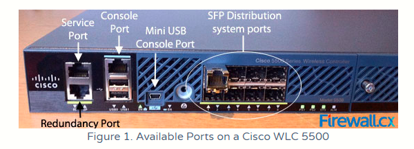
A port is a physical entity that is used for connections on the controller. Controllers have various types of ports as seen in the following image, which for comparison shows available ports on the 5500 Series:
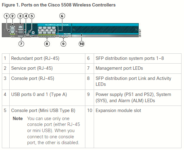
The 2500 Series have a reduced set of available ports compared to the 5500 Series:
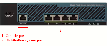
Distribution system ports
Since Console port is self-explanatory, we will discuss only DS ports, the only type of port available on the 2500 Series.
A distribution system port connects the controller to a neighbor switch (usually on 802.1Q trunk mode) and serves as the data path between these two devices. They are the most important ports on the WLC as they connect the internal logical interfaces and wireless client traffic to the rest of our network. Used for all normal AP and management traffic.
There are some restrictions for configuring DS ports:
- Each DS port is, by default, an 802.1Q VLAN trunk port. The VLAN trunking characteristics of the port are not configurable.
Some controllers support link aggregation (LAG), which bundles ALL of the controller’s distribution system ports into a single 802.3ad port channel (discussed below on this page).
- Controller configuration in access mode is not supported. It is recommended to configure controllers in trunk mode when you configure controller ports on a switch.
LAG
Link aggregation (LAG) is a partial implementation of the 802.3ad port aggregation standard. It bundles ALL of the controller’s distribution system ports into a single 802.3ad port channel. In the case of the 2500 Series, ALL four DS ports are bundled into a single logical port. This reduces the number of IP addresses required to configure the ports on your controller. When LAG is enabled, the system dynamically manages port redundancy and load balances access points transparently to the user.
If any of the controller ports fail, traffic is automatically migrated to one of the other ports. As long as at least one controller port is functioning, the system continues to operate, access points remain connected to the network, and wireless clients continue to send and receive data.
Considerations and restrictions
- You can use fast restart for any LAG changes.
- Controller does not send CDP advertisements on a LAG interface.
- LAG is supported across switches.
-
You can bundle all four ports on a Cisco 2504 Controller into a single link.
- The controller relies on the switch for the load balancing decisions on traffic that come from the network, with “source-destination IP” as the typically recommended option.
-
When using LAG make sure all ports of the controller have the same Layer 2 configuration on the switch side. For example, avoid filtering some VLANs in one port, and not the others.
-
LAG requires the EtherChannel to be configured for 'mode on' on both the controller and the Catalyst switch.
-
You cannot configure the controller’s ports into separate LAG groups. Only one LAG group is supported per controller.
-
When you enable LAG or make any changes to the LAG configuration, you must immediately reboot the controller.
-
When you enable LAG, all ports participate in LAG by default. You must configure LAG for all of the connected ports in the neighbor switch.
-
When you enable LAG, if any single link goes down, traffic migrates to the other links.
-
When you enable LAG, only one functional physical port is needed for the controller to pass client traffic.
-
If an AP is directly connected to one of the 2504 DS ports, and you enable LAG, the AP is disconnected since LAG enabling is still in the transition state. You must reboot the controller immediately after enabling LAG.
-
If you have configured a port-channel on the switch and you have not configured the AP for LAG, the AP moves to standalone mode.

WLC 2504 interfaces
An interface is a logical entity on the controller. An interface has multiple parameters associated with it, including an IP address, default gateway (for the IP subnet), primary physical port, secondary physical port, VLAN identifier, and DHCP server.
The following five types of interfaces are available on the controller. Four of these are static and are configured at setup time:
-
Management interface (static and configured at setup time; mandatory)
- AP-manager interface (static and configured at setup time; optional) - Not required for the 2500 Series because this function can be enabled by default on the management interface itself.
-
Virtual interface (static and configured at setup time; mandatory)
-
Service-port interface (static and configured at setup time; optional) - Not available for the 2500 Series.
-
Dynamic interface (user-defined)
AP-manager interface
A controller configured with IPv4 has one or more AP-manager interfaces, which are used for all L3 communications between the controller and LAPs after the APs have joined the controller. The AP-manager IP address is used as the tunnel source for CAPWAP packets from the controller to the access point and as the destination for CAPWAP packets from the access point to the controller.
- By default, the management interface acts like an AP-manager interface.
- For IPv4—The MAC address of the management interface and the AP-manager interface is the same as the base LAG MAC address.
-
An AP-manager interface is not required to be configured. The management interface acts like an AP-manager interface by default, and the access points can join on this interface.
-
If link LAG is enabled, there can be only one AP-manager interface. But when LAG is disabled, one or more AP-manager interfaces can be created, generally one per physical port.
-
When LAG is enabled—Supports only one AP Manager, which can either be on the management or dynamic interface with AP management.
-
When LAG is disabled—Supports one AP Manager per port. The Dynamic Interface tied to a VLAN can act as an AP Manager (when enabled).
When you enable LAG, all the ports would lose their AP Manager status and the AP management reverts back onto the Management interface.
-
-
Port redundancy for the AP-manager interface is not supported. You cannot map the AP-manager interface to a backup port.
-
It is not possible to have APs and a non-AP-manager interface on the same VLAN. If they are in the same VLAN, the controller will move the traffic up on the incorrect VLAN as the controller gets the CAPWAP discovery on the non-AP-manager interface.
Management interface
The management interface is the default interface for in-band management of the controller and connectivity to enterprise services, such as AAA servers. The management interface is also used for communications between the controller and APs. The management interface is the only consistently pingable in-band interface IP address on the controller. The management interface acts like an AP manager interface by default.
Ports and interfaces
The Cisco 2500 Series Wireless Controller has 4 Gigabit Ethernet ports. Each port is, by default, an 802.1Q VLAN trunk port. The VLAN trunk characteristics of the port are not configurable.
An interface is a logical entity on the controller. An interface has multiple parameters associated with it; which include the IP address, default-gateway (for the IP subnet), primary physical port, secondary physical port, VLAN tag, and DHCP server. Since LAG is not used at first, each interface is mapped to at least one primary physical port and an optional secondary port. Multiple interfaces can be mapped to a single Wireless Controller port.
There are multiple types of interfaces on the Wireless Controller, four of which are static types that must be present and are configured at setup time:
-
Management interface (static and configured at setup time; mandatory)
-
AP-manager interface - Not required for the Cisco 2500 Series Wireless Controller
-
Virtual interface (static and configured at setup time; mandatory)
-
Dynamic interface (user-defined)
Management interface
The default interface for in-band management of the controller and connectivity to enterprise services, such AAA servers. The management interface is also used for communications between the controller and APs. The management interface is the only consistently pingable in-band interface IP address on the controller. The management interface acts like an AP manager interface by default.
AP-manager interface
The dynamic interface with the Dynamic AP Management option enabled on it is used as the tunnel source for packets from the controller to the AP, and as the destination for CAPWAP packets from the AP to the cotroller. The dynamic interfaces for AP manager must have a unique IP address. Typically, this is configured on the same subnet as the management interface, but this is not necessarily a requirement. In the case of the Cisco 2500 Series Wireless Controller, a single dynamic AP manager can support any number of APs. However, as a best practice, it is suggested to have 4 separate dynamic AP manager interfaces and associate them to the 4 Gigabit interfaces. By default, the management interface acts like an AP manager interface, as well and it is associated to one Gigabit interface. As a result, if you use the management interface, you need to create only 3 more dynamic AP manager interfaces and associate them to the 3 Gigabit interfaces that remains.
If you use AP manager interfaces, the CAPWAP DISCOVERY packet that is sent initially by the APs to discover the WLC is still sent toward the management interface IP address. The management interface replies with a CAPWAP DISCOVERY RESPONSE to give the list of AP manager interfaces of the WLC. This means that the APs always need UDP 5246 and 5247 reachability to the controller management interface and that the DHCP option 43 must mention only the management interface IP address, not the AP manager IP addresses.
Virtual interface
The virtual interface is used to support mobility management, DHCP relay, and embedded Layer 3 security, such as guest web authentication and VPN termination. The virtual interface must be configured with an unassigned and unused gateway IP address. A typical virtual interface is 192.0.2.1. The virtual interface address is not pingable and must not exist in any routing table in your network.
Dynamic interface
Used to connect a VLAN to a WLAN.Dynamic interfaces are created by users and are designed to be analogous to VLANs for wireless LAN client device. The Cisco 2500 Series Wireless Controller supports up to 16 dynamic interfaces. Dynamic interfaces must be configured on a unique IP network and VLAN. Each dynamic interface acts as a DHCP relay for wireless clients associated to wireless LANs (WLANs) mapped to the interface. A WLAN associates a Service Set Identifier (SSID) to an interface and is configured with security, QoS, radio policies, and other wireless network parameters. There can be up to 16 WLANs configured per controller. Management servers, such as a RADIUS server and NTP server, must not be in a dynamic interface subnet, but must be either in the management interface subnet or any other subnet not added to the WLC.
Notes about neighboring switch configuration
By default, all four ports on the Cisco 2500 Series Wireless Controller are 802.1Q trunk ports. The controller is always connected to a Gigabit Ethernet port on the neighboring switch. The neighbor switch port is configured as an 802.1Q trunk and only the appropriate VLANs are allowed on the trunk. All other VLANs are pruned. This is not necessary, but is a deployment best practice because when irrelevant VLANs are pruned, the controller only processes relevant frames which optimizes performance.