
Lab - Path Control Using PBR
Topology
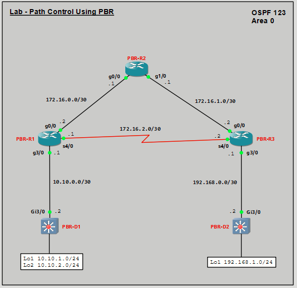
Addressing Table
|
Device |
Interface |
IPv4 Address |
Subnet Mask |
|---|---|---|---|
|
PBR-D1 |
G3/0 |
10.10.0.2 |
255.255.255.252 |
|
Loopback 1 |
10.10.1.1 |
255.255.255.0 |
|
|
Loopback 2 |
10.10.2.1 |
255.255.255.0 |
|
|
PBR-R1 |
G0/0 |
172.16.0.2 |
255.255.255.252 |
|
G3/0 |
10.10.0.1 |
255.255.255.252 |
|
|
S4/0 |
172.16.2.1 |
255.255.255.252 |
|
|
PBR-R2 |
G0/0 |
172.16.0.1 |
255.255.255.252 |
|
G1/0 |
172.16.1.1 |
255.255.255.252 |
|
|
PBR-R3 |
G0/0 |
172.16.1.2 |
255.255.255.252 |
|
G3/0 |
192.168.0.1 |
255.255.255.252 |
|
|
S4/0 |
172.16.2.2 |
255.255.255.252 |
|
|
PBR-D2 |
G3/0 |
192.168.0.2 |
255.255.255.252 |
|
Loopback 1 |
192.168.1.1 |
255.255.255.0 |
Objectives
In this lab, you will learn how to use policy-based routing to influence path section.
- Part 1: Build the Network and Configure Basic Device Settings
- Part 2: Configure and Verify Routing
- Part 3: Configure and Verify Routing
- Part 4: Configure Local PBR to Provide Path Control
Background / Scenario
In this scenario, you want to experiment with policy-based routing (PBR) to see how it is implemented and study how it could be used to influence path selection.
Your task is to connect and configure a 3 router and 2 Layer 3 switch OSPF routing domain and verify normal path selection. You will alter the traffic flow for D1 going to D2 using PBR. You will also use Cisco IOS IP SLA with PBR to achieve dynamic path control. Finally, you will configure PBR for traffic originating locally on router R1.
Note: This lab is an exercise in configuring distribute lists and redistribution using ALCs, prefix lists, and route maps.
Required Resources - Sergio Jiménez's Version
For this lab I am using GNS3, where I have deployed:
- 3 Routers (Cisco IOSv)
- 2 Switches (Cisco IOSvL2)
Instructions
Part 1: Configure Basic Device Settings and Verify Connectivity and DMVPN
PBR-R1
conf t
hostname PBR-R1
no ip domain lookup
line con 0
 logging sync
 exec-time 0 0
exit
banner motd # This is PBR-R1, Path Control Using PBR #
interface G0/0
 description Connection to PBR-R2
 ip add 172.16.0.2 255.255.255.252
 no shut
exit
interface S4/0
 description Serial Connection to PBR-R3
 ip add 172.16.2.1 255.255.255.252
 no shut
exit
interface G3/0
 description Connection to PBR-D1
 ip add 10.10.0.1 255.255.255.252
 no shut
exit
end
wr mem
!
PBR-R2
conf t
hostname PBR-R2
no ip domain lookup
line con 0
 logging sync
 exec-time 0 0
exit
banner motd # This is PBR-R2, Path Control Using PBR #
interface G0/0
 description Connection to PBR-R1
 ip add 172.16.0.1 255.255.255.252
 no shut
exit
interface G1/0
 description Connection to PBR-R3
 ip address 172.16.1.1 255.255.255.252
 no shut
exit
end
wr mem
!
PBR-R3
conf t
hostname PBR-R3
no ip domain lookup
line con 0
 logging sync
 exec-time 0 0
exit
banner motd # This is PBR-R3, Path Control Using PBR #
interface G0/0
 description Connection to PBR-R2
 ip add 172.16.1.2 255.255.255.252
 no shut
exit
interface S4/0
 description Serial Connection to PBR-R1
 ip add 172.16.2.2 255.255.255.252
 no shut
exit
interface G3/0
 description Connection to PBR-D2
 ip add 192.168.0.1 255.255.255.252
 no shut
exit
end
wr mem
!
PBR-D1
conf t
hostname PBR-D1
no ip domain lookup
line con 0
 exec-timeout 0 0
 logging synchronous
exit
banner motd # This is PBR-D1, Path Control Using PBR #
interface G3/0
 no switchport
 description Connects to PBR-R1
 ip address 10.10.0.2 255.255.255.252
 no shut
exit
interface Loopback 1
 description Interface simulates network
 ip ospf network point-to-point
 ip address 10.10.1.1 255.255.255.0
exit
interface Loopback 2
 description Interface simulates network
 ip ospf network point-to-point
 ip address 10.10.2.1 255.255.255.0
exit
end
wr mem
!
PBR-D2
conf t
hostname PBR-D2
no ip domain lookup
line con 0
 logging sync
 exec-time 0 0
exit
banner motd # This is PBR-D2, Path Control Using PBR #
interface G3/0
 no switchport
 description Connects to PBR-R3
 ip address 192.168.0.2 255.255.255.252
 no shut
exit
interface Loopback 1
 description Interface simulates network
 ip ospf network point-to-point
 ip address 192.168.1.1 255.255.255.0
exit
end
wr mem
!
Part 2: Configure and Verify Routing
In Part 2, you will implement OSPF routing for the routing domain and verify end to end routing.
Step 1: Configure Routing.
In this step, you will configure OSPF.
- On D1, advertise the connected networks using OSPF process ID 123. Also assign D1 the router ID of 1.1.1.2 and set the reference bandwidth to recognize Gigabit Ethernet interfaces.
- On R1, advertise the connected networks using OSPF process ID 123. Also assign R1 the router ID of 1.1.1.1 and set the reference bandwidth to recognize Gigabit Ethernet interfaces.
- On R2, advertise the connected networks using OSPF process ID 123. Also assign R2 the router ID of 2.2.2.1 and set the reference bandwidth to recognize Gigabit Ethernet interfaces.
- On R3, advertise the connected networks using OSPF process ID 123. Also assign R3 the router ID of 3.3.3.1 and set the reference bandwidth to recognize Gigabit Ethernet interfaces.
- On D2, advertise the connected networks using OSPF process ID 123. Also assign D2 the router ID of 3.3.3.2 and set the reference bandwidth to recognize Gigabit Ethernet interfaces.
Step 2: Verify OSPF routing
- Before configuring PBR, verify the current routing table on all devices. All routing tables look accurate.
Step 3: Verify end-to-end connectivity and path taken
- From any device, verify connectivity to all configured destinations using the following TCL script. All pings should be successful. Troubleshoot if necessary.
tclsh foreach address { 10.10.0.1 10.10.0.2 10.10.1.1 10.10.2.1 172.16.0.1 172.16.0.2 172.16.1.1 172.16.1.2 172.16.2.1 172.16.2.2 192.168.0.1 192.168.0.2 192.168.1.1 } { ping $address } - Enter tclquit to exit tcl mode.
- On D1, ping the D2 Loopback interface 192.168.1.1 address from the Lo1 interface as shown. The pings should be successful.
- Next, identify the path taken to D2 Lo1 interface using the traceroute command as shown. Notice that the path taken for the packets sourced from the D1 Lo1 LAN is going through R1 --> R2 --> R3 --> D2.
Why is the path not taking the shorter R1 --> R3 --> D2 path? - Now ping and traceroute the D2 Lo1 interface from the D1 Loopback 2 interface as shown. It is also taking the same path.
- Display the OSPF routes in the routing table of R1. R1 forwards all packets destined to the 192.168.1.0/24 network out of its G0/0 interface to R2.
- Display how R1 learned about the 192.168.1.0 network. R1 learned of the network from R2 (i.e., 172.16.0.1) who originally learned it from D2 (i.e., 3.3.3.2).
Part 3: Configure PBR to Provide Path Control
Recall that route maps can be used for:
- Redistribution - Route maps provide more options and flexibility to the redistribute command.
- Policy-based routing (PBR) - PBR allows an administrator to define routing policy other than basic destination-based routing using the routing table. The route map is applied to an interface using the ip policy route-map interface configuration command.
- BGP - Route maps are the primary tools for implementing BGP policy and allow an administrator to do path control and provide sophisticated manipulation of BGP path attributes. The route map is applied using the BGP neighbor router configuration command.
In this part, you will use PBR to configure source-based IP routing. Specifically, you will override the default IP routing decision based on the OSPF-acquired routing information for selected IP source-to-destination flows and apply a different next-hop router.
Recall that routers normally forward packets to destination addresses based on information in their routing table. By using PBR, you can implement policies that selectively cause packets to take different paths based on source address, protocol type, or application type. Therefore, PBR overrides the router’s normal routing behavior.
Configuring PBR involves configuring a route map with match and set commands and then applying the route map to the interface.
The steps required to implement path control include the following:
- Choose the path control tool to use. Path control tools manipulate or bypass the IP routing table. For PBR, route-map commands are used.
- Implement the traffic-matching configuration, specifying which traffic will be manipulated. The match commands are used within route maps.
- Define the action for the matched traffic using set commands within route maps.
- Apply the route map to incoming traffic.
Step 1: Configure PBR on R1.
As a test, you will configure the following policy on router R1:
- All traffic sourced from D1 Lo1 LAN must take the R1 --> R2 --> R3 --> D2 path.
- All traffic sourced from D1 Lo2 LAN must take the R1 --> R3 --> D2 path.
- On R1, create a standard named ACL called Lo2-ACL to identify the D1 Loopback 2 (i.e., 10.10.2.0/24) LAN.
- Create a route map called R1-to-R3 that matches Lo2-ACL and sets the next-hop interface to the R3 S4/0 interface.
- Apply the R1-to-R3 route map to the G0/0/1 interface using the ip policy route-map command.
- On R1, display the policy and matches using the show route-map command.
Note: There are currently no matches because no packets matching the ACL have passed through R1 G3/0
. - On R1, verify that the R1-to-R3 route map has been applied to the G3/0 interface.
Step 2: Test the policy.
Now you are ready to test the policy configured on R1.
- From D1, test the policy with the traceroute command, using D1 Lo1 interface as the source network.
Notice the path taken for the packet sourced from D1 Lo 1 LAN A is still going through R1 --> R2 --> R3 --> D2.
Why is the traceroute traffic not using the R3 --> R1 path as specified in the R1-to-R3 policy? - Now test the policy with the traceroute command, using D1 Lo2 interface as the source network. Now the path taken for the packet sourced from D1 Lo 2 LAN is R1 --> R3 --> D2, as expected.
- On R1, display the policy and matches using the show route-map command.
Note: There are now matches to the policy because packets matching the ACL have passed through R1 G3/0 interface. The number of packet and bytes may differ in your implementation.
Part 4: Configure Local PBR to Provide Path Control
How would you policy route packets generated by a router? The answer is to configure Local PBR.
Local PBR is a feature to policy route locally generated traffic. Local PBR policies are applied to the router with the ip local policy route-map global config command.
In this part, you will configure R1 to policy route all router generated traffic over the R1 to R3 link.
Step 1: Configure Local PBR on R1.
- Verify the path that R1 currently takes without local PBR configured. R1 sends traffic to R2 then R3 and finally D2 as expected.
- On R1, create a named extended ACL called R1-TRAFFIC which matches all IP generated packets from R1 and destined to the D2 192.162.1.0/24 network.
- On R1, create a route map called LOCAL-PBR that permits traffic matching the R1-TRAFFIC ACL and redirects it to the R3 172.16.2.2 interface.
- Create a local PBR policy that matches the LOCAL-PBR route map.
Step 2: Test Local PBR on R1.
- Verify the path taken by R1 to reach the 192.168.1.0/24 LAN. The traffic generated by R1 and going to 192.168.1.0/24 is now policy routed directly to R3 (i.e., 172.16.2.2).
- Verify the path taken by R1 to reach other networks. The traffic takes the normal OSPF generated path and is not policy routed.
- Verify the route-map counters. The local PBR policy has matched packets.
Note: The number of packets and bytes may differ in your implementation.