
Lab - Implement an IPv6 DMVPN Phase 3 Spoke-to-Spoke Topology
Topology
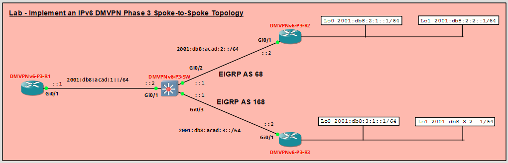
Addressing Table
|
Device |
Interface |
IPv6 Address |
Link Local |
|---|---|---|---|
|
DMVPNv6-P3-R1 |
Gi0/1 |
2001:db8:acad:1::1/64 |
fe80::1 |
|
Tunnel 1 |
2001:db8:cafe:100::1/64 |
fe80::2001 |
|
|
DMVPNv6-P3-R2 |
Gi0/1 |
2001:db8:acad:2::2/64 |
fe80::2 |
|
Loopback 0 |
2001:db8:2:1::1/64 |
fe80::2 |
|
|
Loopback 1 |
2001:db8:2:2::1/64 |
fe80::2 |
|
|
Tunnel 1 |
2001:db8:cafe:100::2/64 |
fe80::2002 |
|
|
DMVPNv6-P3-R3 |
Gi0/1 |
2001:db8:acad:3::2/64 |
fe80::3 |
|
Loopback 0 |
2001:db8:3:1::1/64 |
fe80::3 |
|
|
Loopback 1 |
2001:db8:3:2::1/64 |
fe80::3 |
|
|
Tunnel 1 |
2001:db8:cafe:100::3/64 |
fe80::2003 |
|
|
DMVPNv6-P3-SW |
Gi0/1 |
2001:db8:acad:1::2/64 |
fe80::4 |
|
Gi0/2 |
2001:db8:acad:2::1/64 |
fe80::4 |
|
|
Gi0/3 |
2001:db8:acad:3::1/64 |
fe80::4 |
Objectives
In this lab, you will create a Dynamic Multipoint Virtual Private Network (DMVPN) that consists of a hub router with two spoke routers. You will implement a DMVPN Phase 3 spoke-to-spoke topology using IPv6.
- Part 1: Build the Network and Configure Basic Device Settings
- Part 2: Implement IPv6 DMVPN Phase 3
- Part 3: Configure EIGRP for IPv6
Background / Scenario
In this lab you will configure IPv6 DMVPN Phase 3, which is very similar to the configuration with IPv4. Most of the tunnel and NHRP commands have direct parallels in IPv6. In addition, the configuration process and the differences between hub and spoke configuration is also similar. You will dynamically route overlay and transport networks over EIGRP for IPv6.
IPv6 DMVPN can be implemented in three different address type scenarios:
- IPv4 over IPv6 - IPv4 is the protocol that is used on the tunnel and IPv6 is used in the physical transport
network. - IPv6 over IPv4 - IPv6 is the tunnel protocol and IPv4 is the protocol that is used in the physical transport
network. - IPv6 over IPv6 - Both the transport and tunnel networks use IPv6.
In this lab, you will configure the IPv6 over IPv6 scenario.
Note: This lab does not include the configuration of IPsec to secure the tunnels. This essential procedure will be covered in a later lab.
Note: This lab is an exercise in configuring and verifying various implementations of DMVPN topologies and does not reflect networking best practices.
Required Resources - Sergio Jiménez's Version
For this lab I am using GNS3, where I have deployed:
- 3 Routers (Cisco IOSv)
- 1 Switch (Cisco IOSvL2)
Instructions
Part 1: Configure Basic Device Settings and Verify Connectivity
Console into each device, enter global configuration mode, and apply the basic settings. The startup configurations for each device are provided below.
DMVPNv6-P3-R1 (Hub Router)
conf t
hostname DMVPNv6-P3-R1
ipv6 unicast-routing
no ip domain lookup
banner motd # R1, Implement a DMVPN hub #
line con 0
 exec-timeout 0 0
 logging synchronous
 exit
line vty 0 4
 privilege level 15
 password cisco123
 exec-timeout 0 0
 logging synchronous
 login
 exit
ipv6 route ::/0 2001:db8:acad:1::2
interface g0/1
 ipv6 address 2001:db8:acad:1::1/64
 ipv6 address fe80::1 link-local
 no shutdown
end
wr mem
!
DMVPNv6-P3-R2 (Spoke 1)
conf t
hostname DMVPNv6-P3-R2
ipv6 unicast-routing
no ip domain lookup
banner motd # R2, Implement DMVPN Spoke 1 #
line con 0
 exec-timeout 0 0
 logging synchronous
 exit
line vty 0 4
 privilege level 15
 password cisco123
 exec-timeout 0 0
 logging synchronous
 login
 exit
ipv6 route ::/0 2001:db8:acad:2::1
interface g0/1
 ipv6 address 2001:db8:acad:2::2/64
 ipv6 address fe80::2 link-local
 no shutdown
 exit
interface loopback 0
 ipv6 address 2001:db8:2:1::1/64
 ipv6 address fe80::2 link-local
 no shutdown
 exit
interface loopback 1
 ipv6 address 2001:db8:2:2::1/64
 ipv6 address fe80::2 link-local
 no shutdown
 exit
end
wr mem
!
DMVPNv6-P3-R3 (Spoke 2)
conf t
hostname DMVPNv6-P3-R3
ipv6 unicast-routing
no ip domain lookup
banner motd # R3, Implement DMVPN Spoke 2 #
line con 0
 exec-timeout 0 0
 logging synchronous
 exit
line vty 0 4
 privilege level 15
 password cisco123
 exec-timeout 0 0
 logging synchronous
 login
 exit
ipv6 route ::/0 2001:db8:acad:3::1
interface g0/1
 ipv6 address 2001:db8:acad:3::2/64
 ipv6 address fe80::3 link-local
 no shutdown
 exit
interface loopback 0
 ipv6 address 2001:db8:3:1::1/64
 ipv6 address fe80::3 link-local
 exit
interface loopback 1
 ipv6 address 2001:db8:3:2::1/64
 ipv6 address fe80::3 link-local
 exit
end
wr mem
!
DMVPNv6-P3-SW (Layer 3 Switch)
conf t
hostname DMVPNv6-P3-SW
ipv6 unicast-routing
ip routing
no ip domain lookup
banner motd # DMVPN, DMVPN cloud switch #
line con 0
 exec-timeout 0 0
 logging synchronous
 exit
line vty 0 4
 privilege level 15
 password cisco123
 exec-timeout 0 0
 logging synchronous
 login
interface g0/1
 no switchport
 ipv6 address 2001:db8:acad:1::2/64
 ipv6 address fe80::4 link-local
 no shutdown
 exit
interface g0/2
 no switchport
 ipv6 address 2001:db8:acad:2::1/64
 ipv6 address fe80::4 link-local
 no shutdown
 exit
interface g0/3
 no switchport
 ipv6 address 2001:db8:acad:3::1/64
 ipv6 address fe80::4 link-local
 no shutdown
 exit
ipv6 route 2001:db8:2:1::/64 2001:db8:acad:2::2
ipv6 route 2001:db8:2:2::/64 2001:db8:acad:2::2
ipv6 route 2001:db8:3:1::/64 2001:db8:acad:3::2
ipv6 route 2001:db8:3:2::/64 2001:db8:acad:3::2
end
wr mem
!
Part 2: Implement IPv6 DMVPN Phase 3
In this part of the lab, you will configure IPv6 DMVPN Phase 3 to create DMVPN tunnels between the spoke routers R2 and R3, and the hub router, R1. DMVPN is very flexible and there are many options for implementation beyond what is being done in this lab.
In Phase 3 DMVPN, dynamic IPv6 spoke-to-spoke tunnels will be created between spoke routers after the initiating spoke router sends initial traffic to the hub.
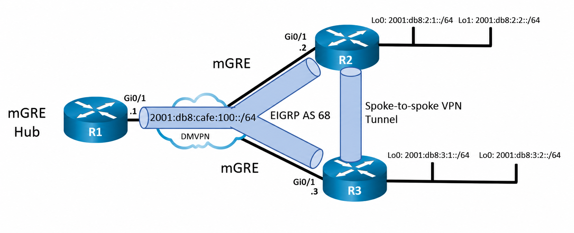
Step 1: Verify connectivity in the underlay network.
From R1, ping the Loopback 0 interfaces of R2 and R3.
Step 2: Configure the tunnel interface on the hub router.
As you know, DMVPN requires configuration of tunnel interfaces like GRE. Unlike GRE tunnels, DMVPN Phase 3 uses multipoint GRE (mGRE) mode tunnels. When configuring tunnel interfaces, care must be taken to use unique IPv6 link local addresses on all tunnel interfaces. The tunnel interfaces do not require a tunnel destination because the tunnel interfaces are multipoint.
- On R1, create the tunnel interface, set the tunnel mode to mGRE, and establish the tunnel source as Loopback 0. A tunnel key is also required when multiple tunnels will be established from a single interface. Finally, address the interface. The overlay network will use the same IPv6 network for all tunnel interfaces of the DMVPN.
- Configure the hub router as a NHRP server (NHS). Spoke routers require the services of the NHS to establish dynamic tunnels.
NHRP enables DMVPN to dynamically learn the NBMA physical addresses of devices in the network. The NHRP network ID must be consistent between the hub and spokes in the DMVPN network. You configure authentication to add a layer of security. Finally, configure the interface as multicast dynamic, which enables the NHS to dynamically add spoke routers to the NHRP table when spokes initiate a tunnel. This enables the use of dynamic routing protocols between the hub and spoke routers.
The ipv6 nhrp redirect command is required to enable the hub router to support DMVPN Phase 3. - Because DMVPN networks add information to packet headers, the interface should be fine-tuned to participate in the DMVPN network. In addition, configure the interface bandwidth so that routing protocols that use bandwidth values will function properly.
- Verify the tunnel interface configuration with the show interface tunnel 1 and show ipv6 interface tunnel 1 commands.
Step 3: Configure the R2 and R3 spoke router tunnel interfaces.
In DMVPN Phase 3, the NHRP client (NHC) tunnel interfaces use mGRE as does the NHS hub router. Much of the interface configuration is the same as for the NHS tunnel interface. However, instead of the interfaces being configured to send NHRP redirect messages, the interfaces are configured to create shortcuts, or spoke-to-spoke tunnels.
- On R2, create the tunnel interface and configure the mGRE tunnel parameters. Configuring the tunnel source as the Loopback 0 interface provides a stable source for the tunnel. The tunnel key must match the key that is configured on the hub router. Configure the overlay network IPv6 addresses for the tunnel interface. Note that no static tunnel destination is configured, because these are multipoint interfaces.
- Configure the tunnel interface as an NHRP client. You will need to designate the underlay address of the NHRP server and map the NHRP server underlay address to its overlay address.
- Adjust settings on the interface to accommodate the GRE packet overhead.
- Repeat this configuration on router R3 using the commands above and information from the addressing table.
- Verify your configurations with the show interface command. If your configurations are correct, you should be able to successfully ping the interface addresses of the overlay network from each router. R1 is show below.
- Go to R1 and view the status of DMVPN with the show dmvpn and show dmvpn detail commands. Become familiar with the output of each.
The output shows the status of the tunnel, the tunnel address, and the tunnel source address. The list of peers shows the NBMA (underlay) addresses of the DMVPN peers that were learned by NHRP. These addresses come from the tunnel source Loopback 0 addresses. Although there are only two peers known (R2 and R3), there are two entries for each. The first entry shows the tunnel target network interface address, and the second gives the link local address. The status of the entries in the table must be UP for data to travel on the tunnels. The attribute D indicates the tunnels are dynamic. If configured, the crypto settings for the tunnel would be shown. You will secure the tunnels in a later lab.
Repeat this command on the spoke routers so that you become familiar with the command output. - Verify the status of NHRP by viewing the contents of the NHRP cache with the show ipv6 nhrp detail command. Output is shown for the hub router. Note that it displays information for both of the dynamic tunnels between the spoke routers and the hub.
This output provides details about the tunnel endpoints that are known to NHRP. This incudes the overlay and transport interface addresses for the known peers.
Part 3: Configure EIGRP for IPv6
In this scenario, you will create two EIGRP for IPv6 routing processes for two different ASs. AS 68 will route the tunnel network and the LANs to be accessed across the tunnels. AS 168 will route the transport network in order to ensure connectivity between the underlay networks that the tunnel network relies upon.
Initially, static routes were configured in the topology to enable initial testing of network connectivity after the topology was set up for the lab. You no longer need these static routes and will replace them with EIGRPv6.
Step 1: Remove static routes.
- Remove the preconfigured static routes from the three routers by pasting the commands below into the console of the appropriate devices.
R1
R2
R3
SW
Note: Normally devices in the DMVPN cloud would require no intervention from enterprise networking staff. However, for the purposes of this lab, some configuration of the DMVPN Layer 3 switch is required. - Create classic mode IPv6 EIGRP processes with AS 68. This process and AS will route the overlay network. Add the tunnel interface and Loopback 1 interface networks to the routing process. Loopback 1 simulates a LAN that will be sending traffic through the tunnel. Note that split horizon is disabled on the hub and spoke router tunnel interfaces. Also note that the two spoke routers are configured as stub routers. Configure the three routers as follows:
Step 2: Configure dynamic routing for the underlay network.
- Create new classic mode EIGRP processes for AS 168. This process and AS will route the underlay, or transport, network. Note that the DMVPN Layer 3 switch did not need to have routing knowledge for the tunnel network. However, it does need to be configured to route between the point-to-point underlay networks. Split horizon does not need to be disabled for this AS because the underlay network is a point-to-point network.
Note: Normally devices in the DMVPN cloud would require no intervention from enterprise networking staff. However, for the purposes of this lab, some configuration of the DMVPN Layer 3 switch is required. - Verify dynamic routing on all three routers by using the show ipv6 route eigrp command. Do this on all three routers to verify that the underlay and overlay networks appear in the routing tables. Output is shown for the hub router.
Step 3: Verify DMVPN Phase 3 operation.
You have completed configuration of DMVPN Phase 3. Verify communication as follows:
- On R1, execute a traceroute to the Loopback 1 interface IP addresses on R2 and R3. You should see the path use the tunnel network.
- On R1, execute a traceroute to the Loopback 0 interface IP addresses on R2 and R3. You should see the path use the physical point-to-point networks of the underlay transport network.
- Repeat the traceroute commands between R2 and R3.
Step 4: Observe dynamic tunnel creation.
- Return to R2. Initiate a traceroute to the simulated LAN interface (Loopback 1) on R3. The path will pass through R1 as it does in DMVPN Phase 1.
- Issue the traceroute command again. You will now see that DMVPN hub, R1, has enabled direct spoketo-spoke communication between R2 and R3. R1 is no longer in the path, instead, the path is directly to R3. This tunnel will expire after ten minutes by default. The tunnel dynamically reopens after data is sent to the spoke router again.
- You have successfully configured a DMVPN Phase 3 network. Feel free to explore the IPv6 versions of the DMVPN Phase 3 verification commands you used for IPv4 DMVPN.