
Lab - Configure Advanced BGP Features
Topology
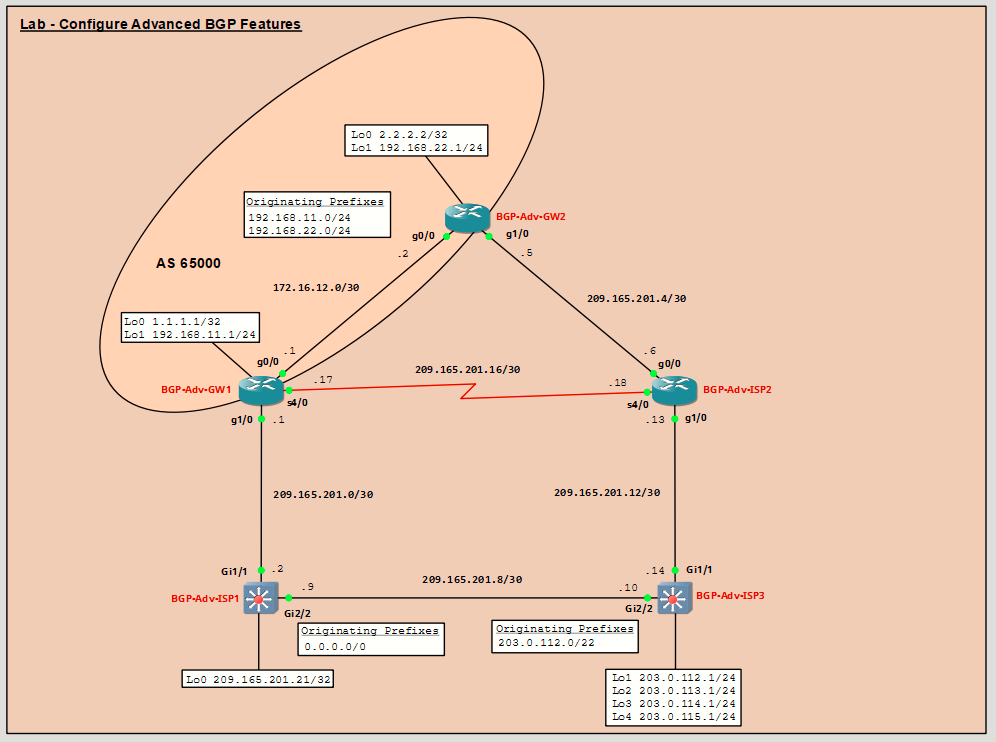
Addressing Table
|
Device |
Interface |
IPv4 Address |
IPv6 Link-Local |
|---|---|---|---|
|
BGP-Adv-GW1 |
Loopback0 |
1.1.1.1/32 |
N/A |
|
Loopback1 |
192.168.11.1/24 |
N/A |
|
|
G0/0 |
172.16.12.1/30 |
EUI-64 |
|
|
G1/0 |
209.165.201.1/30 |
N/A |
|
|
S4/0 |
209.165.201.17/30 |
N/A |
|
|
BGP-Adv-GW2 |
Loopback0 |
2.2.2.2/32 |
N/A |
|
Loopback1 |
192.168.22.1/24 |
N/A |
|
|
G0/0 |
172.16.12.2/30 |
EUI-64 |
|
|
G1/0 |
209.165.201.5/30 |
N/A |
|
|
BGP-Adv-ISP2 |
G0/0 |
209.165.201.6/30 |
N/A |
|
S4/0 |
209.165.201.18/30 |
N/A |
|
|
G1/0 |
209.165.201.13/30 |
N/A |
|
|
BGP-Adv-ISP1 |
Loopback0 |
209.165.201.21/32 |
N/A |
|
Gi1/1 |
209.165.201.2/30 |
N/A |
|
|
Gi2/2 |
209.165.201.9/30 |
N/A |
|
|
BGP-Adv-ISP3 |
Loopback1 |
203.0.112.1/24 |
N/A |
|
Loopback2 |
203.0.113.1/24 |
N/A |
|
|
Loopback3 |
203.0.114.1/24 |
N/A |
|
|
Loopback4 |
203.0.115.1/24 |
N/A |
|
|
Gi1/1 |
209.165.201.14/30 |
N/A |
|
|
Gi2/2 |
209.165.201.10/30 |
N/A |
Objectives
In this lab, you will learn how to use policy-based routing to influence path section.
- Part 1: Build the Topology and Configure Basic Device Settings and IP Addressing
- Part 2: Configure Basic eBGP and iBGP
- Part 3: Configure a Peer Group for BGP MD5 Authentication
- Part 4: Configure an AS-Path Filter
- Part 5: Configure the Local Preference Attribute and an AS-Path Filter
- Part 6: Configure the MED Attribute
- Part 7: Configure ISP1 to Advertise a Default Route in BGP
- Part 8: Configure ISP3 to Advertise a Summary (Aggregate) of its Prefixes
Background / Scenario
In this lab, OSPFv3 has already been configured on GW1 and GW2 to provide internal IPv4 reachability within AS 65000, including reachability between the loopback interfaces used for iBGP peering. You will build on this foundation by configuring traditional BGP for IPv4 on all routers, establishing iBGP and eBGP relationships and applying advanced BGP attributes and policies to control both outbound and inbound traffic behavior.
BGP may select either ISP1 or ISP2 based on default tie-breaking behavior. This can cause the installed next hop in the routing table to differ between lab runs. Where applicable this has been noted throughout the lab.
This design reflects modern dual-stack enterprise and service provider networks, where an IGP such as OSPFv3 provides internal reachability while BGP, using address families, controls inter-AS routing and policy.
Note: Although the BGP standards (e.g., RFC 4271) define the abbreviations as EBGP and IBGP, modern vendor documentation often uses the lower-case forms eBGP and iBGP to visually distinguish “external” or “internal” from the core BGP protocol name. We will use lower case e and i to make is easier to visually distinguish these two protocols.
Required Resources - Sergio Jiménez's Version
For this lab I am using GNS3, where I have deployed:
- 3 Routers (Cisco 7200)
- 2 Switches (Cisco IOSvL2)
Instructions
Part 1: Configure Basic Device Settings and Verify Connectivity and DMVPN
BGP-Adv-GW1
conf t
hostname BGP-Adv-GW1
no ip domain lookup
line con 0
 exec-timeout 0 0
 logging sync
exit
ipv6 unicast-routing
!
interface Loopback0
 ip address 1.1.1.1 255.255.255.255
 ipv6 enable
 ospfv3 1 ipv4 area 0
exit
!
interface Loopback1
 ip address 192.168.11.1 255.255.255.0
exit
!
interface GigabitEthernet0/0
 description To BGP-Adv-GW2
 ip address 172.16.12.1 255.255.255.252
 ipv6 enable
 ospfv3 1 ipv4 area 0
 no shutdown
exit
!
interface GigabitEthernet1/0
 description To BGP-Adv-ISP1
 ip address 209.165.201.1 255.255.255.252
 no shutdown
exit
!
interface Serial4/0
 description To BGP-Adv-ISP2 - slower link
 ip address 209.165.201.17 255.255.255.252
 no shutdown
exit
!
router ospfv3 1
 router-id 1.1.1.1
 address-family ipv4 unicast
  passive-interface default
  no passive-interface GigabitEthernet0/0
 exit-address-family
end
wr mem
!
BGP-Adv-GW2
conf t
hostname BGP-Adv-GW2
ipv6 unicast-routing
line con 0
 exec-timeout 0 0
 logging sync
exit
no ip domain lookup
!
interface Loopback0
 ip address 2.2.2.2 255.255.255.255
 ipv6 enable
 ospfv3 1 ipv4 area 0
exit
!
interface Loopback1
 ip address 192.168.22.1 255.255.255.0
exit
!
interface GigabitEthernet0/0
 description To BGP-Adv-GW1
 ip address 172.16.12.2 255.255.255.252
 ipv6 enable
 ospfv3 1 ipv4 area 0
 no shutdown
exit
!
interface GigabitEthernet1/0
 description To BGP-Adv-ISP2 - faster link
 ip address 209.165.201.5 255.255.255.252
 no shutdown
exit
!
router ospfv3 1
 router-id 2.2.2.2
 address-family ipv4 unicast
  passive-interface default
  no passive-interface GigabitEthernet0/0
 exit-address-family
end
wr mem
!
BGP-Adv-ISP1
conf t
hostname BGP-Adv-ISP1
no ip domain lookup
line con 0
 exec-timeout 0 0
 logging sync
exit
ip routing
!
interface Loopback0
 ip address 209.165.201.21 255.255.255.255
exit
!
interface GigabitEthernet1/1
 no switchport
 description To BGP-Adv-GW1
 ip address 209.165.201.2 255.255.255.252
 no shutdown
exit
!
interface GigabitEthernet2/2
 no switchport
 description To BGP-Adv-ISP3
 ip address 209.165.201.9 255.255.255.252
 no shutdown
exit
end
wr mem
!
BGP-Adv-ISP2
conf t
hostname BGP-Adv-ISP2
no ip domain lookup
line con 0
 exec-timeout 0 0
 logging sync
exit
!
interface GigabitEthernet0/0
 description To BGP-Adv-GW2
 ip address 209.165.201.6 255.255.255.252
 no shutdown
exit
!
interface Serial4/0
 description To BGP-Adv-GW1 - slower link
 ip address 209.165.201.18 255.255.255.252
 no shutdown
exit
!
interface GigabitEthernet1/0
 description To BGP-Adv-ISP3
 ip address 209.165.201.13 255.255.255.252
 no shutdown
exit
end
wr mem
!
BGP-Adv-ISP3
conf t
hostname BGP-Adv-ISP3
no ip domain lookup
line con 0
 exec-timeout 0 0
 logging sync
exit
ip routing
!
interface Loopback1
 ip address 203.0.112.1 255.255.255.0
exit
!
interface Loopback2
 ip address 203.0.113.1 255.255.255.0
exit
!
interface Loopback3
 ip address 203.0.114.1 255.255.255.0
exit
!
interface Loopback4
 ip address 203.0.115.1 255.255.255.0
exit
!
interface GigabitEthernet1/1
 no switchport
 description To BGP-Adv-ISP2
 ip address 209.165.201.14 255.255.255.252
 no shutdown
exit
!
interface GigabitEthernet2/2
 no switchport
 description To BGP-Adv-ISP1
 ip address 209.165.201.10 255.255.255.252
 no shutdown
exit
end
wr mem
!
Part 2: Configure Basic eBGP and iBGP
In this part, you will review the existing OSPFv3 configuration on the gateway routers to confirm internal IPv4 reachability and verify that loopback interfaces used for iBGP peering are correctly learned through OSPFv3. You will then configure a combination of iBGP and eBGP sessions across the topology, using loopback-based iBGP between gateway routers for resiliency and eBGP connections to multiple ISPs to simulate external connectivity.
You will advertise local prefixes into BGP, verify that routes are exchanged successfully across all autonomous systems, and confirm end-to-end reachability by examining IPv4 routing tables. Finally, you will explore how 16-bit and 32-bit AS numbers coexist in BGP, including how Cisco devices display and convert between asplain and asdot notation, reinforcing both practical configuration skills and conceptual understanding of modern BGP operation.
Step 1: Examine commands used for OSPFv3 in GW1 and GW2 running-configs.
Before configuring BGP, examine the existing OSPFv3 configuration on GW1 and GW2. OSPFv3 has already been configured to provide internal reachability between the gateway routers. This step is intended to familiarize you with how OSPFv3 is enabled and verified in the running configuration before proceeding with the BGP configuration.
Step 2: Verify the IPv4 routing tables for OSPFv3 routes.
Examine the IPv4 routing table on each router and confirm that the Loopback0 address of the other gateway has been learned via OSPFv3. The presence of an OSPF-learned /32 route confirms that OSPFv3 is correctly exchanging IPv4 routing information and that the loopback interfaces used for iBGP peering are reachable.
At this point, no default route should be present, and only the internal OSPFv3 routes should appear in the routing table.
Step 3: Configure BGP (iBGP-eBGP) on GW1.
In this step, you will configure BGP on GW1 to establish both internal BGP (iBGP) and external BGP (eBGP) neighbor relationships.
The iBGP session between GW1 and GW2 is configured using the Loopback0 interfaces with the update-source loopback0 command. Using loopback addresses for iBGP provides a more resilient and realistic design, as loopbacks remain reachable even if the physical path between routers changes. In a real-world topology, there would typically be multiple paths between gateway routers, and using loopbacks ensures the iBGP session is not tied to a single physical interface.
Because GW1 and GW2 are acting as gateway routers and exchange routes learned from external eBGP peers via iBGP, the next-hop-self command must be configured on both routers. Without next-hop-self, routes learned from an eBGP neighbor would retain their original external next-hop address when advertised via iBGP.
GW1 also establishes eBGP sessions with ISP1 and ISP2, representing connections to external autonomous systems. Finally, GW1 advertises the 192.168.11.0/24 network into BGP, making this local prefix reachable by external peers.
Step 4: Configure BGP (iBGP-eBGP) on GW2.
This step mirrors the BGP configuration performed on GW1. GW2 is configured with an iBGP session to GW1 using the Loopback0 interface for resiliency, along with an eBGP session to ISP2. GW2 then advertises its local prefix, 192.168.22.0/24, into BGP.
Step 5: Configure BGP (eBGP) on ISP2.
In this step, ISP2 is configured with external BGP (eBGP) sessions to both gateway routers in AS 65000 as well as to ISP3. These peerings allow ISP2 to participate in external route exchange and later serve as a policy decision point for traffic entering and leaving AS 65000.
Step 6: Configure BGP (eBGP) on ISP3.
In this step, ISP3 is configured as an external autonomous system using a 32-bit ASN. ISP3 establishes eBGP sessions with ISP1 and ISP2 and originates four IPv4 prefixes (203.0.112.0/24 through 203.0.115.0/24) into BGP. These routes represent external networks and will later be used to demonstrate BGP policy behavior and route aggregation.
Note: 32-bit ASNs will be explained in a later step.
Step 7: Configure eBGP on ISP1.
In this step, ISP1 is configured with external BGP (eBGP) sessions to both the customer AS (65000) and ISP3. These eBGP peerings allow ISP1 to exchange routing information between the customer network and the upstream provider. This step must be performed only after GW1 has learned the ISP3 prefixes via ISP2, ensuring that ISP2 is the initially selected and oldest path using show ip route bgp.
After GW1 has ISP3 prefixes showing 2.2.2.2 (GW2) as the next-hop router, configure BGP on ISP1.
Note on Configuration Sequence: In this lab, BGP is intentionally configured on all routers except ISP1 first to ensure deterministic behavior. Before ISP1 participates in BGP, GW1 learns the ISP3 prefixes only via ISP2, making that path the oldest and initially installed route. When ISP1 is later configured and begins advertising the same prefixes, all higher-priority BGP attributes (weight, local preference, AS path length, origin, and MED) are equal, so the BGP decision process falls to its final tie-breaking steps. Because the path via ISP2 was learned first and ISP2 has a lower configured BGP router ID than ISP1, GW1 continues to prefer ISP2 as the outbound path.
Note on Router-IDs: BGP router IDs are explicitly configured on ISP1 and ISP2 to provide another deterministic tie-breaker in the BGP best-path selection process, after oldest path The configured BGP router IDs on ISP1 and ISP2 are not the primary reason for path selection at this point. Instead, they serve as a fallback mechanism that would be used only if the paths were received at the same time and remained otherwise indistinguishable (oldest path not a factor). In that case, BGP would select the path from the peer with the lower router ID.
Important: In real-world networks, autonomous systems do not typically rely on oldest-path or a peer’s router ID to influence routing decisions. Oldest-path or router ID are used only as a last-resort tie-breaker as they provide no policy control. Production networks instead use attributes such as Local Preference (for outbound traffic control) and MED (for influencing inbound traffic) to enforce intentional routing policy. These attributes will be configured and explored later in this lab.
Step 8: Examine IPv4 routing tables and verify reachability.
In this step, examine the IPv4 BGP entries in the routing tables on each router to verify that all autonomous systems have reachability to every originated BGP prefix. The presence of these routes confirms that iBGP and eBGP sessions are established correctly and that BGP is successfully exchanging routing information across the topology. Before examining the routing tables, note which prefixes are originated by each AS.
AS 65000 (GW1 and GW2)
- GW1 originates: 192.168.11.0/24
- GW2 originates: 192.168.22.0/24
AS 65300.3 (ISP3 - 32-bit ASN) originates
- 203.0.112.0/24
- 203.0.113.0/24
- 203.0.114.0/24
- 203.0.115.0/24
AS 65100 (ISP1)
- Does not originate customer prefixes in this step
AS 65200 (ISP2)
- Does not originate customer prefixes in this step.
At this point, all BGP-originated prefixes, whether learned via eBGP or iBGP, should be present in the IPv4 routing tables of every router in the topology, confirming full end-to-end reachability.
Note: At this stage of the lab, no outbound BGP policy has been configured on GW1. As a result, multiple external paths to the same destination may appear equivalent, and BGP may select either ISP1 or ISP2 based on default tie-breaking behavior. This can cause the installed next hop in the routing table to differ between lab runs. This behavior is expected and demonstrates the need for Local Preference (later in this lab) to enforce a consistent outbound path selection policy.
Step 9: Understanding 32-bit ASNs.
- Originally, BGP AS numbers were 16-bit values, which limited the Internet to about 65,000 ASes. As the Internet grew and more organizations became multihomed, this space was exhausted. To solve this, 32- bit AS numbers were introduced, expanding the AS number space dramatically while remaining compatible with older routers.
Modern network operating systems fully support both 16-bit and 32-bit ASNs, allowing them to coexist within the same BGP AS path without affecting routing behavior.
Representing 32-bit ASNs
Although a 32-bit AS number is assigned as a single numeric value, it can be displayed in two different formats. Cisco devices support both formats, and the choice affects only how the AS number is shown, not how BGP operates.
-
- asplain format: Displays the AS number as a single 32-bit integer (for example, 4279500803).
- asdot format: Displays the same 32-bit AS number as two 16-bit values separated by a dot (for example, 65300.3).
Both formats represent the same AS number, and routing behavior is identical regardless of which format is used.
The following BGP output shows how 16-bit and 32-bit ASNs coexist in the same AS path. In this example, 65200 represents a traditional 16-bit ASN, while 4279500803 represents a 32-bit ASN in asplain format. Modern BGP implementations handle both seamlessly, and the presence of both values in the AS path does not affect route selection or reachability.
- asplain format: Displays the AS number as a single 32-bit integer (for example, 4279500803).
-
- By default, Cisco routers display 32-bit AS numbers in asplain format, which shows the AS as a single large integer. The bgp asnotation dot command changes only how 32-bit ASNs are displayed, not how BGP operates.
After enabling dot notation, the same 32-bit ASN that previously appeared as 4279500803 is now shown in asdot format as 65300.3. This format splits the 32-bit value into two 16-bit components, making the AS path easier to read and interpret.
Note: Use the no bgp asnotation dot command to return to the default asplain format. - Converting from asplain to asdot Notation.
A 32-bit AS number (asplain) is a single numeric value. To display it in asdot notation, the number is split into two 16-bit components.
To convert asplain (4279500803) to asdot:
1. Divide the 32-bit AS number by 65,536
4279500803 / 65,536 = 65,300 remainder 3
2. The quotient becomes the first value (X)
X = 65000
3. The remainder becomes the second value (Y)
Y = 3
Resulting in the asdot notation: 65000.3 - Converting from asdot to asplain Notation.
An AS number written in asdot format represents two 16-bit values joined together. To convert it back to the asplain (single 32-bit) value, the two components are recombined mathematically.
To convert asdot (65300.3) to asplain:
1) Multiply the first value (X) by 65,536
65,300 x 65,536 = 4,279,500,800
2) Add the second value (Y)
4,279,500,800 + 3 = 4,279,500,803
Resulting in the asplain notation: 4279500803 - Private 32-bit AS Number Ranges.
In addition to the traditional 16-bit private AS range, a large block of 32-bit AS numbers is also reserved for private use and is not advertised on the public Internet.
asplain format:
- 4200000000 – 4294967294
asdot format (equivalent):
- 64086.64086 – 65535.65534
These private 32-bit ASNs function exactly like public ASNs in BGP but are intended for lab environments, private networks, and internal routing designs. As with private 16-bit ASNs, they should not be used on the public Internet.
Part 3: Configure a Peer Group for BGP MD5 Authentication
In networks where a router peers with multiple BGP neighbors that share common settings (timers, authentication, inbound/outbound policy, etc.), configuring each neighbor individually can become repetitive and error-prone. A BGP peer group allows you to define these shared settings once and then apply them to multiple neighbors. Each neighbor still keeps its own unique properties (such as remote-as and neighbor IP), but inherits the common settings from the peer group.
In this lab, GW1 is multihomed to two different ISPs (ISP1 and ISP2), making it an ideal place to use a peer group. You will create a peer group on GW1 and apply it to both eBGP neighbors. In the next part, you will use BGP MD5 authentication as a real-world example of why peer groups are useful.
Step 1: Configure a peer group on GW1.
Create a peer group on GW1 for its eBGP ISP neighbors and apply the peer group to:
- ISP1 neighbor 209.165.201.2 (AS 65100)
- ISP2 neighbor 209.165.201.18 (AS 65200)
Note: A peer group can include neighbors in different ASes. The remote-as is still configured per neighbor, while common settings are applied through the peer group.
Step 2: Verify that both neighbors are present and established.
Confirm that both neighbors are still present and established. In the show ip bgp summary output, a numeric value in the State/PfxRcd column indicates that the BGP session is established and shows the number of prefixes received from that neighbor.
Step 3: Configure BGP MD5 authentication.
BGP sessions run over TCP, and by default they are not authenticated. BGP supports MD5 authentication, which adds a shared secret to the TCP session to protect against unauthorized peers and spoofed connections.
When MD5 authentication is configured on a BGP peer group, the authentication settings are applied consistently to all neighbors that belong to that peer group. This is a common real-world use case for peer groups and mirrors the configuration approach used in the Cisco reference lab.
In this step, you will configure MD5 authentication between GW1 and its external BGP neighbors ISP1 and ISP2.
On GW1, apply the MD5 password to the existing peer group. This single command enables authentication for both eBGP neighbors in the group. A BGP session may not visibly reset when MD5 authentication is added if the matching password is configured quickly on both peers; authentication is verified by the session remaining established.
Step 4: Configure matching MD5 authentication on ISP1.
ISP1 must be configured with the same password for the BGP session with GW1.
Step 5: Configure matching MD5 authentication on ISP2.
ISP2 must also be configured with the same password for its BGP session with GW1.
Step 6: Verifying peer group membership and BGP session state.
The output confirms that both eBGP neighbors on GW1 are members of the peer group ISP-PEERS, indicating that they inherit the shared peer-group settings, including MD5 authentication. The BGP state = Established for each neighbor verifies that the authenticated BGP sessions are up and stable and that GW1 is successfully exchanging routing information with both ISP neighbors.
Part 4: Configure an AS-Path Filter (Prevent AS 65000 from Becoming a Transit AS)
At this point in the lab, GW1 and GW2 are fully multihomed, with BGP connectivity to multiple service providers. While this provides redundancy, it also introduces an unintended side effect: without additional policy controls, ISP1 and ISP2 could potentially use AS 65000 as a transit path to reach other external networks if a direct path fails.
A transit AS is an autonomous system that forwards traffic between other autonomous systems even though it is neither the source nor the destination of that traffic.
In real-world deployments, customer networks do not act as transit autonomous systems for their providers. AS 65000 should advertise only its own locally originated prefixes and should never forward traffic between ISPs.
To enforce this behavior, AS 65000 will use an outbound AS-path filter. Locally originated routes are easily identified because they have an empty AS-path attribute. By permitting only routes with an empty AS path and denying all others, AS 65000 ensures that it advertises only its own prefixes and does not become a transit AS.
AS-path filters use AS-path access lists, which rely on regular expressions to match patterns in the ASpath attribute. In this lab, you will use a simple and commonly deployed expression to allow only locally sourced routes.
Commonly Used AS-Path Regular Expression Characters
|
Symbol |
Meaning |
|---|---|
|
|
Beginning of the AS path |
|
|
End of the AS path |
|
|
AS delimiter (beginning, end, or space between AS numbers) |
|
|
Any single character |
|
|
Any number of characters (match anything) |
|
|
One or more occurrences of the previous pattern |
|
|
Zero or more occurrences of the previous pattern |
|
|
Zero or one occurrence of the previous pattern |
|
|
Escapes a special character |
|
|
Matches a range or set of characters |
Note: In BGP AS-path filtering, AS numbers are treated as a string, not as numeric values.
Common AS-Path Regular Expression Examples
|
Regular Expression |
Description |
|---|---|
|
|
Matches locally originated routes only (empty AS path) |
|
|
Matches routes originating in AS 65000 |
|
|
Matches routes originating in AS 65000 |
|
|
Matches routes received from AS 65000 |
|
|
Matches routes that passed through AS 65000 |
|
|
Matches all routes |
|
|
Matches any AS number |
|
|
Matches an AS number repeated any number of times (AS-path prepending) |
|
|
Matches a specific AS path sequence |
Step 1: Verify AS 65000 is currently a transit AS.
The BGP table on ISP1 shows that AS 65000 is currently functioning as a transit AS, meaning it is advertising routes learned from one external AS to another external AS.
The BGP table on ISP1 shows possible routes where the first AS in the AS path is 65000, followed by other AS numbers. This indicates that the routes were learned from AS 65000, even though they originated in a different AS. Because AS 65000 is advertising routes that it learned from one external provider to another external provider, it is functioning as a transit AS, allowing traffic to pass through its network rather than advertising only its own locally originated prefixes.
Note: Earlier in this lab we stated that no outbound BGP policy has been configured on GW1. As a result, multiple external paths to the same destination may appear equivalent, and BGP may select either ISP1 or ISP2 based on default tie-breaking behavior. Because of this, AS 65000 may appear as a transit AS when examining the BGP table on either ISP1 or ISP2, depending on which path is currently preferred. If AS 65000 does not appear as the first AS followed by other AS numbers in the AS path on ISP1, you should examine the BGP table on ISP2 instead.
Step 2: Configure an outbound AS-Path filter on GW2 (prevent transit).
GW2 will be configured to advertise only locally originated routes to its ISP neighbor (ISP2). This prevents AS 65000 from acting as a transit AS. Applying the filter-list with out controls what GW2 advertises to ISP2, allowing only GW2’s locally originated prefixes and preventing it from advertising routes learned from other neighbors (such as via iBGP from GW1).
AS-path regular expression: ^$
The AS-path access list uses a regular expression to match the AS-path attribute:
- ^ = beginning of the AS-path string
- $ = end of the AS-path string
- ^$ therefore matches an empty AS path
An empty AS path means the route was originated locally on this router (for example, via a network statement). Routes learned from eBGP neighbors will have one or more AS numbers in the path and will not match ^$
Why apply the filter-list out
Applying the filter-list with out means the filter controls what GW2 advertises to its neighbor. In other words:
- GW2 will advertise its own prefixes.
- GW2 will not advertise routes learned from other neighbors (such as via iBGP from GW1) to ISP2.
- This prevents AS 65000 from being used as a transit path
Step 3: Configure an outbound AS-Path filter on GW1 (prevent transit).
In this step, GW1 is configured to advertise only locally originated routes to its external BGP neighbors. Because GW1 uses a peer group for its ISP neighbors, the AS-path filter can be applied once to the peer group and automatically inherited by both ISP1 and ISP2.
Step 4: Verify AS 65000 is no longer a transit AS.
After applying the outbound AS-path filters on GW1 and GW2, re-examine the BGP table on ISP1 (or ISP2 if applicable) again.
Notice AS Path column for the external prefixes (203.0.112.0/24–203.0.115.0/24). These routes now show an AS path of: 4279500803. (AS 4279500803 is shown in asplain notation because we did not use the BGP bgp asnotation dot command on ISP1.)
This indicates that the routes are learned directly from ISP3, without passing through AS 65000. The absence of 65000 in the AS path for these external routes confirms that AS 65000 is no longer advertising routes learned from one ISP to another.
In contrast, the customer prefixes (192.168.11.0/24 and 192.168.22.0/24) still include 65000 in the AS path, which is expected because these routes originate in AS 65000.
In other words, if AS 65000 does not appear in an AS path followed by other AS numbers for routes that originate in different ASes, then AS 65000 is no longer acting as a transit AS.
Note: It may take a moment for BGP to reconverge.
Part 5: Configure the Local Preference Attribute and an AS-Path Filter
This part defines outbound traffic policy from the perspective of GW1, which acts as the primary exit point for AS 65000 and shares its routing decisions with GW2 using iBGP.
AS 65000 is a multihomed customer connected to multiple service providers. Although AS 65000 has multiple external paths, it has clear outbound traffic preferences based on link capacity and design intent:
- Primary exit: GW1 → ISP1 (fastest and most preferred link)
- Secondary exit: GW1 → ISP2
- Tertiary / last-resort exit: GW1 → GW2 → ISP2 (used only when both GW1 uplinks are unavailable)
To enforce this policy, AS 65000 must influence outbound path selection, not inbound traffic. This is accomplished by manipulating the Local Preference attribute, which is evaluated inside the AS and is not advertised to external neighbors.
In addition, AS 65000 must remain a non-transit AS, meaning it should not carry traffic between its ISPs. An AS-path filter is used alongside Local Preference to ensure only appropriate routes are selected and advertised.
Why Local Preference Is the Correct Tool Here
- Local Preference controls which exit point is chosen for outbound traffic.
- Higher Local Preference = more preferred path.
- It is evaluated before AS-path length in the BGP decision process.
- It applies only within AS 65000, making it ideal for customer policy.
This aligns perfectly with our design goal: “Prefer ISP1 first, then ISP2 via GW1, and only use GW2 → ISP2 if everything else fails.”
|
Path |
Role |
Local Preference |
|---|---|---|
|
GW1 → ISP1 (AS 65100) |
Primary |
200 |
|
GW1 → ISP2 (AS 65200) |
Secondary |
150 |
|
GW1 → GW2 → ISP2 (AS 65200) |
Backup |
100 (default) |
Because GW1 and GW2 exchange routes via iBGP, Local Preference set on GW1 is propagated to GW2 automatically.
Step 1: Match routes learned from ISP1 (AS 65100).
On GW1, create an AS-path access list that matches routes received from ISP1.
Explanation:
- ^65100_ matches routes where 65100 is the first AS in the AS path.
- These routes are learned directly from ISP1.
- This allows us to identify traffic that should use the preferred exit.
Step 2: Examine the GW1 IPv4 routing table (before applying local preference)
At this stage of the lab, no Local Preference policy has been applied on GW1. As a result, BGP may select either ISP1 or ISP2 as the outbound path for external prefixes based on default BGP tie-breaking behavior.
Depending on timing and route processing order, GW1 may choose the path via ISP2, even though it is connected over a slower serial link. This behavior is expected and highlights the fact that, without explicit policy, BGP does not consider link speed or design intent when selecting paths.
The output below shows GW1 currently using ISP2 as the next hop for the external prefixes 203.0.112.0/24 through 203.0.115.0/24.
This reinforces the need for Local Preference, which will be configured next to enforce a consistent outbound policy that prefers ISP1 first, ISP2 second, and uses GW2 only as a last resort.
Step 3: Create a route map to set local preference.
Create a route map on GW1 that uses AS-path matching to set Local Preference values, influencing which ISP link is preferred for outbound traffic from AS 65000.
Explanation:
- Routes from ISP1 receive Local Preference 200
- All other external routes learned on GW1 receive Local Preference 150
- The default Local Preference (100) is preserved for routes learned via GW2
Step 4: Apply the route map inbound on GW1.
Because GW1 uses a peer group, this policy is applied once and inherited by both ISP neighbors. Applying the route map inbound (in) ensures the Local Preference is set as routes enter AS 65000.
Step 5: Refresh BGP sessions.
Perform a soft inbound reset to make the new Local Preference values take effect.
These commands perform a soft inbound reset of the BGP sessions with ISP1 and ISP2. The BGP adjacencies remain established, but the routes are re-received and reprocessed so the new Local Preference values can be applied without tearing down the sessions.
This does not clear the entire BGP table or reset the TCP session; it simply forces the neighbors to resend updates so BGP can recalculate the best paths using the updated policy.
Step 6: Verify local preference.
This output verifies that BGP is selecting best paths based on the configured Local Preference values applied inbound on GW1.
Note: It may take a moment for BGP to reconverge.
For each external prefix (203.0.112.0/24 through 203.0.115.0/24), GW1 now has two external paths:
- One learned directly from ISP1 (AS 65100).
- One learned directly from ISP2 (AS 65200).
- The Local Preference values clearly reflect the configured policy:
- Routes learned from ISP1 have a Local Preference of 200.
- Routes learned from ISP2 have a Local Preference of 150.
Because Local Preference is evaluated before AS-path length and other attributes, GW1 correctly selects the ISP1 path as the best path for all external prefixes, as indicated by the *> marker.
Routes learned via GW2 do not appear in the BGP table on GW1 because GW1 already has better local exits for those destinations. Because BGP advertises only the best path to iBGP peers by default, alternate paths learned via GW2 are neither selected nor advertised back to GW1.
This confirms that outbound traffic from AS 65000 will:
- Prefer GW1 → ISP1
- Fall back to GW1 → ISP2
- Use GW1 → GW2 → ISP2 only if both GW1 external links fail
Step 7: Re-Examine the GW1 IPv4 routing table (after applying local preference).
Examining the IPv4 routing table on GW1 verifies that the Local Preference policy is now reflected in the IPv4 routing table on GW1, with all external prefixes installed using the preferred exit via ISP1.
Step 8: Verify GW2 selected the iBGP-learned path from GW1.
Although GW2 has a directly connected eBGP path to ISP2, it selects the iBGP-learned path via GW1 because the Local Preference value (200) is higher than the default Local Preference (100) of the eBGP path. Local Preference is evaluated before the eBGP-versus-iBGP check in the BGP decision process, allowing routing policy defined on GW1 to influence exit selection across the entire AS. This confirms that Local Preference is the correct attribute for enforcing consistent outbound traffic policy within AS 65000.
Note: In the BGP route selection process, an eBGP path is preferred over iBGP path. This is evaluated after Local Preference.
The i flag indicates that a route was learned via iBGP, while the absence of i indicates a route learned directly via eBGP.
Step 9: Confirm outbound path selection on GW2.
This output confirms that the BGP best paths selected on GW2 are now installed in the IPv4 routing table, with all external prefixes forwarded via GW1 as dictated by the Local Preference policy.
Part 6: Configure the MED Attribute
In this part of the lab, you will configure the Multi-Exit Discriminator (MED) attribute to influence inbound traffic from ISP2 into AS 65000. Unlike Local Preference, which is used internally by AS 65000 to select outbound paths, MED is an attribute that an AS advertises to a neighboring AS to suggest which ingress point should be preferred.
In this topology, AS 65000 is multihomed to ISP2 through two different gateways: GW1 and GW2. The goal is for ISP2 to prefer the path toward GW2 when sending traffic into AS 65000, rather than entering through GW1. This allows AS 65000 to influence how inbound traffic from ISP2 is distributed across its gateways.
In this part of the lab, you will configure MED attribute on GW1 and GW2 in AS 65000 to influence how ISP2 selects its preferred ingress point to use when sending traffic into AS 65000. Unlike Local Preference, which controls outbound traffic inside an AS, MED is used to influence inbound traffic decisions made by a neighboring AS.
It is important to understand that MED has low priority in the BGP decision process and is considered only after attributes such as Weight and Local Preference—attributes that are controlled by the receiving AS. Because of this, MED is often overridden in real networks and should be viewed as a hint, not a guarantee. In practice, MED is most effective when used between directly connected autonomous systems where both sides agree to honor it.
This section demonstrates how MED can be used to influence inbound path selection from ISP2, while also reinforcing why Local Preference remains the primary tool for controlling outbound traffic within AS 65000.
Step 1: Examine the ISP2 BGP routing table (before MED).
Before configuring MED, examine the BGP-learned routes on ISP2. At this stage, ISP2 has no MED information to differentiate the two entry points into AS 65000, so path selection is based on default BGP tiebreaking behavior.
Before MED is configured, ISP2 has no policy-based way to distinguish between GW1 and GW2. As a result, ISP2 may choose either gateway as the preferred next hop for traffic destined to AS 65000, but it will consistently use the same gateway for all prefixes.
Or
Step 2: Configure MED on GW2 (preferred ingress).
GW2 will advertise routes to ISP2 with a lower MED, making it the preferred entry point into AS 65000.
Explanation:
- MED is set using the set metric command.
- A lower MED value (50) makes this path more attractive.
- The route map is applied outbound, because MED is sent to the neighbor.
- This configuration tells ISP2 to prefer routes entering AS 65000 via GW2.
Step 3: Configure MED on GW1 (backup ingress).
In this step, GW1 advertises routes with a higher MED value so that, when ISP2 has a choice of entering AS 65000 via GW1 or GW2, it will prefer GW2 (lower MED) and treat GW1 as the less-preferred entry point.
Important Note About Peer Groups (Why We Apply the Route Map This Way)
On GW1, ISP1 and ISP2 are members of the ISP-PEERS peer group. Because of this, IOS-XE does not allow you to apply a route map directly to an individual peer-group member using a neighbor route-map ... command. If you try, IOS-XE rejects it with:
Therefore, the route map must be applied to the peer group, which means the MED policy is applied to both ISP neighbors on GW1. In a production design, you could use a separate peer group (or more granular policy) to apply MED only toward ISP2, but that added complexity is not required for this lab.
Explanation:
- GW1 now sets MED to 100 on routes it advertises to neighbors in the ISP-PEERS peer group.
- This makes GW1 the less preferred ingress point compared to GW2 (which will be configured with a lower MED).
- Using explicit MED values on both gateways gives ISP2 a clear basis to compare the two entry points into AS 65000.
Step 4: Refresh BGP sessions with ISP2.
To ensure ISP2 receives the updated MED values, reset the BGP sessions. This clears and reestablishes the BGP sessions so the updated MED values are advertised and processed by ISP2.
Step 5: Verify MED influence on ISP2.
Re-examine the BGP routing table on ISP2. You should now observe that routes destined for AS 65000 consistently prefer the path via GW2, reflecting the lower MED value advertised by GW2.
From the output:
- For prefixes 192.168.11.0/24 and 192.168.22.0/24, ISP2 now sees multiple paths into AS 65000:
- Via GW2 (209.165.201.5) with MED 50.
- Via GW1 (209.165.201.17) with MED 100
- Because lower MED values are preferred, ISP2 selects the paths via GW2, as indicated by the *> bestpath marker.
- This demonstrates that ISP2 is honoring the MED values advertised by AS 65000 and consistently prefers GW2 as the ingress point.
The external prefixes (203.0.112.0/24–203.0.115.0/24) continue to use ISP3 as expected and are unaffected by MED, since MED only applies when comparing multiple paths from the same neighboring AS.
Confirmation
- MED is influencing inbound traffic decisions made by ISP2
- Lower MED values are preferred
- MED is only compared for routes received from the same neighboring AS (AS 65000)
- MED is evaluated late in the BGP decision process and can be overridden by provider policy
- Explicitly configuring MED on both gateways produces predictable and realistic inbound behavior
Why MED Is Often Ignored in Real Provider Networks?
Although MED can influence inbound traffic decisions, it is one of the weakest and least reliable BGP attributes in real-world service provider environments.
In practice, many providers do not honor MED values received from customers for several reasons:
- Customer-controlled: MED is set by the advertising AS, not the receiving AS. Providers are often unwilling to let customers influence their internal routing decisions.
- Evaluated late: MED is considered after Weight, Local Preference, and AS-path length in the BGP decision process. Providers typically use Local Preference to enforce their own policies, which overrides MED.
- Limited scope: MED is only compared between routes received from the same neighboring AS, which limits its usefulness in complex, multi-provider topologies.
- Operational complexity: Honoring MED at scale can complicate traffic engineering and troubleshooting for large networks.
As a result, many service providers either ignore MED entirely, normalize it, or override it with internal policy.
Why We Still Use MED in This Lab
Despite its limitations, MED remains an important concept to understand because:
- It demonstrates how an AS can suggest a preferred ingress point.
- It reinforces the distinction between inbound vs. outbound traffic engineering.
- It is still used in some controlled environments (such as between cooperating networks or within a single administrative domain)
In this lab, ISP2 honors MED to clearly illustrate how the attribute works and how it compares to stronger attributes like Local Preference.
Part 7: Configure ISP1 to Advertise a Default Route in BGP
In many real-world deployments, an ISP does not advertise a full Internet routing table to customer networks. Instead, the ISP may advertise a default route (0.0.0.0/0), a partial set of Internet routes (often learned from selected peers), or a combination of both. A default route effectively tells the customer, “Send all traffic for unknown destinations to me, and I will take care of routing it.”
This approach simplifies the customer’s routing table, reduces memory and CPU requirements, and clearly establishes the ISP as the upstream exit point for Internet-bound traffic. It is especially common when the customer is multihomed but still wants a preferred primary provider for general outbound traffic.
From the customer’s perspective, receiving a default route allows internal routers to reach external networks without requiring knowledge of every possible destination prefix. From the ISP’s perspective, advertising a default route is a controlled way to provide connectivity while maintaining policy and scalability.
In this part of the lab, ISP1 acts as an upstream provider for AS 65000. Rather than advertising a full routing table, ISP1 will advertise a default route only to GW1. This mirrors a realistic ISP–customer relationship and gives AS 65000 a clear, controlled exit point for Internet-bound traffic.
Ways to Advertise a Default Route in BGP
There are several ways an ISP can advertise a default route using BGP. While all achieve the same basic outcome, they differ significantly in scope, control, and realism.
network 0.0.0.0/0
This method injects a default route into BGP only if a default route already exists in the routing table. Once injected, it is advertised to all BGP neighbors unless explicitly filtered.
- Requires an existing default route in the RIB
- Advertised to all neighbors by default
- Common in internal or controlled environments
redistribute static or redistribute <protocol>
This method redistributes routes from another routing source into BGP, including a default route if one exists.
- Can unintentionally inject many routes.
- Requires careful route-map filtering.
- Less precise for teaching or customer-specific policy.
default-information originate
This command causes the router to artificially generate a default route in BGP, regardless of whether one exists in the routing table.
- Advertised to all BGP neighbors.
- Useful when the router is clearly an upstream exit.
- Still broad in scope.
neighbor default-originate (Most Targeted)
This command also generates a default route artificially, but advertises it only to a specific neighbor.
- No requirement for an existing default route.
- Advertised only to selected peers.
- Very common in ISP–customer designs.
- Ideal for teaching precise policy control.
Why We Use neighbor default-originate in This Lab
Using neighbor default-originate allows us to:
- Clearly demonstrate how default routes enter BGP.
- Avoid unnecessary complexity.
- Maintain tight control over which neighbors receive the default.
- Show how the default route is propagated via iBGP from GW1 to GW2.
This approach aligns perfectly with the design goals of the lab and reinforces best practices used in production networks.
Step 1: Advertise a default route from ISP1 to GW1.
ISP1 will use the neighbor default-originate command to advertise an artificially generated default route only to GW1. This method is commonly used by providers because it does not require a default route to exist in the ISP’s routing table and allows precise control over which neighbors receive the default.
Explanation
- neighbor 209.165.201.1 default-originate causes ISP1 to generate and advertise 0.0.0.0/0 to GW1.
- The default route is not advertised globally, only to the specified neighbor.
- This reflects a typical ISP policy where default routing is provided selectively to customers.
Note: It may take a few moments for the default route to appear on GW1 and propagate to GW2 via iBGP.
Step 2: Verify the default route on GW1.
Examine the BGP table on GW1 to confirm that the default route has been learned from ISP1.
Note: It may take a few minutes for BGP to reconverge.
Explanation
- The *> indicates this is the selected best path.
- The default route is treated like any other BGP-learned prefix.
- Local Preference (200) reflects the policy previously configured to prefer ISP1.
Step 3: Verify the default route in the IPv4 routing table on GW1.
Confirm that the BGP default route has been installed in the IP routing table.
Step 4: Verify default route propagation to GW2.
Because GW1 and GW2 exchange routes using iBGP, GW1 advertises the default route internally to GW2.
Step 5: Verify the default route in the IPv4 routing table on GW2.
Examine.
Step 6: Verify forwarding using traceroute from GW2.
Finally, verify that GW2 can reach a destination not explicitly advertised via BGP by relying on the default route. The destination 209.165.201.21 is a loopback interface on ISP1 that is not advertised as a specific BGP prefix. This traceroute confirms that GW2 forwards unknown destinations to GW1 using the iBGPlearned default route, and GW1 then forwards the traffic to ISP1, which provides Internet reachability for AS 65000.
Part 8: Configure ISP3 to Advertise a Summary (Aggregate) of its Prefixes
In earlier parts of this lab, ISP3 (AS 65300.3) advertised four individual IPv4 prefixes into BGP:
- 203.0.112.0/24
- 203.0.113.0/24
- 203.0.114.0/24
- 203.0.115.0/24
While advertising individual prefixes provides precise routing information, it does not scale well. On the public Internet, service providers typically aggregate related prefixes into a single summary route before advertising them upstream or to customers.
This process—called BGP aggregation—reduces:
- The size of the global BGP routing table.
- Memory and CPU usage on routers.
- The impact of route flapping.
In this part of the lab, ISP3 will summarize its four /24 loopback networks into a single 203.0.112.0/22 route and advertise that summary to the rest of the network.
What Is BGP Aggregation?
BGP aggregation allows a router to:
- Inject a summary route into the BGP table when at least one more-specific route within that range exists.
- Optionally suppress the more-specific routes from being advertised.
Important characteristics:
- The more-specific routes remain in the local BGP table.
- Suppressed routes are not advertised to BGP neighbors.
- The summary remains advertised as long as at least one component route exists.
This makes aggregation both efficient and stable.
Step 1: Configure a BGP aggregate on ISP3 (without suppression).
In this step, ISP3 will generate a summary route for its four /24 prefixes without suppressing the more specific routes. This allows you to observe both the aggregate and the individual routes being advertised.
Explanation
- The aggregate 203.0.112.0/22 covers:
- 203.0.112.0/24
- 203.0.113.0/24
- 203.0.114.0/24
- 203.0.115.0/24
- Because these routes already exist in the BGP table, BGP injects the aggregate route.
- At this stage, both the summary and the more-specific routes are advertised.
Step 2: Verify the aggregate route on GW1.
Examine the BGP table on GW1 to confirm that aggregation alone does not reduce routing information unless suppression is explicitly enabled.
Note: It may take a moment for BGP to reconverge.
Expected Observations
- The aggregate route 203.0.112.0/22 appears in the BGP table.
- The individual /24 routes are still present.
- Multiple paths may exist (via ISP1 and ISP2).
Step 3: Verify Summary and Specific Routes in the IPv4 routing table on GW1.
Although ISP3 is advertising an aggregate route (203.0.112.0/22), GW1 has also learned the individual /24 routes that fall within that summary. All of these routes are installed in the routing table, as shown above. However, IP forwarding always uses longest-prefix match, so traffic destined for 203.0.112.0/24– 203.0.115.0/24 is forwarded using the more specific /24 routes, not the /22 summary.
The /22 route is present in the routing table and is used only when no more specific prefix match exists or is available, since IP forwarding always prefers the longest prefix match. This demonstrates why BGP aggregation without the summary-only keyword does not change forwarding behavior—it merely adds an additional, less specific route.
Step 4: Suppress the more-specific routes (summary-only).
In most real networks, advertising both the summary and the specifics defeats the purpose of aggregation. In this step, ISP3 will suppress the individual /24 routes and advertise only the summary.
Explanation
- The summary-only keyword suppresses the component routes.
- The more specific routes remain in ISP3’s BGP table but are not advertised.
- Only the aggregate 203.0.112.0/22 is sent to neighbors.
Step 5: Verify aggregation on ISP3.
Examine the BGP table on ISP3 to confirm that ISP3 is performing true route aggregation.
Note: It may take a moment for BGP to reconverge.
Expected Observations
- The aggregate route 203.0.112.0/22 appears as valid and best.
- The /24 routes are marked with s (suppressed).
- Suppressed routes are not advertised to any peers.
Step 6: Verify that GW1 receives only the summary route.
Examine the BGP table on GW1 to demonstrate the downstream benefit of aggregation.
Expected Observations
- Only 203.0.112.0/22 is present.
- The individual /24 routes no longer appear.
- GW1 sees a much smaller routing table.
Step 7: Verify suppression of specific routes in GW1 and GW2 IPv4 routing tables.
After enabling aggregation with summary-only on ISP3, the more specific /24 routes (203.0.112.0/24 – 203.0.115.0/24) are no longer advertised beyond ISP3. As a result, both GW1 and GW2 now receive and install only the aggregated route 203.0.112.0/22 in their BGP routing tables.
On GW1, the /22 route is learned from ISP1 and installed with the preferred next hop of 209.165.201.2, consistent with the previously configured Local Preference policy. On GW2, the same /22 route is learned via iBGP from GW1 and installed with next hop 1.1.1.1, making GW1 the exit point toward ISP1 for traffic destined to the summarized prefixes.
Because no more specific routes exist, the /22 aggregate is now the longest prefix match and is used for forwarding on both routers. This confirms that route suppression is working as intended and that the summary route provides reachability while reducing routing table size and update churn.
Step 8: Verify end-to-end connectivity using the summary.
Even though the /24 routes are suppressed, traffic should still reach individual destinations within the summary.
Why This Matters (Real-World Perspective)
BGP aggregation is critical for Internet scalability:
Benefits
- Smaller BGP tables.
- Reduced memory and CPU usage.
- Fewer routing updates.
- Improved stability during partial failures.
Trade-offs
- Loss of routing granularity.
- Potentially suboptimal path selection when multiple paths exist.
- Less visibility into individual subnets.
This is why aggregation is used carefully and typically at network boundaries, not within highly meshed core networks.