
Lab - Configure Secure DMVPN Tunnels
Topology
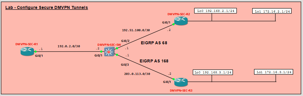
Addressing Table
|
Device |
Interface |
IPv4 Address |
|---|---|---|
|
DMVPN-SEC-R1 |
Gi0/1 |
192.0.2.1/30 |
|
Tunnel1 |
100.100.100.1/29 |
|
|
DMVPN-SEC-R2 |
Gi0/1 |
198.51.100.2/30 |
|
Loopback0 |
192.168.2.1/24 |
|
|
Loopback1 |
172.16.2.1/24 |
|
|
Tunnel1 |
100.100.100.2/29 |
|
|
DMVPN-SEC-R3 |
Gi0/1 |
203.0.113.2/30 |
|
Loopback0 |
192.168.3.1/24 |
|
|
Loopback1 |
172.16.3.1/24 |
|
|
Tunnel1 |
100.100.100.3/29 |
|
|
DMVPN-SEC-SW |
Gi0/1 |
192.0.2.2/30 |
|
Gi0/2 |
198.51.100.1/30 |
|
|
Gi0/3 |
203.0.113.1/30 |
Observación: La tabla de la página 1 del PDF contiene una discrepancia para Loopback0 de R
Objectives
- Part 1: Build the Network and Verify DMVPN Phase 3 Operation
- Part 2: Secure DMVPN Phase 3 Tunnels
Background / Scenario
In previous labs, you have configured DMVPN Phase 1 and Phase 3 networks, including configuration of DMVPN Phase 3 with IPv6. However, in those labs, IPsec was not used to encrypt and protect data travelling on the tunnels. IPsec functionality is essential to DMVPN implementation. In this lab, you will work with the DMVPN Phase 3 implementation from the Implement a DMVPN Phase 3 Spoke-to-Spoke Topology lab. You will start with a working configuration and then apply IPsec to the spoke-to-hub and spoke-to-spoke tunnels. Finally, you will verify the operation of the secured tunnels.
Required Resources - Sergio Jiménez's Version
For this lab I am using GNS3, where I have deployed:
- 3 Routers (Cisco IOSv)
- 1 Switch (Cisco IOSvL2)
Instructions
Part 1: Configure Basic Device Settings and Verify Connectivity and DMVPN
These are the final configurations from the “Lab - Implement a DMVPN Phase 3 Spoke-to-Spoke Topology.” If you do not have preconfigured devices from that lab, paste in these initial configurations into the devices before proceeding to Part 1.
DMVPN-SEC-R1 (Hub Router)
conf t
hostname DMVPN-SEC-R1
no ip domain lookup
banner motd # DMVPN-SEC-R1, Implement DMVPN Hub #
line con 0
 exec-timeout 0 0
 logging synchronous
exit
line vty 0 4
 privilege level 15
 password cisco123
 exec-timeout 0 0
 logging synchronous
 login
exit
interface GigabitEthernet0/1
 ip address 192.0.2.1 255.255.255.252
 no shutdown
exit
interface Tunnel1
 tunnel mode gre multipoint
 tunnel source GigabitEthernet0/1
 tunnel key 999
 ip address 100.100.100.1 255.255.255.248
 ip nhrp network-id 1
 ip nhrp authentication NHRPauth
 ip nhrp map multicast dynamic
 ip nhrp redirect
 bandwidth 4000
 ip mtu 1400
 ip tcp adjust-mss 1360
exit
router eigrp DMVPN_TUNNEL_NET
 address-family ipv4 unicast autonomous-system 68
  eigrp router-id 1.1.1.1
  network 100.100.100.0 255.255.255.248
  af-interface Tunnel1
   no split-horizon
  exit-af-interface
 exit-address-family
exit
router eigrp DMVPN_TRANS_NET
 address-family ipv4 unicast autonomous-system 168
  eigrp router-id 10.1.1.1
  network 192.0.2.0 255.255.255.252
 exit-address-family
exit
end
wr mem
!
DMVPN-SEC-R2 (Spoke 1)
conf t
hostname DMVPN-SEC-R2
no ip domain lookup
banner motd # DMVPN-SEC-R2, Implement DMVPN Spoke 1 #
line con 0
 exec-timeout 0 0
 logging synchronous
exit
line vty 0 4
 privilege level 15
 password cisco123
 exec-timeout 0 0
 logging synchronous
 login
exit
interface GigabitEthernet0/1
 ip address 198.51.100.2 255.255.255.252
 no shutdown
exit
interface Loopback0
 ip address 192.168.2.1 255.255.255.0
 no shutdown
exit
interface Loopback1
 ip address 172.16.2.1 255.255.255.0
 no shutdown
exit
interface Tunnel1
 tunnel mode gre multipoint
 tunnel source Loopback0
 no tunnel destination
 tunnel key 999
 ip address 100.100.100.2 255.255.255.248
 ip nhrp network-id 1
 ip nhrp authentication NHRPauth
 ip nhrp nhs 100.100.100.1
 ip nhrp map multicast 192.0.2.1
 ip nhrp map 100.100.100.1 192.0.2.1
 ip nhrp shortcut
 ip mtu 1400
 ip tcp adjust-mss 1360
exit
router eigrp DMVPN_TUNNEL_NET
 address-family ipv4 unicast autonomous-system 68
  eigrp router-id 2.2.2.2
  network 100.100.100.0 255.255.255.248
  network 172.16.2.0 255.255.255.0
  eigrp stub connected
 exit-address-family
exit
router eigrp DMVPN_TRANS_NET
 address-family ipv4 unicast autonomous-system 168
  eigrp router-id 20.2.2.2
  network 198.51.100.0 255.255.255.252
  network 192.168.2.0 255.255.255.0
 exit-address-family
exit
end
wr mem
!
DMVPN-SEC-R3 (Spoke 2)
conf t
hostname DMVPN-SEC-R3
no ip domain lookup
banner motd # DMVPN-SEC-R3, Implement DMVPN Spoke 2 #
line con 0
 exec-timeout 0 0
 logging synchronous
exit
line vty 0 4
 privilege level 15
 password cisco123
 exec-timeout 0 0
 logging synchronous
 login
exit
interface GigabitEthernet0/1
 ip address 203.0.113.2 255.255.255.252
 no shutdown
exit
interface Loopback0
 ip address 192.168.3.1 255.255.255.0
 no shutdown
exit
interface Loopback1
 ip address 172.16.3.1 255.255.255.0
 no shutdown
exit
interface Tunnel1
 tunnel mode gre multipoint
 tunnel source Loopback0
 no tunnel destination
 tunnel key 999
 ip address 100.100.100.3 255.255.255.248
 ip nhrp network-id 1
 ip nhrp authentication NHRPauth
 ip nhrp nhs 100.100.100.1
 ip nhrp map multicast 192.0.2.1
 ip nhrp map 100.100.100.1 192.0.2.1
 ip nhrp shortcut
 ip mtu 1400
 ip tcp adjust-mss 1360
exit
router eigrp DMVPN_TUNNEL_NET
 address-family ipv4 unicast autonomous-system 68
  eigrp router-id 3.3.3.3
  network 100.100.100.0 255.255.255.248
  network 172.16.3.0 255.255.255.0
  eigrp stub connected
 exit-address-family
exit
router eigrp DMVPN_TRANS_NET
 address-family ipv4 unicast autonomous-system 168
  eigrp router-id 30.3.3.3
  network 203.0.113.0 255.255.255.252
  network 192.168.3.0 255.255.255.0
  eigrp stub connected
 exit-address-family
exit
end
wr mem
!
DMVPN-SEC-SW (Layer 3 Switch)
conf t
hostname DMVPN-SEC-SW
no ip domain lookup
ip routing
banner motd # DMVPN-SEC-SW, DMVPN cloud switch #
line con 0
 exec-timeout 0 0
 logging synchronous
exit
line vty 0 4
 privilege level 15
 password cisco123
 exec-timeout 0 0
 logging synchronous
 login
exit
interface GigabitEthernet0/1
 no switchport
 ip address 192.0.2.2 255.255.255.252
 no shutdown
exit
interface GigabitEthernet0/2
 no switchport
 ip address 198.51.100.1 255.255.255.252
 no shutdown
exit
interface GigabitEthernet0/3
 no switchport
 ip address 203.0.113.1 255.255.255.252
 no shutdown
exit
router eigrp DMVPN_TRANS_NET
 address-family ipv4 unicast autonomous-system 168
  eigrp router-id 40.4.4.4
  network 192.0.2.0 255.255.255.252
  network 198.51.100.0 255.255.255.252
  network 203.0.113.0 255.255.255.252
 exit-address-family
exit
end
wr mem
!
From R1, ping the loopback interfaces of R2 and R3. All pings should be successful. This verifies that full connectivity exists in the underlay, or transport, network.
Return to R2. Initiate a traceroute to the simulated LAN interface on R3. The path will pass through R1 as it does in a DMVPN Phase 1 network. Note: The first trace may fail if the DMVPN switch CAM table is empty.
Issue the traceroute command again. You will now see that R1 has enabled direct spoke-to-spoke communication between R2 and R3. This tunnel will expire and close dynamically. The tunnel reopens after data for the spoke router is sent again.
Part 2: Secure DMVPN Phase 3 Tunnels
Now that the tunnels have been configured and DMVPN connectivity has been verified, the tunnels can be secured with IPsec.
Step 1: Create the IKE policy.
Create an IKE policy that defines the hash algorithm, encryption type, key exchange method, Diffie-Hellman group, and the authentication method.
Step 2: Configure the ISAKMP key.
Configure the pre-shared key and peer address. Use 0.0.0.0 to match multiple peer addresses. Use a key of DMVPN@key#.
Step 3: Create and configure the IPsec transform set.
Configure the IPsec transform set. Use DMVPN_TRANS as the transform set name. Specify esp-aes with a 256-bit key as the encryption transform and esp-sha384-hmac as the authentication transform. Configure the transform set to use IPsec transport mode for the tunnels.
Step 4: Create the IPsec profile.
Create an IPsec profile with the name DMVPN_PROFILE. Associate the DMVPN_TRANS transform set with the profile.
Step 5: Apply the IPsec profile to the tunnel interface.
Finally, apply the IPsec profile to the tunnel interface. After you apply the profile, you will see the that IPsec is now active and you will lose adjacency with R2 and R3 until their respective ends of the tunnel are configured.
Step 6: Configure R2 and R3 with IPsec.
Repeat this configuration on the R2 and R3 routers.
Step 7: Verify DMVPN Phase 3 operation.
- As was done previously, test the operation of the spoke-to-spoke DMVPN. Return to R2. Initiate a traceroute to the simulated LAN interface on R3. The path will pass through R1 as it does in a DMVPN Phase 1 network.
- Issue the traceroute command again. You will now see that R1 has enabled direct spoke-to-spoke communication between R2 and R3. This tunnel will expire and close dynamically. The tunnel reopens after data for the spoke router is sent again.
Step 8: Verify IPsec configuration.
Note: Shut down a tunnel interface to clear its IPsec socket if you wish to explore the outputs before and after spoke-to-spoke tunnel establishment.
- To show information about the IPsec profiles that are configured on a device, issue the show crypto ipsec profile command. Note that the profile that was previously configured is shown along with a default profile.
- It is very important to verify that tunnel traffic will be encrypted. On R1, issue the show dmvpn detail command. As the hub router, R1 should see the spoke peers. The first part of the output shows the tunnel interface status and the peer table. Both peers should be shown with their transport and overlay interface addresses, as you have seen previously.
The Crypto Session Details portion of the output should contain information about the status of the encrypted tunnels. Both of the spoke routers should appear in this output also. Note that the transform set that you configured is also displayed in the Crypto Session output. - Issue the show crypto ipsec sa command on R2 to display the security associations (sa) that have been made by R2. This output is for the spoke-to-hub tunnel between R1 and R2 prior to the establishment of the spoke-to-spoke tunnel. This command provides additional details regarding the IPsec status of the tunnel, encrypted and decrypted packet statistics, and other details regarding characteristics of the encrypted tunnel.
- The output below is for the same command after the spoke-to-spoke tunnel is open. Entries exist for both the tunnel to R1 and the spoke-to-spoke tunnel between R2 and R3.
- On R2 issue the show crypto isakmp sa command to view the Internet Security Association Management Protocol (ISAKMP) SAs between the peers. Before the formation of the spoke-to-spoke tunnel, SAs were made between R2 and R3, but no further negotiations have occurred, as indicated by the MM_NO_STATE state of the two SAs between the routers.
After traffic has established the spoke-to-spoke tunnel, the SAs all show the QM_IDLE state. The SAs have been fully negotiated and are available for further ISAKMP quick mode exchanges.
Note: ISAKMP modes are outside the scope of this course. - You have successfully configured and verified IPsec on DMVPN Phase 3 tunnels.