
Lab - Implement BGP Path Manipulation
Topology
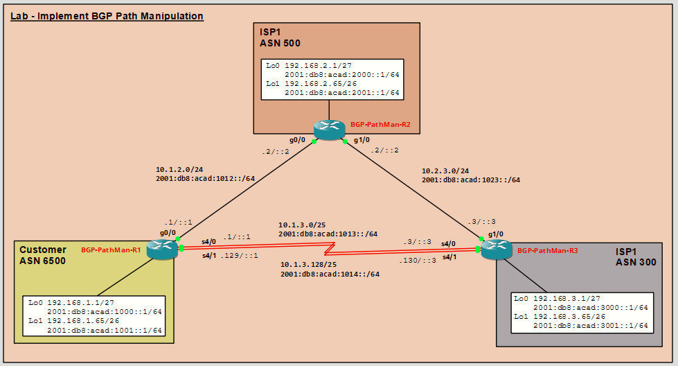
Addressing Table
|
Device |
Interface |
IPv4 Address |
IPv6 Address |
IPv6 Link-Local |
|---|---|---|---|---|
|
BGP-PathMan-R1 |
G0/0 |
10.1.2.1/24 |
2001:db8:acad:1012::1/64 |
fe80::1:1 |
|
S4/0 |
10.1.3.1/25 |
2001:db8:acad:1013::1/64 |
fe80::1:2 |
|
|
S4/1 |
10.1.3.129/25 |
2001:db8:acad:1014::1/64 |
fe80::1:3 |
|
|
Loopback0 |
192.168.1.1/27 |
2001:db8:acad:1000::1/64 |
fe80::1:4 |
|
|
Loopback1 |
192.168.1.65/26 |
2001:db8:acad:1001::1/64 |
fe80::1:5 |
|
|
BGP-PathMan-R2 |
G0/0 |
10.1.2.2/24 |
2001:db8:acad:1012::2/64 |
fe80::2:1 |
|
G1/0 |
10.2.3.2/24 |
2001:db8:acad:1023::2/64 |
fe80::2:2 |
|
|
Loopback0 |
192.168.2.1/27 |
2001:db8:acad:2000::1/64 |
fe80::2:3 |
|
|
Loopback1 |
192.168.2.65/26 |
2001:db8:acad:2001::1/64 |
fe80::2:4 |
|
|
BGP-PathMan-R3 |
G1/0 |
10.2.3.3/24 |
2001:db8:acad:1023::3/64 |
fe80::3:1 |
|
S4/0 |
10.1.3.3/25 |
2001:db8:acad:1013::3/64 |
fe80::3:2 |
|
|
S4/1 |
10.1.3.130/25 |
2001:db8:acad:1014::3/64 |
fe80::3:3 |
|
|
Loopback0 |
192.168.3.1/27 |
2001:db8:acad:3000::1/64 |
fe80::3:4 |
|
|
Loopback1 |
192.168.3.65/26 |
2001:db8:acad:3001::1/64 |
fe80::3:5 |
Objectives
In this lab, you will learn how to use policy-based routing to influence path section.
- Part 1: Configure Basic Device Settings and Interface Addressing
- Part 2: Configure and Verify Multi-Protocol BGP on all Routers
- Part 3: Configure and Verify BGP Path Manipulation Settings on all Routers
Background / Scenario
The default settings in BGP allow for a great deal of undesired route information to pass between autonomous systems. In this lab you will configure Multi-Protocol BGP and implement various path manipulation options for both IPv4 and IPv6.
Note: This lab is an exercise in developing, deploying, and verifying various path manipulation tools for BGP, and does not reflect networking best practices.
Required Resources - Sergio Jiménez's Version
For this lab I am using GNS3, where I have deployed:
- 3 Routers (Cisco 7200)
Instructions
Part 1: Configure Basic Device Settings and Interface Addressing
BGP-PathMan-R1
conf t
no ip domain lookup
hostname BGP-PathMan-R1
line con 0
 exec-timeout 0 0
 logging synchronous
banner motd # This is BGP-PathMan-R1, BGP Path Manipulation Lab #
ipv6 unicast-routing
interface g0/0
 ip address 10.1.2.1 255.255.255.0
 ipv6 address fe80::1:1 link-local
 ipv6 address 2001:db8:acad:1012::1/64
 no shutdown
interface s4/0
 ip address 10.1.3.1 255.255.255.128
 ipv6 address fe80::1:2 link-local
 ipv6 address 2001:db8:acad:1013::1/64
 no shutdown
interface s4/1
 ip address 10.1.3.129 255.255.255.128
 ipv6 address fe80::1:3 link-local
 ipv6 address 2001:db8:acad:1014::1/64
 no shutdown
interface loopback 0
 ip address 192.168.1.1 255.255.255.224
 ipv6 address fe80::1:4 link-local
 ipv6 address 2001:db8:acad:1000::1/64
 no shutdown
interface loopback 1
 ip address 192.168.1.65 255.255.255.192
 ipv6 address fe80::1:5 link-local
 ipv6 address 2001:db8:acad:1001::1/64
 no shutdown
end
wr mem
!
BGP-PathMan-R2
conf t
no ip domain lookup
hostname BGP-PathMan-R2
line con 0
 exec-timeout 0 0
 logging synchronous
banner motd # This is BGP-PathMan-R2, BGP Path Manipulation Lab #
ipv6 unicast-routing
interface g0/0
 ip address 10.1.2.2 255.255.255.0
 ipv6 address fe80::2:1 link-local
 ipv6 address 2001:db8:acad:1012::2/64
 no shutdown
interface g1/0
 ip address 10.2.3.2 255.255.255.0
 ipv6 address fe80::2:2 link-local
 ipv6 address 2001:db8:acad:1023::2/64
 no shutdown
interface loopback 0
 ip address 192.168.2.1 255.255.255.224
 ipv6 address fe80::2:3 link-local
 ipv6 address 2001:db8:acad:2000::1/64
 no shutdown
interface loopback 1
 ip address 192.168.2.65 255.255.255.192
 ipv6 address fe80::2:4 link-local
 ipv6 address 2001:db8:acad:2001::1/64
 no shutdown
end
wr mem
!
BGP-PathMan-R3
conf t
no ip domain lookup
hostname BGP-PathMan-R3
line con 0
 exec-timeout 0 0
 logging synchronous
banner motd # This is BGP-PathMan-R3, BGP Path Manipulation Lab #
ipv6 unicast-routing
interface g1/0
 ip address 10.2.3.3 255.255.255.0
 ipv6 address fe80::3:1 link-local
 ipv6 address 2001:db8:acad:1023::3/64
 no shutdown
interface s4/0
 ip address 10.1.3.3 255.255.255.128
 ipv6 address fe80::3:2 link-local
 ipv6 address 2001:db8:acad:1013::3/64
 no shutdown
interface s4/1
 ip address 10.1.3.130 255.255.255.128
 ipv6 address fe80::3:3 link-local
 ipv6 address 2001:db8:acad:1014::3/64
 no shutdown
interface loopback 0
 ip address 192.168.3.1 255.255.255.224
 ipv6 address fe80::3:4 link-local
 ipv6 address 2001:db8:acad:3000::1/64
 no shutdown
interface loopback 1
 ip address 192.168.3.65 255.255.255.192
 ipv6 address fe80::3:5 link-local
 ipv6 address 2001:db8:acad:3001::1/64
 no shutdown
end
wr mem
!
Part 2: Configure and Verify Multi-Protocol BGP on all Routers
In Part 2, you will configure and verify Multi-Protocol BGP on all routers to achieve full connectivity between the routers. The text below provides you with the complete configuration for R1. You will use this to inform your configuration of R2 and R3. The configuration being used here is not meant to represent best practice, but to assess your ability to complete the required configurations.
Step 1: On R1, create the core BGP configuration.
- Enter BGP configuration mode from global configuration mode, specifying AS 6500
- Configure the BGP router-id for R1.
- Disable the default IPv4 unicast address family behavior.
- Based on the topology diagram, configure all the designated neighbors for R1.
Step 2: On R1, configure the IPv4 unicast address family.
- Enter the IPv4 unicast address family configuration mode.
- Configure network statements for the IPv4 networks attached to interfaces loopback0 and loopback1. Remember that BGP does not work the same way that an IGP does, and that the network statement has no impact on neighbor adjacency; it is used solely for advertising purposes.
- Deactivate the IPv6 neighbors and activate the IPv4 neighbors.
Step 3: On R1, configure the IPv6 unicast address family.
- Enter the IPv6 unicast address family configuration mode.
- Configure network statements for the IPv6 networks that are attached to interfaces loopback0 and loopback1. Remember that BGP does not work the same way that an IGP does; therefore, the network statement has no impact on neighbor adjacency; it is used solely for advertising purposes.
- Activate the IPv6 neighbors that are configured for BGP.
Step 4: Configure MP-BGP on R2 and R3 as you did in the previous step.
Step 5: Verify that MP-BGP is operational.
- Use the show bgp ipv4 unicast summary and show bgp ipv6 unicast summary commands to verify that BGP has established three IPv4 and three IPv6 adjacencies and received four prefixes from each neighbor.
- Use the show bgp ipv4 unicast and show bgp ipv6 unicast commands to view the specified BGP tables. Note that R1 has multiple paths to each destination network. Take note of the next hop address for the destination networks marked with the “>” symbol.
- Use the show ip route bgp and show ipv6 route bgp commands to view the routing tables. Note that there is only one route to each destination, and that the routes included in the routing table have the same next hop as those with the “>” symbol in the BGP tables.
Part 3: Configure and Verify BGP Path Manipulation Settings on all Routers
In Part 3, you will configure path manipulation tools for BGP. The way these tools are being used here is not meant to represent best practice, but to assess your ability to complete the required configurations.
Step 1: Configure ACL-based route filtering.
In this step, you will configure R3 so that it only sends ASN300 networks to R1; it will not tell R1 that it knows about the networks in ASN200.
- On R1, issue the command show bgp ipv4 unicast | i 300 to see what prefixes ASN300 is sharing via BGP. Take note of those prefixes that do not originate in ASN300.
- On R3, configure an access list designed to match the source address and mask of the networks belonging to ASN300:
- On R3, apply the ALLOWED_TO_R1 ACL as a distribute list to the IPv4 neighbor adjacencies with R1.
- Perform a reset of the IPv4 adjacency with R1 for the outbound traffic without tearing down the session.
- On R1, issue the command show bgp ipv4 unicast | i 300 to see what prefixes routes ASN300 is now sharing via BGP. All of the prefixes should now originate in ASN300:
Step 2: Configure prefix-list-based route filtering.
In this step, you will configure R1 so that it only accepts ASN500 networks from R2; it will not accept information about ASN300 networks from R2.
- On R1, issue the command show bgp ipv4 unicast | begin 192.168.3 to see what prefixes ASN500 is sharing via BGP. Take note of those prefixes that do not originate in ASN500.
- On R1, configure a prefix list designed to match the source address and mask of networks belonging to ASN500.
- Apply the ALLOWED_FROM_R2 prefix list to the IPv4 neighbor adjacencies for R2.
- Perform a reset of the IPv4 adjacency with R2 for the inbound traffic without tearing down the session.
- On R1, issue the command show bgp ipv4 unicast | i 500 to see what prefixes routes ASN500 is now sharing via BGP. All of the prefixes should now originate in ASN500.
Step 3: Configure an AS-PATH ACL to filter routes being advertised.
In this step, you will configure R1 so that it only sends ASN100 networks to R2; it will not forward information about prefixes from any other ASN to ASN500.
- On R2, issue the command show bgp ipv4 unicast | begin Network to see what prefixes ASN6500 is sharing via BGP. Take note of those prefixes that do not originate in ASN6500. Advertising these routes could set ASN6500 up as a transit AS, and that is not a desirable scenario.
- On R1, configure AS-PATH ACL to match the routes from the local ASN.
- On R1, apply the AS-PATH ACL as a filter-list on the adjacency configured with R2.
- On R1, perform a reset of the IPv4 adjacency with R2 for the outbound traffic without tearing down the session.
- On R2, issue the command show bgp ipv4 unicast | i 6500 to see what prefixes routes ASN6500 is now sharing via BGP. All of the prefixes should now originate in ASN6500.
Step 4: Configure IPv6 prefix-list-based route filtering.
In this step, you will configure R1 so that it only accepts ASN500 IPv6 networks from R2. It will not accept information about ASN300 IPv6 networks from R2.
- On R1, issue the command show bgp ipv6 unicast neighbors 2001:db8:acad:1012::2 routes to see what IPv6 prefixes ASN500 is sharing via BGP. Take note of those IPv6 prefixes that do not originate in ASN500.
- On R1, configure an IPv6 prefix list designed to match the source address and mask of networks belonging to ASN500.
- Apply the IPV6_ALLOWED_FROM_R2 prefix list to the IPv6 neighbor adjacencies for R2.
- Perform a reset of the IPv6 adjacency with R2 for the inbound traffic without tearing down the session.
- On R1, issue the command show bgp ipv6 unicast neighbors 2001:db8:acad:1012::2 routes to see what IPv6 prefixes routes ASN500 is now sharing via BGP. All of the IPv6 prefixes should now originate in ASN500.
- Configure and apply an IPv6 filter to do the same thing on the adjacency with ASN300.
Step 5: Configure BGP path attribute manipulation to effect routing.
In this step, you will configure R1 so that it prefers the next-hop address of 192.168.3.130 over 192.168.3.3, which would normally be the preferred path to ASN300 networks. You will do this by using a prefix list to identify the destination networks and then use a route map to match the prefix list and set the matched networks to have a local preference of 250.
- On R1, issue the command show ip route bgp and take note of the next hop addresses for the 192.168.3.0/27 and 192.168.3.64/26 networks. Then issue the command show bpg ipv4 unicast and note that the 10.1.3.130 is a valid next hop (It’s just not the best next hop, according to the BGP path selection algorithm.) Lastly, issue the command show bgp ipv4 unicast 192.168.3.0 to see details about all the paths available and which one was selected.
- On R1, configure a prefix list designed to match the source address and mask of networks belonging to ASN300.
- Create a route-map named USE_THIS_PATH_FOR_IPV4 that matches on the prefix list you just created and sets the local preference to 250.
- Next, apply this route map to the BGP neighbor 10.1.3.130.
- Perform a reset of the IPv4 adjacency with R3 for the inbound traffic without tearing down the session.
- On R1, issue the command show ip route bgp and take note of the next hop addresses for the 192.168.3.0/27 and 192.168.3.64/26 networks; it should be 10.1.3.130 for both. Issue the command show bgp ipv4 unicast and you should see the local preference value in the appropriate column.
Note: It may take a bit for the RIB to refresh with updated information.