
Lab – Implement eBGP and iBGP
Topology
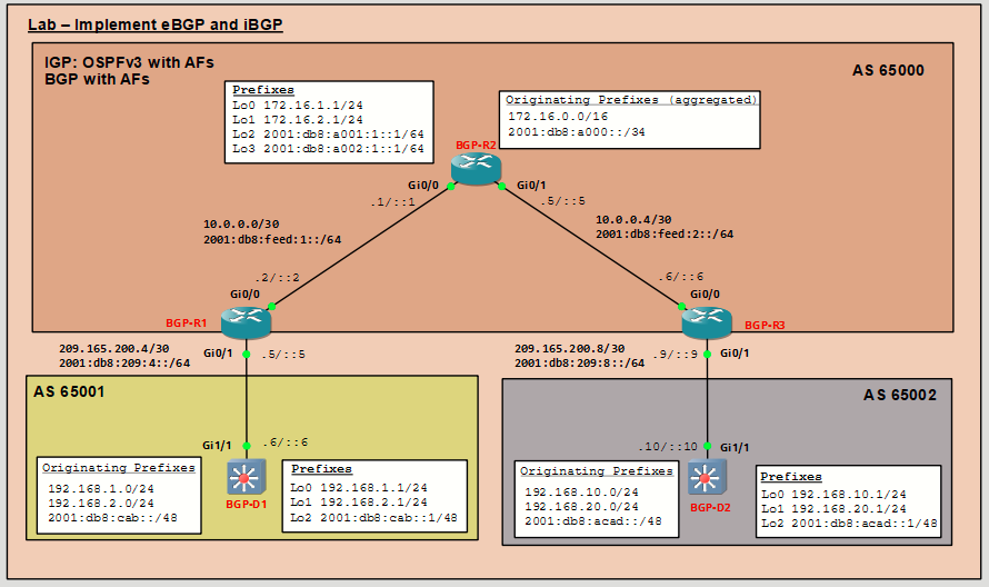
Addressing Table
|
Device |
Interface |
IPv4 Address |
IPv6 Address |
IPv6 Link-Local |
|---|---|---|---|---|
|
BGP-R1 |
Gi0/0 |
10.0.0.2/30 |
2001:db8:feed:1::2/64 |
fe80::1:1 |
|
Gi0/1 |
209.165.200.5/30 |
2001:db8:209:4::5/64 |
fe80::1:2 |
|
|
BGP-R2 |
Gi0/0 |
10.0.0.1/30 |
2001:db8:feed:1::1/64 |
fe80::2:1 |
|
Gi0/1 |
10.0.0.5/30 |
2001:db8:feed:2::5/64 |
fe80::2:2 |
|
|
Lo0 |
172.16.1.1/24 |
N/A |
N/A |
|
|
Lo1 |
172.16.2.1/24 |
N/A |
N/A |
|
|
Lo2 |
N/A |
2001:db8:a001:1::1/64 |
EUI-64 |
|
|
Lo3 |
N/A |
2001:db8:a002:1::1/64 |
EUI-64 |
|
|
BGP-R3 |
Gi0/0 |
10.0.0.6/30 |
2001:db8:feed:2::6/64 |
fe80::3:1 |
|
Gi0/1 |
209.165.200.9/30 |
2001:db8:209:8::9/64 |
fe80::3:2 |
|
|
BGP-D1 |
Gi1/1 |
209.165.200.6/30 |
2001:db8:209:4::6/64 |
fe80::d1:1 |
|
Lo0 |
192.168.1.1/24 |
N/A |
N/A |
|
|
Lo1 |
192.168.2.1/24 |
N/A |
N/A |
|
|
Lo2 |
N/A |
2001:db8:cab::1/48 |
EUI-64 |
|
|
BGP-D2 |
Gi1/1 |
209.165.200.10/30 |
2001:db8:209:8::10/64 |
fe80::d2:1 |
|
Lo0 |
192.168.10.1/24 |
N/A |
N/A |
|
|
Lo1 |
192.168.20.1/24 |
N/A |
N/A |
|
|
Lo2 |
N/A |
2001:db8:acad::1/48 |
EUI-64 |
Objectives
In this lab, you will learn how to use policy-based routing to influence path section.
- Part 1: Build the Topology and Configure Basic Device Settings and IP Addressing
- Part 2: Configure eBGP Edge Routers
- Part 3: Configure iBGP on AS 65000 Routers
- Part 4: Verify iBGP and eBGP Reachability
- Part 5: Configure AS 65000 as a Non-Transit AS
Background / Scenario
In this lab, AS 65000 uses OSPFv3 as its Interior Gateway Protocol (IGP) to provide internal reachability for both IPv4 and IPv6. OSPFv3 is configured with separate address families, allowing a single IGP to support dual-stack operation. Loopback interfaces are used to represent internal IPv4 and IPv6 prefixes within AS 65000; these prefixes simulate customer or internal networks and are later advertised into BGP.
AS 65000 runs BGP using address families (AFs) for both IPv4 and IPv6, enabling a unified BGP process to handle dual-stack routing. External autonomous systems AS 65001 and AS 65002 use traditional BGP for IPv4 and the IPv6 unicast address family for IPv6. Because IPv6 routing in BGP is supported only through address families, all IPv6 BGP configuration and route exchange in this lab occurs within the IPv6 AF context.
This design reflects modern dual-stack enterprise and service provider networks, where an IGP such as OSPFv3 provides internal reachability while BGP, using address families, controls inter-AS routing and policy.
Note: Although the BGP standards (e.g., RFC 4271) define the abbreviations as EBGP and IBGP, modern vendor documentation often uses the lower-case forms eBGP and iBGP to visually distinguish “external” or “internal” from the core BGP protocol name. We will use lower case e and i to make it easier to visually distinguish these two protocols.
Required Resources - Sergio Jiménez's Version
For this lab I am using GNS3, where I have deployed:
- 3 Routers (Cisco IOSv)
- 2 Switches (Cisco IOSvL2)
Instructions
Part 1: Configure Basic Device Settings and Verify Connectivity and DMVPN
BGP-R1
conf t
hostname BGP-R1
no ip domain lookup
line con 0
 exec-timeout 0 0
 logging sync
ipv6 unicast-routing
router ospfv3 1
 address-family ipv4 unicast
  router-id 1.1.1.1
 exit-address-family
 address-family ipv6 unicast
  router-id 1.1.1.1
 exit-address-family
interface GigabitEthernet0/0
 ip address 10.0.0.2 255.255.255.252
 ipv6 address 2001:db8:feed:1::2/64
 ipv6 address fe80::1:1 link-local
 ospfv3 network point-to-point
 ospfv3 1 ipv6 area 0
 ospfv3 1 ipv4 area 0
 no shutdown
exit
interface GigabitEthernet0/1
 ip address 209.165.200.5 255.255.255.252
 ipv6 address 2001:db8:209:4::5/64
 ipv6 address fe80::1:2 link-local
 no shutdown
exit
end
wr mem
!
BGP-R2
conf t
hostname BGP-R2
no ip domain lookup
line con 0
 exec-timeout 0 0
 logging sync
ipv6 unicast-routing
router ospfv3 1
 address-family ipv4 unicast
  router-id 2.2.2.2
 exit-address-family
 address-family ipv6 unicast
  router-id 2.2.2.2
 exit-address-family
interface GigabitEthernet0/0
 ip address 10.0.0.1 255.255.255.252
 ipv6 address 2001:db8:feed:1::1/64
 ipv6 address fe80::2:1 link-local
 ospfv3 network point-to-point
 ospfv3 1 ipv6 area 0
 ospfv3 1 ipv4 area 0
 no shutdown
exit
interface GigabitEthernet0/1
 ip address 10.0.0.5 255.255.255.252
 ipv6 address 2001:db8:feed:2::5/64
 ipv6 address fe80::2:2 link-local
 ospfv3 network point-to-point
 ospfv3 1 ipv6 area 0
 ospfv3 1 ipv4 area 0
 no shutdown
exit
interface loopback0
 ip address 172.16.1.1 255.255.255.0
 ipv6 enable
 ospfv3 1 ipv4 area 0
 ospfv3 network point-to-point
 no shutdown
exit
interface loopback1
 ip address 172.16.2.1 255.255.255.0
 ipv6 enable
 ospfv3 1 ipv4 area 0
 ospfv3 network point-to-point
 no shutdown
exit
interface loopback2
 ipv6 address 2001:db8:a001:1::1/64
 ospfv3 1 ipv6 area 0
 ospfv3 network point-to-point
 no shutdown
exit
interface loopback3
 ipv6 address 2001:db8:a002:1::1/64
 ospfv3 1 ipv6 area 0
 ospfv3 network point-to-point
 no shutdown
exit
end
wr mem
!
BGP-R3
conf t
hostname BGP-R3
no ip domain lookup
line con 0
 exec-timeout 0 0
 logging sync
ip routing
ipv6 unicast-routing
router ospfv3 1
 address-family ipv4 unicast
  router-id 3.3.3.3
 exit-address-family
 address-family ipv6 unicast
  router-id 3.3.3.3
 exit-address-family
interface GigabitEthernet0/0
 ip address 10.0.0.6 255.255.255.252
 ipv6 address 2001:db8:feed:2::6/64
 ipv6 address fe80::3:1 link-local
 ospfv3 network point-to-point
 ospfv3 1 ipv6 area 0
 ospfv3 1 ipv4 area 0
 no shutdown
exit
interface GigabitEthernet0/1
 ip address 209.165.200.9 255.255.255.252
 ipv6 address 2001:db8:209:8::9/64
 ipv6 address fe80::3:2 link-local
 no shutdown
exit
end
wr mem
!
BGP-D1
conf t
hostname BGP-D1
no ip domain lookup
line con 0
 exec-timeout 0 0
 logging sync
ip routing
ipv6 unicast-routing
interface GigabitEthernet1/1
 no switchport
 ip address 209.165.200.6 255.255.255.252
 ipv6 address 2001:db8:209:4::6/64
 ipv6 address fe80::d1:1 link-local
 no shutdown
exit
interface loopback0
 ip address 192.168.1.1 255.255.255.0
 ipv6 enable
 no shutdown
exit
interface loopback1
 ip address 192.168.2.1 255.255.255.0
 ipv6 enable
 no shutdown
exit
interface loopback2
 ipv6 address 2001:db8:cab::1/48
 no shutdown
exit
end
wr mem
!
BGP-D2
conf t
hostname BGP-D2
no ip domain lookup
line con 0
 exec-timeout 0 0
 logging sync
ip routing
ipv6 unicast-routing
interface GigabitEthernet1/1
 no switchport
 ip address 209.165.200.10 255.255.255.252
 ipv6 address 2001:db8:209:8::10/64
 ipv6 address fe80::d2:1 link-local
 no shutdown
exit
interface loopback0
 ip address 192.168.10.1 255.255.255.0
 ipv6 enable
 no shutdown
exit
interface loopback1
 ip address 192.168.20.1 255.255.255.0
 ipv6 enable
 no shutdown
exit
interface loopback2
 ipv6 address 2001:db8:acad::1/48
 no shutdown
exit
end
wr mem
!
Part 2: Configure eBGP on Edge Routers
In this part, you will configure eBGP sessions between R1 and D1, and between R3 and D2. These eBGP adjacencies represent connections between different autonomous systems and allow each edge router in AS 65000 to learn routes originated by its external neighbor. At this stage, only eBGP is configured. No internal BGP (iBGP) sessions exist within AS 65000.
As a result, each edge router will learn routes from its directly connected external AS, but those routes will not be shared across AS 65000. This behavior highlights the fundamental role of eBGP and sets the foundation for understanding why iBGP is required to carry routes within an autonomous system.
Note: The edge routers (R1 and R3) are used only to establish eBGP connectivity and do not originate any BGP routes. Prefix origination and aggregation for AS 65000 will be configured later on R2, an iBGP router, allowing routing policy to be centralized.
Step 1: Configure and verify eBGP on R1 to peer with D1.
- Before configuring BGP, confirm that the interface addressing is correct and you can reach the neighbor using the following commands.
- Enter BGP process for AS 65000. The bgp log-neighbor-changes command enables syslog messages when BGP neighbor adjacencies change state. It is not enabled by default but is commonly configured to aid in troubleshooting.
- Configure the IPv4 and IPv6 eBGP neighbor (global neighbor definition). This defines the neighbor and its remote AS for both address families.
Note: In this lab, some BGP neighbor parameters (such as remote-as) are configured in router BGP configuration mode, while route exchange is controlled by activating the neighbor under each address family. This is a common and valid approach. Alternatively, all neighbor configurations, including remote-as can be done entirely within the address-family itself. Both methods are supported by IOS/IOS-XE and result in the same operational behavior. - Activate the IPv4 neighbor under the IPv4 unicast address family. In BGP with address families, the neighbor is defined first, then activated under the appropriate address family to exchange routes. With AF-based BGP, the neighbor must be activated in the AF to exchange routes.
- Activate the IPv6 neighbor under the IPv6 unicast address family.
- Verify the BGP IPv4 session status. At this point, the BGP session is not established because the remote peer has not yet been configured; BGP sessions require configuration on both routers before adjacencies can form. You’ll likely see the neighbor listed with State = Idle/Active, or no neighbor at all.
- Verify the BGP IPv6 session status. This is the same as BGP IPv4. The BGP session is not established yet because the remote peer has not been configured.
Step 2: Configure and verify eBGP on D1 to peer with R1.
- Enable the BGP process on D1 for AS 65001 and enable syslog messages when BGP neighbor adjacencies change state.
- Configure the IPv4 and IPv6 eBGP neighbor. This defines the neighbor and its remote AS for both address families. Notice the message stating IPv4 adjacency is established with R1. IPv6 adjacency is established later after activating R1 as an IPv6 neighbor.
- Originate the IPv4 prefixes with network statements. These prefixes must exist in D1’s routing table (they are looback addresses on D1).
- Configure the IPv6 eBGP neighbor under the IPv6 address family. IPv6 BGP requires the IPv6 address family. The activate parameter is required to establish IPv6 adjacency with R1 and to exchange IPv6 routes. The IPv6 prefix is originated from D1 using the network command.
- The following output verifies the status of the BGP session between D1 and R1. In the State/PfxRcd column, a numeric value indicates that the BGP session is established, with the number representing how many prefixes have been received from the neighbor rather than showing the word Established. Currently, R1 is not advertising any prefixes.
- The following command displays detailed information about the BGP neighbor relationship and explicitly confirms that the session is in the Established state.
- The output confirms that R1 has an established eBGP session with D1 (AS 65001). The value 2 in the State/PfxRcd column indicates that R1 has successfully received two IPv4 prefixes from its neighbor.
- The following command displays the IPv4 BGP routing table on R1, where you can see the two IPv4 prefixes learned from D1 via eBGP. Both routes are marked as valid and best paths, with D1 shown as the next hop.
- This output confirms that R1 has an established IPv6 eBGP session with D1 (AS 65001). The value 1 in the State/PfxRcd column indicates that R1 has received one IPv6 prefix from its neighbor.
- The following command displays the IPv6 BGP routing table on R1, where you can see the IPv6 prefix learned from D1 via eBGP. The route is marked as valid and best, with D1 shown as the next hop.
- This output verifies that R1 has installed the IPv4 prefixes learned from D1 into its routing table, with both routes marked as BGP-learned and reachable via the eBGP neighbor.
- The IPv6 routing table on R1 shows that the IPv6 prefix advertised by D1 has been successfully installed as a BGP route.
Step 3: Configure and verify eBGP between R3 and D2.
In this step, you will configure the eBGP peering between R3 and D2. Because this configuration closely mirrors the eBGP setup between R1 and D1, the full set of BGP commands are shown for each router without repeating the same step-by-step explanation.
- Before BGP, confirm the interface addressing is correct and you can reach the neighbor using the following commands on R3 and D2:
- Configure eBGP on R3.
- Configure eBGP on D2.
- Verify R3 has an established eBGP session with D2 (AS 65002).
- Verify the IPv4 BGP routing table on R3, where you can see the two IPv4 prefixes learned from D2 via eBGP.
- Verify R3 has an established IPv6 eBGP session with D2 (AS 65002).
- Verify the IPv6 BGP routing table on R3, where you can see the IPv6 prefix learned from D2 via eBGP.
- Verify that R3 has installed the IPv4 prefixes learned from D2 into its routing table.
- The IPv6 routing table on R3 shows that the IPv6 prefix advertised by D2 has been successfully installed as a BGP route.
Part 3: Configure iBGP on AS 65000 Routers
So far, each edge router (R1 and R3) in AS 65000 has learned routes only from its directly connected external neighbor. R1 has not learned any prefixes from AS 65002 and R3 has not learned any prefixes from AS 65001. R2 has not yet been configured for BGP and is not aware of any prefixes outside of AS 65000.
In this part, you will configure full-mesh iBGP between R1, R2, and R3 within AS 65000 so these prefixes (routes) can be exchanged internally between these routers. You will also configure R2 to originate and advertise aggregated IPv4 and IPv6 prefixes, demonstrating how iBGP enables route distribution and centralized policy control within an autonomous system.
Step 1: Configure iBGP on Router R1
- Before configuring iBGP, there should be full IPv4 and IPv6 reachability between all routers in AS 65000 via OSPFv3, as iBGP relies on the IGP to provide next-hop reachability. Verify IGP reachability to the iBGP peers using the following commands.
- Enter the BGP process for AS 65000.
- Configure the IPv4 iBGP neighbors (R2 and R3). These commands define the iBGP peers using their IPv4 interface addresses.
- Activate the IPv4 neighbors (R2 and R3) under the IPv4 unicast address family. With address families, neighbors must be activated under the appropriate AF to exchange routes.
- Configure next-hop-self for iBGP neighbors. R1 is an edge router that learns routes via eBGP from D1. Setting next-hop-self ensures that routes R1 advertises into iBGP use a next hop reachable inside AS 65000. This prevents iBGP peers from receiving routes with an unreachable external next hop.
By using next-hop-self, R1 sets itself as the next hop for routes advertised into iBGP. Because all routers in AS 65000 have full IPv4 and IPv6 reachability through OSPFv3, these next-hop addresses are guaranteed to be reachable by the iBGP peers. - Configure the IPv6 iBGP neighbors (R2 and R3) and activate them under the IPv6 address family. IPv6 BGP is configured under the IPv6 unicast address family. As with the IPv4 address family, within the IPv6 AF neighbors must be activated to exchange routes.
Step 2: Configure iBGP on Router R3
- Similar to what you did on R1, you can verify IGP reachability on R3 to the iBGP peers using the following commands.
- The iBGP configuration on R3 mirrors the configuration on R1 with the primary difference being the neighbor IP addresses used to peer with the other routers in AS 65000. As with R1, R3 establishes iBGP sessions with R2 and the remaining edge router and uses next-hop-self to ensure that routes learned via eBGP are advertised with a next hop reachable through OSPFv3. You should see messages confirming IPv4 and IPv6 adjacency with R1.
Note: If you look at the routing tables, you will notice that R1 has routes to reach AS 65002 and R3 has routes to reach AS 65001. However, because R2 does not yet know about these prefixes, you will not be able to verify connectivity. For example, ping an address in AS 65002 from R1.
Step 3: Configure iBGP on Router R2
In this step, you will configure internal BGP (iBGP) on R2, which serves as an internal router within AS 65000 and does not establish any eBGP sessions. R2 is used as the centralized point to originate the aggregated IPv4 and IPv6 prefixes for AS 65000, demonstrating how route origination and aggregation can be handled internally and then distributed to the edge routers through iBGP.
We also configure full-mesh iBGP within AS 65000 so that all BGP routers in the autonomous system can exchange BGP routing information. Because iBGP routers do not forward BGP updates learned from one iBGP neighbor to another by default, each router must establish an iBGP session with every other BGP router in the AS. By configuring R2 with iBGP sessions to both R1 and R3, AS 65000 will have a complete iBGP mesh, allowing internal distribution of routes learned via eBGP as well as prefixes originated within the AS. If R2 were not configured for iBGP, it would not receive BGP routing information from R1 or R3 and therefore would not be able to forward traffic between them based on BGP-learned routes.
- Enter the BGP process and enable neighbor-change logging.
- Configure the IPv4 iBGP neighbors (R1 and R3). These commands define the iBGP peers using their IPv4 interface addresses:
- Because we are using AF-style BGP, neighbors must be activated under the address family to exchange routes.
Note: R2 is not learning routes from eBGP directly (R1/R3 are), so next-hop-self is typically more important on the edge routers when they pass eBGP-learned routes into iBGP. On R2, it’s optional—use it only if you want to “normalize” next-hop behavior for the routes R2 advertises. - Originate the IPv4 aggregate (summary address) and exit the IPv4 AF.
Note: In this lab, R2 is the single origination point for the aggregated prefixes to simplify the configuration and highlight the role of iBGP. The network 172.16.0.0/16 is an aggregation of all subnets such as Loopback0 172.16.1.0/24 and Loopback1 172.16.2.0/24 networks. In production networks, these summaries are often originated on multiple routers to avoid a single point of failure.
When an AS advertises only an aggregate prefix to its external BGP peers, internal routing changes do not trigger external BGP updates, as long as some route within the aggregate remains reachable. ASN 65000 advertises aggregated prefixes so that internal routing changes do not trigger external BGP updates, which reflects real-world design practices used to improve stability and reduce BGP churn on the Internet. Traffic will be forwarded to AS 65000 and dropped if a prefix is not present. - Configure and activate the IPv6 iBGP neighbors (R1 and R3) under the IPv6 address family. IPv6 BGP is configured under the IPv6 unicast address family. As with the IPv4 address family, within the IPv6 AF neighbors must be activated to exchange routes.
- Originate the IPv6 aggregate 2001:db8:a000::/36 which is a summary for Loopback2 2001:db8:a001::/48 and Loopback3 2001:db8:a002::/48 networks.
- BGP will only advertise a network statement if an exact prefix (prefix and prefix length) exists in the routing table. To ensure 172.16.0.0/16 and 2001:db8:a000::/36 exists in R2’s IPv4/IPv6 routing tables, static routes are configured using Null0 to prevent traffic from being forwarded if no more-specific route exists.
Part 4: Verify iBGP and eBGP Reachability
At this point in the lab, external BGP (eBGP) has been successfully configured on all edge routers and internal BGP (iBGP) has been implemented as a full mesh within AS 65000. The internal router R2 is now originating aggregated IPv4 and IPv6 prefixes, which are distributed to the edge routers and advertised externally.
In this part, you will verify BGP adjacencies, examine BGP tables, and confirm that each AS has learned the appropriate BGP routes. This includes verifying that AS 65001 and AS 65002 have reachability to each other’s prefixes through AS 65000, demonstrating that AS 65000 is currently functioning as a transit autonomous system.
Step 1: Verify AS 65000 reachability via OSPFv3 on R1, R2, and R3.
- The following commands display the IPv4 and IPv6 routes learned via OSPFv3 on R1, verifying that there is full internal reachability within AS 65000, which is required for iBGP next-hop resolution and overall connectivity.
- Use similar commands on R3 to verify the same reachability for R3 within AS 65000.
- R2 does not display any OSPFv3-learned routes because all networks within the OSPFv3 routing domain are directly connected to R2, so there are no remote OSPF routes to install in the routing table.
Step 2: Verify eBGP and iBGP adjacencies on AS 65000 edge routers R1 and R3
- The output confirms that R1 maintains its existing eBGP adjacency with D1 (AS 65001 – 209.165.200.6), and now also has iBGP adjacencies with R2 (10.0.0.1) and R3 (10.0.0.6) within AS 65000. With iBGP fully configured, R1 participates in a full-mesh iBGP topology for both IPv4 and IPv6, allowing routes learned via eBGP to be distributed internally across the autonomous system.
- Use the same BGP verification commands on R3 to confirm that it has established eBGP adjacencies with D2 and iBGP adjacencies with R1 and R2 for both IPv4 and IPv6, completing the full-mesh iBGP topology within AS 65000.
Step 3: Verify eBGP adjacencies on AS 65001 and AS 65002 routers D1 and D2
- The BGP summary output on D1 confirms an established eBGP adjacency with R1 in AS 65000, showing that D1 is successfully exchanging IPv4 and IPv6 routes with AS 65000.
- Use the same commands on D2 to confirm it has established eBGP adjacency with R3 in AS 65000, showing that D2 is successfully exchanging IPv4 and IPv6 routes with AS 65000.
Step 4: Verify BGP tables on AS 65000 routers R1, R2, and R3.
- In this step, we examine the BGP tables on the routers in AS 65000 to verify that routes learned via eBGP and iBGP are present and that next-hop information is being handled correctly. Because AS 65000 is running full-mesh iBGP and OSPFv3 as its IGP, internal next-hop addresses must be reachable through OSPFv3, while external next hops reflect the directly connected eBGP peers. By inspecting the BGP tables, we can see the difference between routes learned via eBGP and those learned via iBGP, as well as how AS 65000 is functioning as a transit AS.
Explaining Specific BGP Entries on R1
R1’s routing table shows BGP routes learned from three different sources.
iBGP route for a prefix originated inside AS 65000
This route represents the aggregated prefix originated by R2 within AS 65000. The i flag indicates the route was learned via iBGP, and the next hop is 10.0.0.1, which is R2’s internal address. Because OSPFv3 provides full reachability within AS 65000, R1 can reach this next hop through the IGP, allowing the route to be installed and used. Under the Path column in the table, the i without an AS_PATH indicates this prefix originated within AS 65000 and has not traversed any external autonomous systems.
iBGP route for a prefix originating in AS 65002
This route was learned via eBGP on R3 from AS 65002 and advertised to R1 using iBGP. The next hop has been rewritten to 10.0.0.6 (R3’s internal address) due to the next-hop-self configuration on the edge router. This ensures that the next hop is reachable inside AS 65000 via OSPFv3. The AS_PATH shows 65002, indicating the route originated in AS 65002 and was learned internally via iBGP after entering AS 65000 through an edge router.
eBGP route learned directly from AS 65001
This route was learned directly via eBGP from D1 in AS 65001. Because it is an eBGP-learned route, the next hop remains the external neighbor’s IP address (209.165.200.6). No i flag is present, indicating this is not an internal BGP route. The AS_PATH shows 65001, indicating the route originated in AS 65001 and was learned internally via iBGP after entering AS 65000 through an edge router. - Examine the BGP IPv6 table on R1 to view similar information as you saw in the BGP IPv4 table.
- The BGP tables on R3 mirror what we observed on R1. Routes originating within AS 65000 and learned via iBGP use internal next hops resolved through OSPFv3, while routes learned directly from AS 65002 via eBGP use the external neighbor as the next hop.
This confirms that iBGP is distributing internal and external routes consistently across AS 65000, with edge routers preserving eBGP next hops and internal routes using IGP-reachable addresses. - Examine the BGP table on R2. R2 operates exclusively as an iBGP router and is responsible for originating the aggregated IPv4 and IPv6 prefixes for AS 65000, which are then distributed to the edge routers via iBGP
On R2, the aggregated prefixes 172.16.0.0/16 (IPv4) and 2001:db8:a000::/36 (IPv6) show a next hop of 0.0.0.0 and :: because these routes are locally originated by R2 using the network command.
In BGP, a next hop of 0.0.0.0 (IPv4) or :: (IPv6) means “this router is the source of the route”, which is also why these entries have the default weight of 32768, a value automatically assigned to locally originated routes.
All other routes in R2’s BGP table are marked as iBGP entries (*>i) and use next hops that are internal AS 65000 addresses (for example, 10.0.0.2 or 10.0.0.6, and their IPv6 equivalents). These next hops point to the edge routers (R1 or R3) that learned the prefixes via eBGP and then advertised them into AS 65000 using iBGP, with reachability provided by the underlying OSPFv3 IGP.
R2 originates and aggregates local prefixes, while edge routers handle eBGP, and iBGP carries reachability across the AS using IGP-resolvable next hops.
Step 5: Verify BGP tables on AS 65000 routers R1, R2. and R3.
In a typical network design, only routers that participate in the BGP transit path need to maintain BGP routing information, whether learned via eBGP or iBGP. Other internal routers, running an IGP such as OSPFv3, do not require full BGP routes and instead forward traffic using a default route or summarized routes toward an ABR or ASBR.
Some routers outside the transit forwarding path may still participate in BGP for control-plane reasons, such as acting as route reflectors, originating prefixes using BGP network statements, or applying routing policy, even if they are not directly forwarding transit traffic
In this lab, AS 65000 functions as a transit AS, so R1, R2, and R3 maintain BGP routes to ensure end-to-end reachability between external autonomous systems.
- The IP routing tables on R1 show only the best BGP routes selected for forwarding. These entries demonstrate how eBGP and iBGP routes are resolved using next-hop reachability provided by OSPFv3, allowing R1 to forward traffic between external autonomous systems while maintaining aggregated routing information for AS 65000.
- Unlike the edge routers, R2 does not maintain any eBGP adjacencies. Instead, it learns all external prefixes via iBGP from R1 and R3. As a result, all BGP routes in R2’s IPv4 and IPv6 routing tables use internal next-hop addresses within AS 65000, confirming that R2 relies on OSPFv3 for next-hop reachability while participating in BGP for control-plane route distribution.
- The BGP routing entries on R3 confirm that, like R1, R3 functions as both an edge and transit router, forwarding traffic between external autonomous systems while relying on iBGP and OSPFv3 for internal reachability.
- The full routing tables on R1 show both OSPF-learned specific routes and BGP-learned aggregated routes for the same address space.
Within AS 65000, OSPFv3 advertises the more specific internal prefixes (such as 172.16.1.0/24, 172.16.2.0/24, and their IPv6 equivalents), while BGP advertises a summarized aggregate prefix (172.16.0.0/16 and 2001:DB8:A000::/36) that represents the entire AS. Because OSPF routes have a lower administrative distance than iBGP-learned routes, the router installs the OSPF routes for internal forwarding, while the BGP aggregate remains present to support inter-AS reachability and policy control.
This behavior allows AS 65000 to use detailed IGP routing internally while presenting a simplified, aggregated view of the network to external autonomous systems.
As an edge eBGP router, R1 advertises only BGP routes to its external neighbor, D1. OSPFv3 routes, while used internally for forwarding, are not advertised across the eBGP boundary
Step 6: Verify BGP tables on AS 65001 and AS 65002 edge routers D1 and D2 .
- The BGP tables on D1 show three distinct types of routes.
- D1’s locally originated prefixes (192.168.1.0/24, 192.168.2.0/24, and 2001:DB8:CAB::/48) appear with a next hop of 0.0.0.0 (or ::) and an empty AS path, indicating that these routes were originated within AS 65001.
- D1 learns the aggregated prefixes from AS 65000 (172.16.0.0/16 and 2001:DB8:A000::/36) via its eBGP neighbor R1, with the AS path showing only 65000 and the next hop pointing to R1.
- D1 receives prefixes from AS 65002 via AS 65000, where the AS path 65000 65002 clearly shows that AS 65000 is acting as a transit AS between AS 65001 and AS 65002.
Note: The presence of the AS path 65000 65002 for prefixes originating in AS 65002 confirms that AS 65000 is acting as a transit AS, carrying traffic between two external autonomous systems rather than only serving its own customers.
- The BGP tables on D2 show a similar pattern to those on D1.
Step 7: Verify BGP table on AS 65001 and AS 65002 edge routers D1 and D2.
- The IP routing tables on D1 confirm reachability to external prefixes learned via BGP. D1 installs the aggregated prefixes from AS 65000 as well as prefixes originating in AS 65002, all reachable via its eBGP neighbor, R1. This verifies that traffic destined for other autonomous systems is successfully forwarded through AS 65000, further confirming that AS 65000 is operating as a transit AS for both IPv4 and IPv6 traffic.
- The IP routing tables on D2 show a similar result to those on D1.
Part 5: Configure AS 65000 as a Non-Transit AS
In BGP, a transit AS provides connectivity between other autonomous systems by advertising routes learned from one AS to another. Up to this point, AS 65000 has been operating as a transit AS. In this part, we will apply a simple BGP policy that prevents AS 65000 from forwarding external routes between AS 65001 and AS 65002, effectively converting it into a non-transit AS.
From the perspective of AS 65001 and AS 65002, the difference between a transit and non-transit AS is reflected in which external prefixes are reachable. When AS 65000 operates as a transit AS, D1 and D2 learn not only AS 65000’s aggregated prefixes but also prefixes originating in the other external AS, allowing end-to-end connectivity between AS 65001 and AS 65002. After AS 65000 is converted to a non-transit AS, D1 and D2 will continue to reach AS 65000’s own prefixes, but routes to the other external AS will no longer be advertised, eliminating inter-AS transit through AS 65000.
Step 1: Create an as-path access list on R1.
Configure the AS-path access list on R1.
This command creates an AS-path access list, which is used by BGP to match routes based on its AS path attribute.
ip as-path access-list 10
- Creates AS-path access list number 10. AS-path access lists are defined in global configuration mode and are later applied to BGP neighbors.
permit
- Allows routes that match the specified AS-path pattern.
^$
- This is a regular expression that matches an empty AS path:
- ^ represents the beginning of the AS path
- $ represents the end of the AS path
- Together, ^$ matches routes that originate locally within the AS, meaning they were generated by AS 65000 itself and have not passed through any other autonomous systems.
This AS-path access list matches only routes originated by AS 65000 and excludes any routes learned from external autonomous systems. When applied to an eBGP neighbor, it ensures that R1 advertises only AS 65000’s own prefixes, which is a key step in preventing AS 65000 from acting as a transit AS.
Step 2: Apply the AS-Path Filter to R1’s eBGP Neighbor
Configure the AS-path filter in both BGP Address Families.
This command applies the AS-path access list 10 to routes advertised outbound to the eBGP neighbor.
neighbor <ip-address> filter-list 10 out
- Ensures the filter affects only routes sent to D1, not routes received from it.
- Because AS-path access list 10 permits only an empty AS path (^$), R1 will now advertise only routes originated by AS 65000 to D1.
- Routes learned via iBGP from AS 65001 or AS 65002 will no longer be advertised to D1.
The configuration is applied separately under both AFs ensuring consistent behavior for both protocol families. This method is used in production networks to prevent unintended transit while preserving customer connectivity.
Step 3: Configure non-transit filtering on R3.
The configuration on R3 mirrors the configuration on R1.
Step 4: Verify BGP Tables After Disabling Transit in AS 65000
- After applying the outbound AS-path filters on R1 and R3, we verify the impact by examining the BGP tables on D1 (AS 65001) and D2 (AS 65002). Notice that D1 no longer has any BGP entries for prefixes originating in AS 65002, confirming that AS 65000 is no longer advertising transit routes.
- You should see similar output for D2.
Step 5: Verify IP Routing Tables After Disabling Transit in AS 65000
- The IP routing tables on D1 confirm that AS 65000 is no longer acting as a transit AS. D1 now installs only the aggregated prefixes originated by AS 65000 in both the IPv4 and IPv6 routing tables. Routes to prefixes originating in AS 65002 are no longer present, demonstrating that traffic destined for other external autonomous systems is no longer forwarded through AS 65000. This verifies that the outbound AS-path filtering on R1 has successfully disabled transit behavior while preserving reachability to AS 65000’s own networks.
- You should see similar output for D2.