
Wireless LANs fundamentals
Wireless LAN Topologies
Wireless communication takes place over free space through the use of RF signals. The transmitter can contact the receiver at any and all times, as long as both devices are turned to the same frequency (or channel) and use the same scheme to carry the data between them.
To fully leverage wireless communication, data should travel in both directions. Because the two devices are using the same channel: take a turn and send at other times.
With wireless communication, if multiple signals are received at the same time, they can interfere with each other. The likelihood of interference increases as the number of wireless devices grows.
IEEE 802.11 WLANs are always half duplex because transmissions between stations use the same frequency or channel. Only one station can transmit at any time; otherwise, collisions occur. To achieve full-duplex mode, one station’s transmission would have to occur on one frequency while it receives over a different frequency—much like full-duplex
Ethernet links work. Although this is certainly possible and practical, the 802.11 standard
does not permit full-duplex operation.
The list of topologies:
Infrastructure mode:
- Basic Service Set
- Distribution System
- Extended Service Set
- Independent Basic Service Set
Non-infrastructure mode:
- Repeater
- Workgroup Bridge
- Outdoor Bridge
- Mesh Network
Basic Service Set

Wireless service area consisting of a closed group of mobile devices that forms around a fixed device. Before a device can participate, it must advertise its capabilities and then be granted permission to join. At the heart of every BSS is a wireless AP. The AP operates in infrastructure mode, which means it offers the services that are necessary to form the infrastructure of a wireless network. The AP also establishes its BSS over a single wireless channel. The AP and the members of the BSS must all use the same channel to communicate properly.
The BSS is bounded by the area where the AP's signal is usable. This is known as the basic service area (BSA) or cell. The AP serves as a single point of contact for every device that wants to use the BSS. It advertises the existence of the BSS so that devices can find it and try to join. To do that, the AP uses a unique BSS identifier (BSSID) that is based on the AP's own radio MAC address.
In addition, the AP advertises the wireless network with a SSID, which is a text string containing a logical name. Think of the BSSID as a machine-readable name tag that uniquely identifies the BSS ambassador (the AP), and the SSID as a nonunique, human-readable name tag that identifies the wireless service.
Understanding the Network Terms SSID, BSSID, and ESSID (Juniper Networks)
Membership with the BSS is called an association. A wireless device must send an association request to the AP and the AP must either grant or deny the request. Once associated, a device becomes a client, or an 802.11 station (STA), of the BSS.
Then, as long as a wireless client remains associated with a BSS, most communications to and from the client must pass through the AP. By using the BSSID as a source or destination address, data frames can be relayed to or from the AP.
Even though data frames are meant to pass through an AP, keep in mind that other devices in the same general area that are listening on the same channel can overhear the transmissions. After all, wireless frames are not contained within a wire that connects a device to an AP. Instead, the frames are freely available over the air to anyone that is within range to receive them. If the frames are unencrypted, then anyone may inspect their contents. Only the BSSID value contained within the frames indicates that the intended sender or recipient is the AP.

Distribution System
An AP can uplink into an Ethernet network because it has both wireless and wired capabilities. The 802.11 standard refers to the upstream wired Ethernet as the distribution system (DS) for the wireless BSS. You can think of an AP as a translational bridge, where frames from two dissimilar media (wireless and wired) are translated and then bridged at L2. In simple terms, the AP is in charge of mapping a VLAN to an SSID.
Example: AP mapping VLAN 10 to the WLAN using SSID "MyNetwork". Clients associated with the "MyNetwork" SSID will appear to be connected to VLAN 10.

This concept can be extended so that multiple VLANs are mapped to multiple SSIDs. To do this, the AP must be connected to the switch by a trunk link that carries the VLANs.

In figure above, VLANS 10, 20 and 30 are trunked to the AP over the DS. The AP uses the 802.1Q tag to map the VLAN numbers to the appropriate SSIDs.
In effect, when an AP uses multiple SSIDs, it is trunking VLANs over the air, and over the same channel, to wireless clients. The clients must use the appropriate SSID that has been mapped to the respective VLAN when the AP was configured. The AP then appears as multiple logical APs (one per BSS) with a unique BSSID for each. With Cisco APs, this is usually accomplished by incrementing the last digit of the radio's MAC address for each SSID.
Extended Service Set
When APs are placed at different geographic locations (ejemplo, una planta de la Torre Picasso), they can all be interconnected by a switched infrastructure. The 802.11 standard calls this an extended service set (ESS).

SSIDs should be defined on all APs. The idea is to make multiple APs cooperate so that the wireless service is consistent and seamless from the client's perspective.
Notice each cell has a unique BSSID, but both cells share one common SSID. Regardless of a client's location within the ESS, the SSID will remain the same but the client can always distinguish one AP from another.
In an ESS, a wireless client can associate with one AP while it is physically located near that AP. If the client later moves to a different location, it can associate with a different nearby AP automatically. Passing from one AP to another is called roaming.
Keep in mind that each AP offers its own BSS on its own channel, to prevent interference between the APs. As a client device roams from one AP to another, it must scan the available channels to find a new AP (and BSS) to roam toward. In effect, the client is roaming from BSS to BSS, and from channel to channel.
Independent Basic Service Set
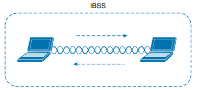
The 802.11 standard allows 2 or more wireless clients to communicate directly with each other, with no other means of network connectivity. This is known as an ad hoc wireless network, or an IBSS. For this to work, one of the devices must take the lead and begin advertising a network name and the necessary radio parameters, much like an AP would do. Any other device can then join as needed. This do not scale well beyond 8-10 devices.
Repeater
Ejemplo: planta de Torre Picasso. Cada AP, normalmente tiene una conexión cableada hacia el DS (switch). Si queremos extender la cobertura, instalamos un nuevo AP y su cableado hacia el switch. No obstante se puede dar la situación en la que instalamos un nuevo AP pero no podemos tirar un cable desde esa ubicación hacia el switch (ya sea por demasiada distancia, etc).
In that case, you can add an additional AP that is configured for repeater mode. A wireless repeater takes the signal it receives and repeats or retransmits it in a new cell area around the repeater. The idea is to move the repeater out away from the AP so that it is still within range of both the AP and the client.
If the repeater has a single transmitter and receiver, it must operate on the same channel that the AP is using. That can create the possibility that the AP's signal will be received and retransmitted by the repeater, only to be received again by the AP (halving the effective throughput because the cannel will be kept busy twice as long as before). As a remedy, some repeaters can use two transmitters and receivers to keep the original and repeated signals isolated on different channels. One transmitter and receiver pair is dedicated to signals in the AP's cell, while the other pair is dedicated to signals in the repeater's own cell.
Workgroup Bridge

No se ustedes, pero yo esto lo veo como si le pusieras un adaptador wifi USB al Client B. Es cierto que es diferente, porque lo que estas haciendo aquí es conectar un cable Ethernet desde el Client B al WGB. Hay 2 tipos de WGB devices:
- Universal workgroup bridge (uWGB): A single wired device can be bridged to a wireless network.
- Workgroup bridge (WGB): A Cisco-proprietary implementation that allows multiple wired devices to be bridged to a wireless network.
Outdoor Bridge

If the LANs at two locations need to be bridged, a point-to-point bridged link can be used. One AP configured in bridge mode is needed on each end of the wireless link. Special purpose antennas are normally used with the bridges to focus their signals in one direction (toward the antenna of the AP at the far end of the link). This maximizes the link distance.
Sometimes the LANs at multiple sites need to be bridged together. A point-to-multipoint bridged link allows a central site to be bridged to several other sites. The central site bridge is connected to an omnidirectional antenna, such that its signal is transmitted equally in all directions so that it can reach the other sites simultaneously. The bridges at each of the other sites can be connected to a directional antenna aimed at the central site.

Mesh Network
To provide wireless coverage over a very large area, it is not always practical to run Ethernet cabling to every AP that would be needed. Instead, you could use multiple APs configured in mesh mode. In a mesh topology, wireless traffic is bridged from AP to AP, in a daisy-chain fashion, using another wireless channel.
Mesh APs can leverage dual radios (one using a channel in one range of frequencies and one a different range). Each mesh AP usually maintains a BSS on one channel, with which wireless clients can associate. Client traffic is then usually bridged from AP to AP over other channels as a backhaul network. At the edge of the mesh network, the backhaul traffic is bridged to the wired LAN infrastructure. With Cisco APs, you can build a mesh network indoors or outdoors. The mesh network runs its own dynamic routing protocol to work out the best path for backhaul traffic to take across the mesh APs.

RF Overview
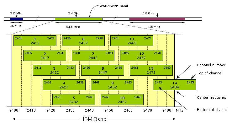
The frequency range from around 3 kHz to 300 GHz is commonly called radio frequency (RF). This range includes microwave category, which contains the two main frequency ranges that are used for wireless LAN communication: 2,4 and 5 GHz.
Because a range of frequencies might be used for the same purpose, it is customary to refer to the range as a band of frequencies. One of the two main frequency ranges used for wireless LAN communication lies between 2.400 and 2.4835 GHz. The other range lies between 5.150 and 5.825 GHz. The 5-GHz band actually contains the following 4 separate and distinct sub-bands:
- 5.150 to 5.250 GHz
- 5.250 to 5.350 GHz
- 5.470 to 5.725 GHz
- 5.725 to 5.825 GHz
A frequency band contains a continuous range of frequencies. To keep everything orderly and compatible, bands/sub-bands are usually divided into a number of distinct channels. Each channel is known by a channel number and is assigned to a specific frequency.


In the 5-GHz band, each channel is allocated a frequency range that does not overlap the frequencies allocated for any other channel. In other words, the 5-GHz band consists of nonoverlapping channels.
The same is not true for the 2.4-GHz band. Each of its channels is much too wide to avoid overlapping the next lower or upper channel number. In fact, each channel covers the frequency range that is allocated to more than four consecutive channels. The only way to avoid any overlap between adjacent channels is to configure APs to use only channels 1, 6, and 11 (USA) or 2, 7 and 12 (EU, etc). Incluso se puede usar 3, 8 y 13, pero no el 14 ya que está fuera del rango.
Standards

Wireless client devices and APs can be compatible with one or more amendments; however, a client and an AP can communicate only if they both support and agree to use the same amendment.
APs can usually operate on both bands simultaneously to support any clients that might be present on each band. However, wireless clients typically associate with an AP on one band at a time, while scanning for potential APs on both bands. The band used to connect to an AP is chosen according to the OS, wireless adapter driver, and other internal configuration. A wireless client can initiate an association with an AP on one band and then switch to the other band if the signal conditions are better there.
In open space, RF signals propagate or reach further on the 2.4-GHz band than on the 5-GHz band. They also tend to penetrate indoor walls and objects easier at 2.4 GHz than 5 GHz. However, the 2.4-GHz band is commonly more crowded with wireless devices. Remember that only three nonoverlapping channels are available, so the chances of other neighboring APs using the same channels is greater. In contrast, the 5-GHz band has many more channels available to use, making channels less crowded and experiencing less interference.