
Analyzing Cisco Wireless Architectures
The architectures:
- Autonomous AP architecture
- Cloud-based AP architecture
- Split-MAC architectures
Autonomous AP architecture

Autonomous APs offer one or more fully functional, standalone BSSs. They are also a natural extension of a switched network, connecting SSIDs to wired VLANs at the access layer.
From the figure: the SSIDs VLANs must be trunked from the distribution layer switch (where routing commonly takes place) to the access layer, where they are extended further over a trunk link to the AP. Two wireless users that are associated to the same autonomous AP can reach each other through the AP without having to pass up into the wired network.
An autonomous AP must also be configured with a mgmt IP so that you can remotely manage it. The mgmt address is not normally part of any of the data VLANs, so a dedicated mgmt VLAN must be added to the trunk links to reach the AP. Each AP must be configured and mantained individually unless you leverage a mgmt platform such as Cisco Prime Infrastructure or Cisco DNA Center.
Client roaming across autonomous APs is typically limited to the Layer 2 domain, or the extent of a single VLAN. As the wireless network expands, the infrastructure becomes more difficult to configure correctly and becomes less efficient.
Cloud-based AP architecture
In this architecture, the AP management function is pushed out of the enterprise and into the Internet cloud. Cisco Meraki is cloud-based and offers centralized management of wireless, switched, and security networks built from Meraki products. For example, through the cloud networking service, you can configure and manage APs, monitor wireless performance and activity, generate reports, and so on.
Cisco Meraki APs can be deployed automatically, once you register with the Meraki cloud. Each AP will contact the cloud when it powers up and will self-configure. From that point on, you can manage the AP through the Meraki cloud dashboard.
The APs in a cloud-based network are all autonomous. The most visible difference is that all of the APs are managed, controlled, and monitored centrally from the cloud.

From the cloud, you can push out code upgrades and configuration changes to the APs in the enterprise. The Cisco Meraki cloud also adds the intelligence needed to automatically instruct each AP on which channel and transmit power level to use. It can also collect information from all of the APs about things such as RF interference, rogue or unexpected wireless devices that were overheard, and wireless usage statistics.
The data path from the wireless network to the wired network is very short; the autonomous AP links the two networks. Data to and from wireless clients does not have to travel up into the cloud and back; the cloud is used to bring management functions into the data plane. Notice there are 2 paths in the image:
- A control plane: Traffic used to control, configure, manage, and monitor the AP itself
- A data plane: End-user traffic passing through the AP.
Split-MAC architectures
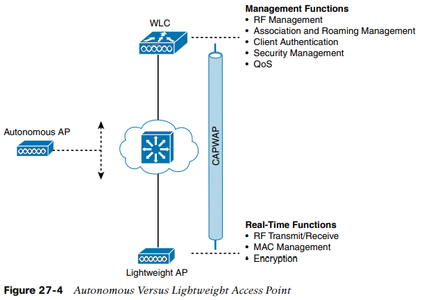
To overcome the limitations of distributed autonomous APs, many of the functions found within autonomous APs have to be shifted toward some central location. In the figure, most of the activities performed by an autonomous AP on the left are broken up into 2 groups: management functions and real-time processes.
- Management functions: not integral to handling frames over the RF channels, but are things that should be centrally administered. Therefore, those functions can be moved to a centrally located platform away from the AP.
- Real-time processes: involve sending/receiving 802.11 frames, beacons, and probe messages. 802.11 data encryption is also handled in real time, on a per-packet basis. The AP must interact with wireless clients on some low level, known as the MAC layer. These functions must stay with the AP hardware, close to the clients.
When the functions of an autonomous AP are divided, the AP hardware is known as a lightweight access point (LAP), and performs only the real-time 802.11 operation. The LAP gets its name because the code image and the local intelligence are stripped down.
The management functions are usually performed on a wireless LAN controller (WLC), which controls many LAPs. The LAP is left with duties in L1 and L2, where frames are moved into and out of the RF domain. The AP becomes totally dependent on the WLC for every other WLAN function, such as authenticating users, managing security policies, and even selecting RF channels and output power.
The lightweight AP-WLC division of labor is known as a split-MAC architecture, where thenormal MAC operations are pulled apart into two distinct locations. This occurs for every AP in the network; each one must boot and bind itself to a WLC to support wireless clients. The WLC becomes the central hub that supports a number of APs scattered about (dispersos por) in the network.
For the LAP to bind to a WLC the two devices must use a tunneling protocol between them, to carry 802.11-related messages and also client data. Remember that the AP and WLC can be located on the same VLAN or IP subnet, but they do not have to be. Instead, they can be located on two entirely different IP subnets in two entirely different locations.
The Control and Provisioning of Wireless Access Points (CAPWAP) tunneling protocol makes this all possible by encapsulating the data between the LAP and WLC within new IP packets. The tunneled data can then be switched or routed across the campus network. The CAPWAP relationship actually consists of two separate tunnels:
- CAPWAP control messages: carries exchanges that are used to configure the AP and manage its operation. The control messages are authenticated and encrypted, so the AP is securely controlled by only the appropriate WLC, then transported over the control tunnel.
- CAPWAP data: used for packets traveling to and from wireless clients that are associated with the AP. Data packets are transported over the data tunnel but are not encrypted by default. When data encryption is enabled for an AP, packets are protected with Datagram TLS (DTLS).

Every AP and WLC must also authenticate each other with digital certificates. An X.509 certificate is preinstalled in each device when it is purchased. By using certificated behind the scenes, every device is properly authenticated before becoming part of the wireless network. This process helps assure that no one can add an unauthorized AP to your network.
The CAPWAP tunneling allows the AP and WLC to be separated geographically and logically. It also breaks the dependence on L2 connectivity between them.

The figure above uses shaded areas to show the extent of VLAN 100. Notice how VLAN 100 exists at the WLC and in the air as SSID 100, near the wireless clients, but not in between the AP and the WLC. Instead, traffic to and from clients associated with SSID 100 is transported across the network infrastructure encapsulated inside the CAPWAP data tunnel. The tunnel exists between the IP address of the WLC and the IP address of the AP, which allows all of the tunneled packets to be routed at L3.
Also, notice how the AP is known by only a single IP. Because the AP sits on the access layer where its CAPWAP tunnels terminate, it can use one IP address for both mgmt and tunneling. No trunk link is needed because all of the VLANs it supports are encapsulated and tunneled as L3 IP packets, rather than individual L2 VLANs. As the wireless network grows, the WLC simply builds more CAPWAP tunnels to reach more APs. Each AP has a control and a data tunnel back to the centralized WLC.
Once CAPWAP tunnels are built from a WLC to one or more LAPs, the WLC begins offering a variety of additional functions:
- Dynamic channel assignment.
- Transmit power optimization.
- Self-healing wireless coverage: If an AP radio dies, the coverage hole can be “healed” by turning up the transmit power of surrounding APs automatically.
- Flexible client roaming.
- Dynamic client load balancing: If two or more APs are positioned to cover the same geographic area, the WLC can associate clients with the least used AP. This distributes the client load across the APs.
- RF monitoring: The WLC manages each AP so that it scans channels to monitor the RF usage. By listening to a channel, the WLC can remotely gather information about RF interference, noise, signals from neighboring APs, and signals from rogue APs or ad hoc clients.
- Security management: The WLC can authenticate clients from a central service and can require wireless clients to obtain an IP address from a trusted DHCP server before allowing them to associate and access the WLAN.
- Wireless IPS (WIPS): Leveraging its central location, the WLC can monitor client data to detect and prevent malicious activity.

The split-MAC concept can be applied to several different network architectures. Each architecture places the WLC in a different location within the network (a choice that also affects how many WLCs might be needed to support the number of APs required).
One approach is to locate the WLC in a central location so that you can maximize the number of APs joined to it (unified or centralized WLC deployment) which tends to follow the concept that most of the resources users need to reach are located in a central location such as a data center or the Internet. Traffic to and from wireless users would travel over CAPWAP tunnels that reach into the center of the network, near the core. A centralized WLC also provides a convenient place to enforce security policies that affect all wireless users. Typical unified WLCs can support a maximum of 6000 APs.
A WLC can also be located in a central position in the network, inside a data center in a private cloud. The WLC exists as a VM rather than a physical device. If the cloud computing platform already exists, then deploying a cloud-based WLC becomes straightforward. Such a controller can typically support up to 3000 APs (if more needed, are more WLC VMs).
For small campuses or distributed branch locations, where the number of APs is relatively small in each, the WLC can be co-located with a stack of switches. This is known as embedded WLC deployment because the controller is embedded within the switching hardware. Typical Cisco embedded WLCs can support up to 200 APs.
Finally, in small-scale environments, such as small, midsize, or multisite branch locations, you might not want to invest in dedicated WLCs at all. In this case, the WLC function can be co-located with an AP that is installed at the branch site. This is known as Cisco Mobility Express WLC deployment. The AP that hosts the WLC forms a CAPWAP tunnel with the WLC, along with any other APs at the same location. A Mobility Express WLC can support up to 100 APs.

Summary:

Cisco AP modes
Many Cisco APs can operate in either autonomous or lightweight, depending on which code image is loaded and run.
From the WLC, you can also configure a LAP to operate in one of the following special-purpose modes:
- Local: default LAP mode. When not transmitting, scans other channels for noise levels, measure interference, IDS...
- Monitor: the AP doesn't transmit at all, but its receiver is enabled to act as a dedicated sensor (IDS, detect rogue APs, determine position of stations through location-based services).
- FlexConnect: An AP at a remote site can locally switch traffic between an SSID and a VLAN if its CAPWAP tunnel to the WLC is down and if it is configured to do so.
- Sniffer
- Rogue detector: correlates MACs heard on the wired networks with those heard over the air. Rogues are those appearing in both.
- Bridge: An AP becomes a dedicated bridge (point-to-point or point-to-multipoint) between two networks. Two APs in bridge mode can be used to link two locations separated by a distance. Multiple APs in bridge mode can form an indoor or outdoor mesh network.
- Flex+Bridge: FlexConnect enabled on a mesh AP.
- SE-Connect: The AP dedicates its radios to spectrum analysis on all wireless channels (discover sources of interference).
Remember that a lightweight AP is normally in local mode when it is providing BSSs and allowing client devices to associate to wireless LANs. When an AP is configured to operate in one of the other modes, local mode (and the BSSs) is disabled.