
Building a Wireless LAN (teoría sobre WLCs + LAPs; split-MAC)
Introduction
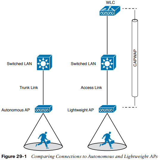
The AP maps each VLAN to a WLAN and BSS.
- The autonomous AP has a single wired Ethernet interface, which means that multiple VLANs must be brought to it over a trunk link.
- A LAP also has a single wired Ethernet interface; however, it must be paired with a WLC to be fully functional. Wired VLANs that terminate at the WLC can be mapped to WLANs that emerge at the AP. Even though multiple VLANs are being extended from the WLC to the AP, they are all carried over the CAPWAP tunnel between the two. That means the AP needs only an access link to connect to the network infrastructure and terminate its end of the tunnel.
To configure and manage Cisco APs, you can connect a serial console cable from your PC to the console port on the AP. Once the AP is operational and has an IP address, you can also Telnet/SSH to connect to its CLI over the wired network. Autonomous APs support browser-based management sessions via HTTP/HTTPS. You can manage LAPs from a browser session to the WLC.
Accessing a Cisco WLC
To connect and configure a WLC, you will need to open a web browser to the WLC’s management address with either HTTP or HTTPS. This can be done only after the WLC has an initial configuration and a management IP address assigned to its management interface. The web-based GUI provides an effective way to monitor, configure, and troubleshoot a wireless network. You can also connect to a WLC with an SSH session, where you can use its CLI to monitor, configure, and debug activity.
Both the web-based GUI and the CLI require management users to log in. Users can be authenticated against an internal list of local usernames or against an authentication, authorization, and accounting (AAA) server, such as TACACS+ or RADIUS.
Connecting a Cisco WLC
The Cisco WLC has several different types of connections. WLCs are not like routers or switches: the terms ports and interfaces refer to different concepts.
- Controller ports are physical connections made to an external wired or switched network.
- Controller interfaces are logical connections made internally within the controller.
Ports
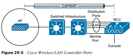
You can connect several different types of controller ports to your network:
- Service port: for out-of-band management, system recovery, initial boot functions; always connect to a switch port in access mode.
- DS port: used for all normal AP and management traffic; usually connects to a switch port in 802.1Q trunk mode.
- Console port: used for out-of-band management, system, recovery, and initial boot functions; asynchronous connection to a terminal emulator (9600 baud, 8N1).
- Redundancy port: used to connect to a peer controller for HA operation.
Controllers can have a single service port that must be connected to a switched network. Usually, the service port is assigned to a management VLAN so that you can access the controller with SSH or a web browser to perform initial configuration or for maintenance. Notice that the service port supports only a single VLAN, so the corresponding switch port must be configured for access mode only.
Controllers also have multiple distribution system (DS) ports that you must connect to the network. These ports carry most of the data coming to and going from the controller. For example, the CAPWAP tunnels (control and data) that extend to each of a controller's APs pass across the DS ports. Client data also passes from WLANs to wired VLANs over the ports. In addition, any mgmt traffic using a web browser, SSH, SNMP, TFTP, and so on, normally reaches the controller in-band through the ports.
You might be thinking that distribution system ports is an odd name for what appear to be regular data ports. Recall that the wired network that connects APs together is called the distribution system (DS). With the split MAC architecture, the
point where APs touch the DS is moved upstream to the WLC instead.
Because the DS ports must carry data that is associated with many different VLANs, VLAN tags and numbers become very important. For that reason, the DS ports always operate in 802.1Q trunking mode. When you connect the ports to a switch, you should also configure the switch ports for unconditional 802.1Q trunk mode.
The DS ports can operate independently, each one transporting multiple VLANs to a unique group of internal controller interfaces. For resiliency, you can configure DS ports in redundant pairs. One port is primarily used; if it fails, a backup port is used instead.
To get the most use out of each distribution system port, you can configure all of them to operate as a single logical group, much like an EtherChannel or port-channel on a switch. Controller distribution system ports can be configured as a link aggregation group (LAG) such that they are bundled together to act as one larger link. With a LAG configuration, traffic can be load-balanced across the individual ports that make up the LAG. In addition, LAG offers resiliency; if one individual port fails, traffic will be redirected to the remaining working ports instead.
Be aware that even though the LAG acts as a traditional EtherChannel, Cisco WLCs do not support any link aggregation negotiation protocol, like LACP or PaGP, at all. Therefore, you must configure the switch ports as an unconditional or always-on EtherChannel.
Interfaces
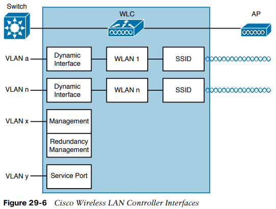
Through its DS ports, a controller can connect to multiple VLANs on the switched network. Internally, the controller must somehow map those wired VLANs to equivalent logical wireless networks. For example, suppose that VLAN 10 is set aside for wireless users in the Engineering division of a company. That VLAN must be connected to a unique WLAN that exists on a controller and its associated APs. The WLAN must then be extended to every client that associates with the SSID "Engineering".
Cisco WLCs provide the necessary connectivity through internal logical interfaces, which must be configured with an IP address, subnet mask, default gateway, and a DHCP server. Each interface is then assigned to a physical port and a VLAN ID. You can think of an interface as a L3 termination on a VLAN. Cisco WLCs support the following interface types:
- Mgmt. interface: used for normal mgmt. traffic, such as RADIUS, user auth., WLC-to-WLC communication, web-based and SSH sessions, SNMP, NTP, syslog, and so on. The mgmt. interface is also used to terminate CAPWAP tunnels between the controller and its APs.
- Redundancy management: the mgmt. IP address of a redundant WLC that is part of an HA pair of controllers. The active WLC uses the mgmt. interface address, while the standby WLC uses the redundancy mgmt. address.
- Virtual interface: IP address facing wireless clients when the controller is relaying client DHCP requests, performing client web authentication, and supporting client mobility.
- Service port interface: bound to the service port and used for out-of-band management.
- Dynamic interface: used to connect a VLAN to a WLAN.
The management interface faces the switched network, where management users and APs are located. Management traffic will usually consist of protocols like HTTPS, SSH, SNMP, NTP, TFTP, and so on. In addition, management interface traffic consists of CAPWAP packets that carry control and data tunnels to and from the APs.
The virtual interface is used only for certain client-facing operations. For example, when a wireless client issues a request to obtain an IP address, the controller can relay the request on to an actual DHCP server that can provide the appropriate IP address. From the client’s perspective, the DHCP server appears to be the controller’s virtual interface address. Clients may see the virtual interface’s address, but that address is never used when the controller communicates with other devices on the switched network. Because the virtual interface is used only for some client management functions, you should configure it with a unique, nonroutable address. For example, you might use 10.1.1.1 because it is within a private address space defined in RFC 1918.
Traditionally, many people have assigned IP address 1.1.1.1 to the virtual interface. Although it is a unique address, it is routable and already in use elsewhere on the Internet. A better practice is to use an IP address from the RFC 1918 private address space that is unused or reserved, such as 192.168.1.1. You could also use a reserved address from RFC 5737 (192.0.2.0/24) that is set aside for documentation purposes and is never used.
The virtual interface address is also used to support client mobility. For that reason, every controller that exists in the same mobility group should be configured with a virtual address that is identical to the others. By using one common virtual address, all the controllers will appear to operate as a cluster as clients roam from controller to controller.
Dynamic interfaces map WLANs to VLANs, making the logical connections between wireless and wired networks. You will configure one dynamic interface for each wireless LAN that is offered by the controller’s APs and then map the interface to the WLAN. Each dynamic interface must also be configured with its own IP address and can act as a DHCP relay for wireless clients. To filter traffic passing through a dynamic interface, you can configure an optional access list.