
Lab 1 - Prepare Both Sites Individually
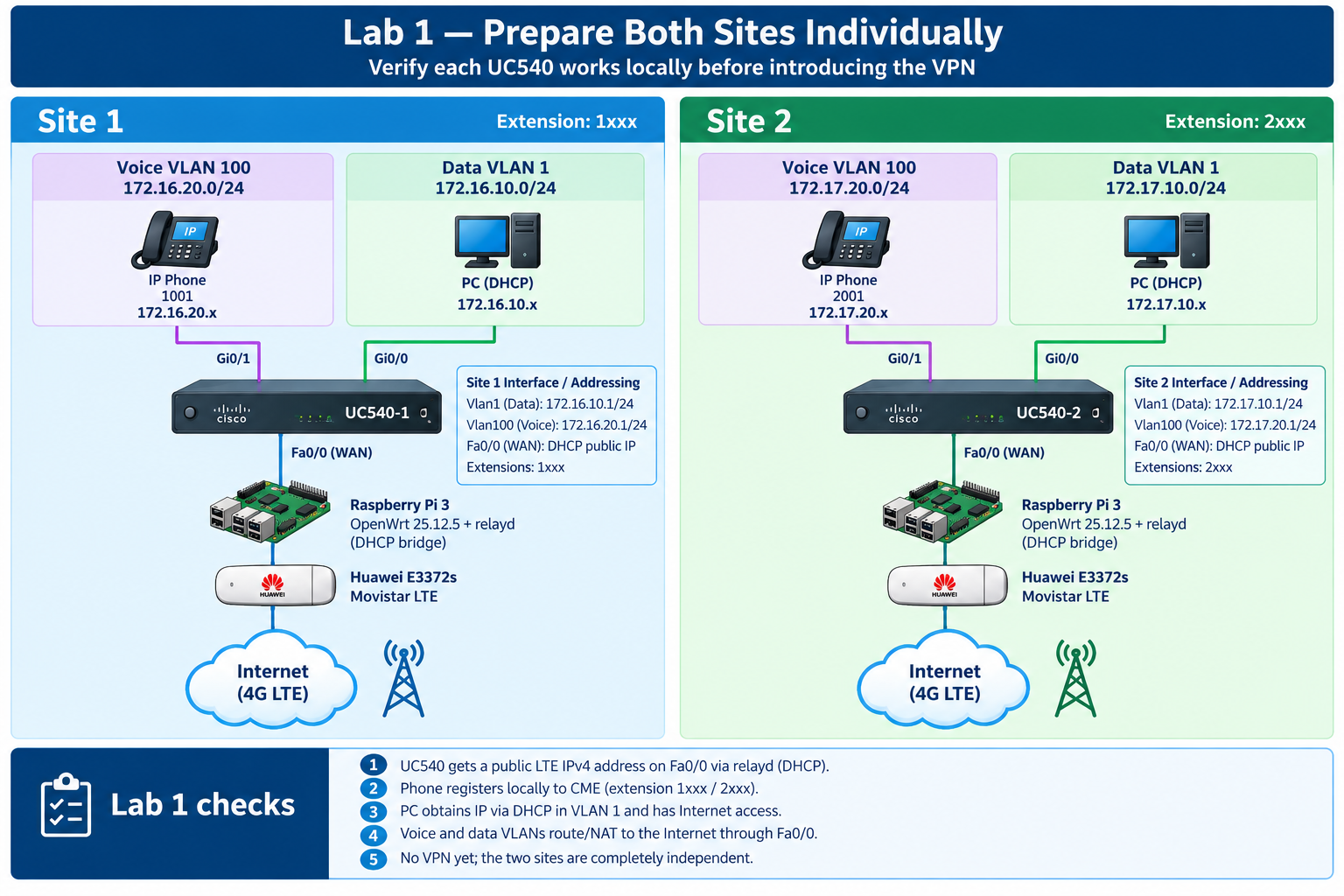
Section 1: Addressing Plan and Telephony Setup Wizard
In this section we are only defining the IP structure for both UC540 sites before touching the configuration. The goal is to keep the lab completely separate my real home networks (10.1.0.0/16 and 10.0.0.0/16) and to preserve the UC540 factory logic: VLAN 1 for data, VLAN 100 for voice, plus the internal CUE /30 link.
| Site 1 | Site 2 | |
|---|---|---|
| Data — VLAN 1 / BVI1 | 172.16.10.0/24 |
172.17.10.0/24 |
| UC540 Data gateway | 172.16.10.1 |
172.17.10.1 |
| Voice — VLAN 100 / BVI100 | 172.16.20.0/24 |
172.17.20.0/24 |
| UC540 Voice/CME IP | 172.16.20.1 |
172.17.20.1 |
| Extensions | 1xxx |
2xxx |
| CUE internal /30 | 172.16.30.0/30 |
172.17.30.0/30 |
| CUE module | 172.16.30.1 |
172.17.30.1 |
| UC540 Loopback0 | 172.16.30.2 |
172.17.30.2 |
| Fa0/0 WAN | DHCP public IPv4 | DHCP public IPv4 |
|
|
|
|
|
|
|
|
|
|
|
|
|
|
|
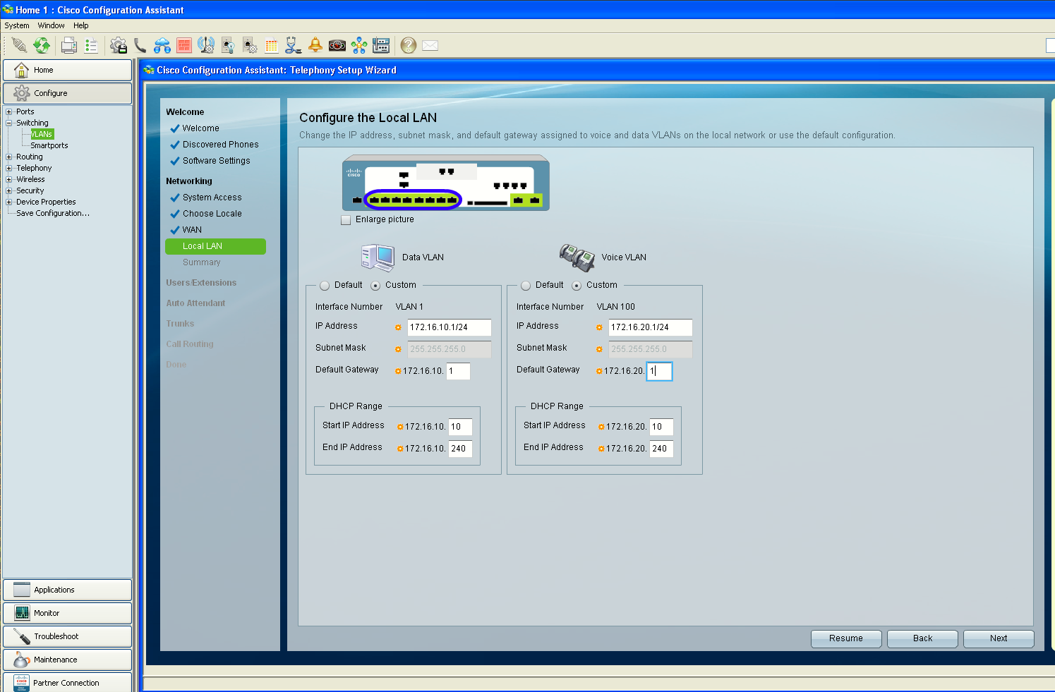
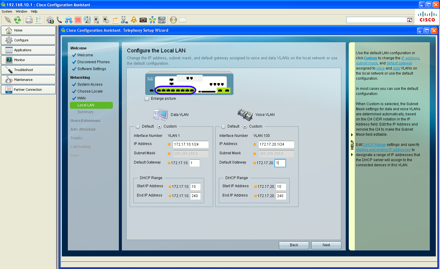
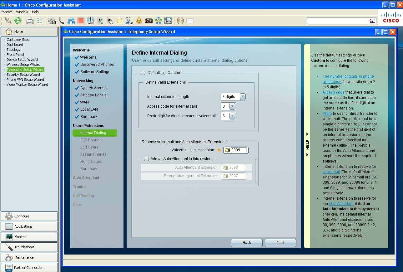
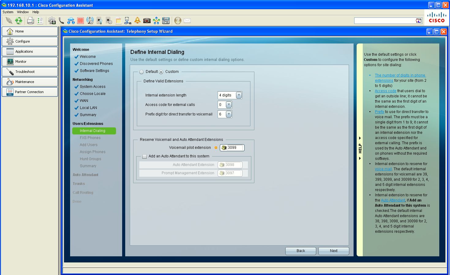
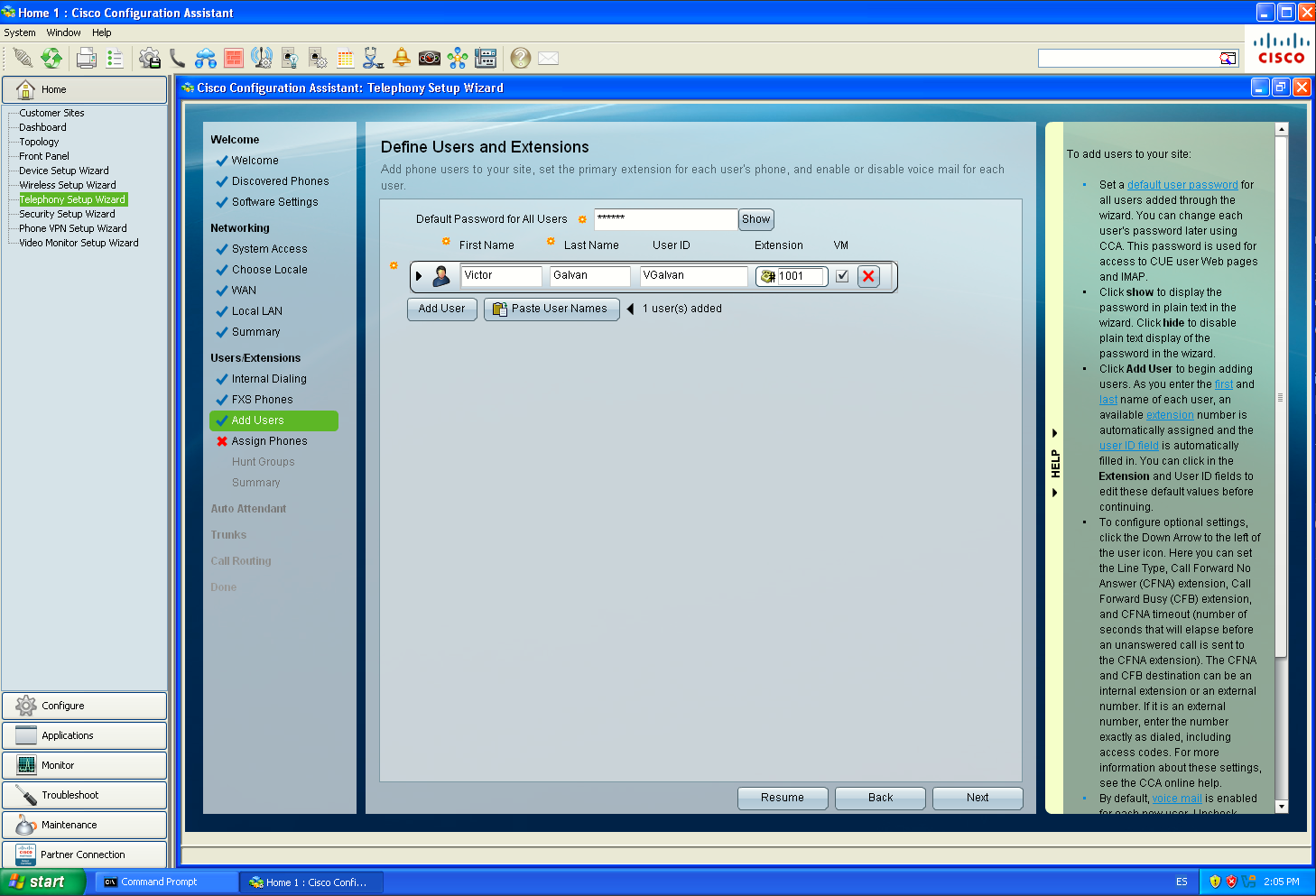
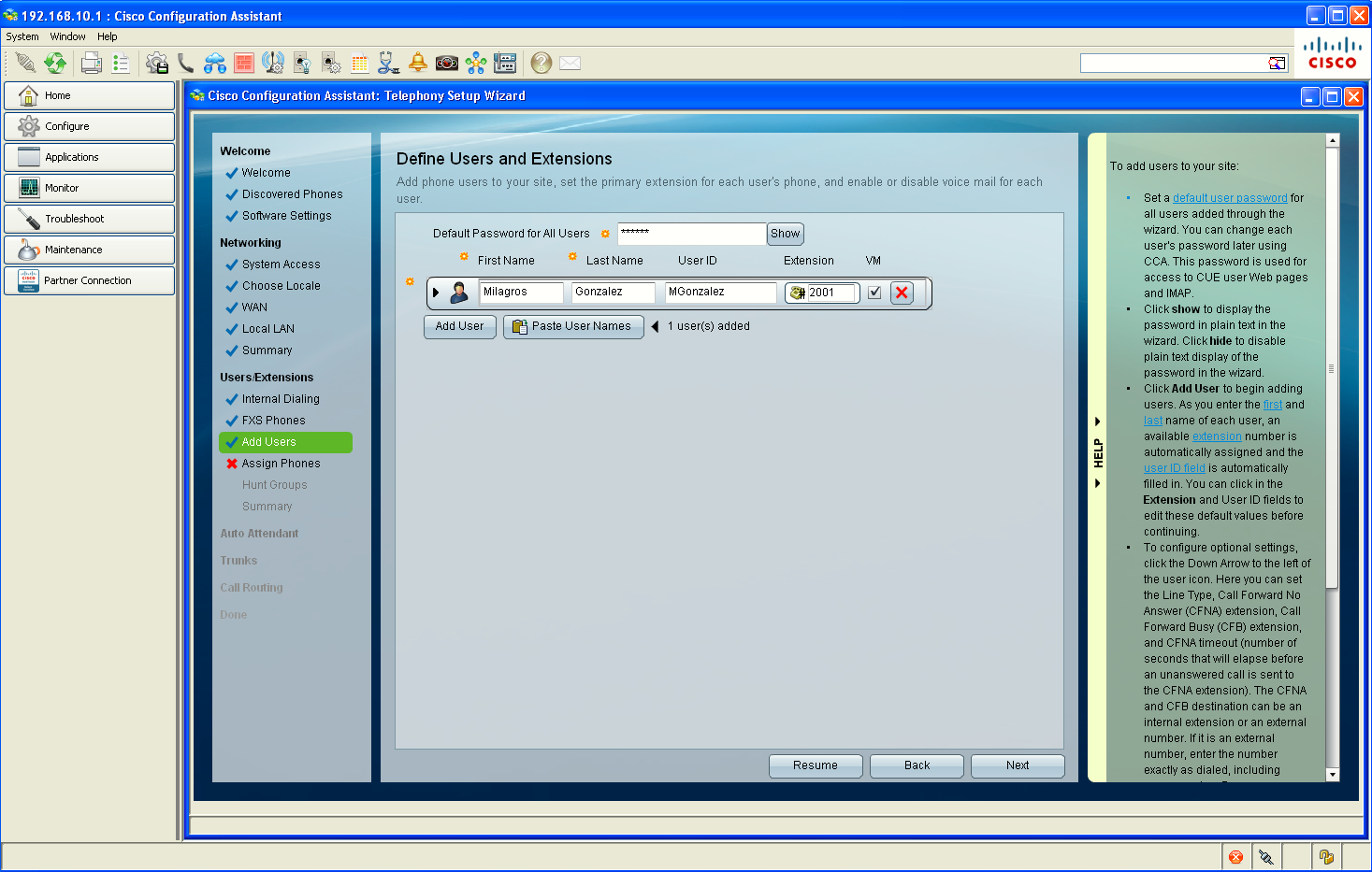
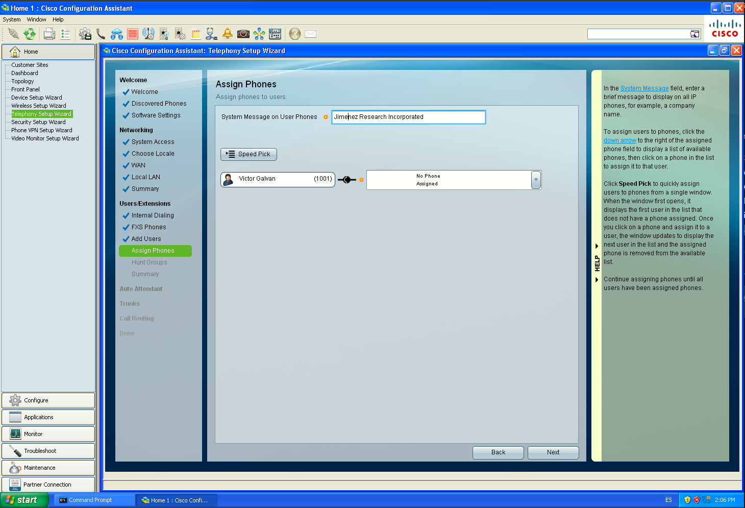
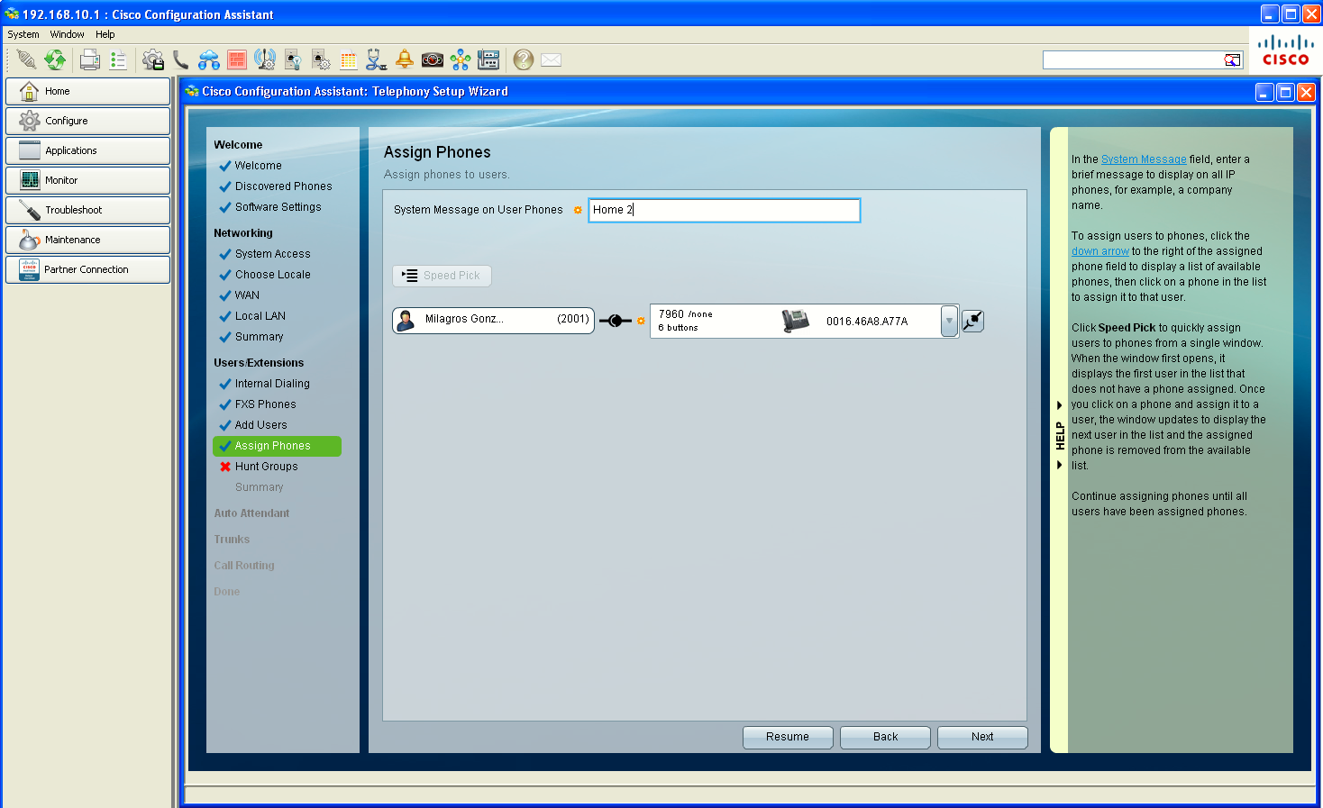
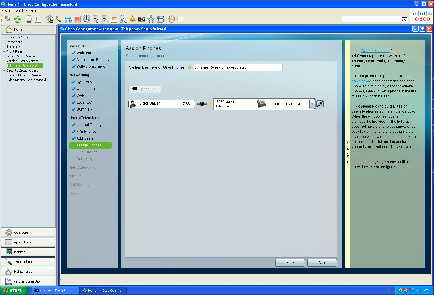
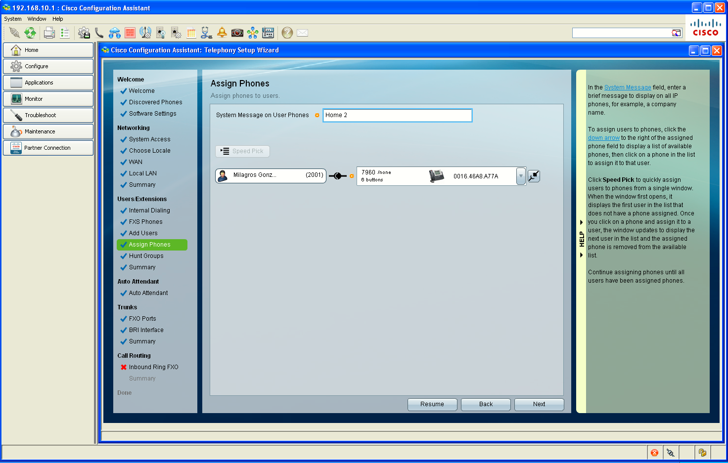
As seen on the images I went through the Telephony Setup Wizard on CCA, to prepare both sites with an streamlined configuration.
Cisco’s own CCA guidance treats the Telephony Setup Wizard as the initial provisioning tool for LAN/WAN, users, extensions, trunks, inbound routing, etc., and recommends saving the configuration after the wizard completes.
Section 2 - Post-Wizard Verification
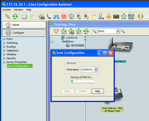
Save the CCA-generated configuration
First thing we'll want to do after Telephony Setup completes is to save the configuration on both sites. Cisco’s UC500 procedure specifically has this as the action after completing the setup wizard. The Telephony Setup Wizard has generated a fairly large amount of configuration:
Data VLAN
Voice VLAN
DHCP pools
CME settings
Users/extensions
Phone configuration
Voice-port configuration
Dial plan
Inbound routing
etc.
Before we start verifying or modifying anything else, we want that known-good CCA-generated configuration stored in startup-config.
We are not changing anything here. The Telephony Setup Wizard already created the addressing; this step is only to confirm that CCA applied the addressing plan correctly.
Verify Data and Voice VLANs in CCA
We are not changing anything here. The Telephony Setup Wizard already created the addressing; this step is only to confirm that CCA applied the addressing plan correctly. Later, the site-to-site VPN and CME dial-peer work will depend on these prefixes being consistent.
|
|
|
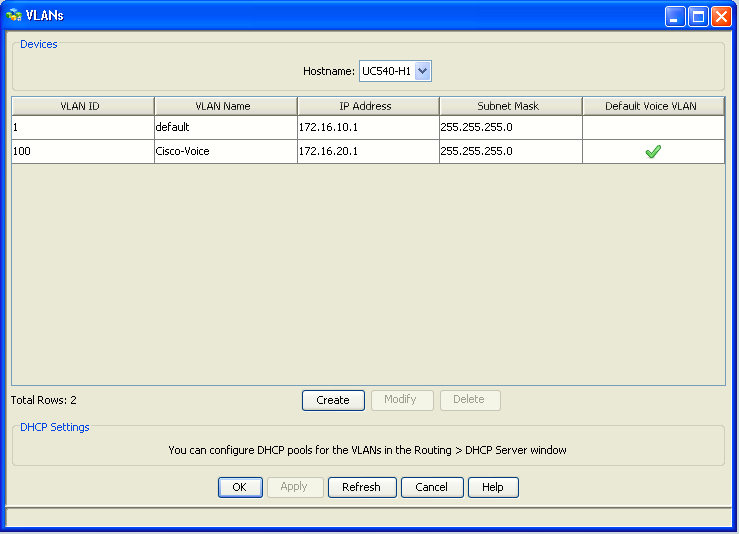
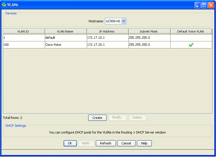
One UC500-specific detail: under the hood, the UC540 normally uses BVI1 and BVI100 as the Layer-3 interfaces rather than placing the IP directly on Vlan1 and Vlan100 while the actual VLAN interfaces may have no IP address. That is normal for the UC500's IRB design.
IRB means Integrated Routing and Bridging.
The idea is:
- the UC540 has several Layer-2 things that need to live in the same broadcast domain:
- switch ports
- VLAN 1 / VLAN 100
- Wi-Fi radio subinterfaces
- IOS bridges those Layer-2 interfaces together
- then a BVI provides the Layer-3 gateway for that whole bridged domain
A BVI is a Bridge-Group Virtual Interface.
So in the UC540, instead of doing the more modern thing:
interface Vlan1
 ip address 172.16.10.1 255.255.255.0

interface Vlan100
 ip address 172.16.20.1 255.255.255.0
Cisco UC500 does this:
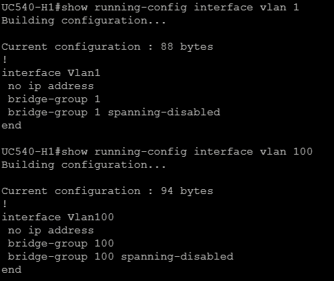
and then puts the gateway IPs on:
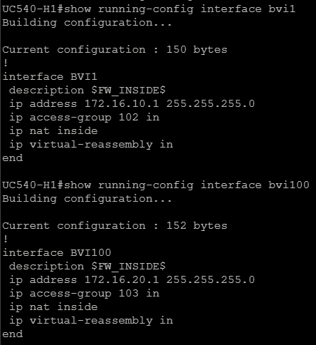
That is exactly how the factory config is built: Vlan1 joins bridge-group 1, Vlan100 joins bridge-group 100, and the IP addresses live on BVI1 and BVI100.
And the UC540 explicitly enables IRB with global config command:
bridge irbThink of it like this:
PCs / switch ports / Wi-Fi
          |
        VLAN 1
          |
     bridge-group 1
          |
        BVI1
     172.16.10.1
          |
       Routing
And for voice:
IP Phones / Wi-Fi voice
          |
       VLAN 100
          |
    bridge-group 100
          |
       BVI100
     172.16.20.1
          |
       Routing
So BVI1 is effectively the default gateway for Data VLAN 1, and BVI100 is the default gateway for Voice VLAN 100.
The reason Cisco used this design is that the UC500 combines router, switch, Wi-Fi, voice hardware and bridge domains in one box. IRB lets IOS bridge all those Layer-2 pieces together while still giving that bridge domain a routable Layer-3 IP. For this lab, the practical rule is simple:
VLAN 1   → Layer 2 container
BVI1     → Layer 3 gateway for Data

VLAN 100 → Layer 2 container
BVI100   → Layer 3 gateway for Voice
So when CCA changes the Data or Voice network, it is really the BVI addresses that matter from the routing point of view.
Verify SmartPort roles on Both Sites
Now that the Data and Voice VLANs are correct, we verify how the physical LAN ports use them. CCA can show a graphical view of the UC540 switch ports. Cisco uses Smartports to apply the correct switchport configuration according to what will be connected to each port.
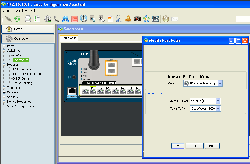
SmartPort configuration: UC540 access ports intended for Cisco IP phones use the IP Phone + Desktop SmartPort role. VLAN 1 carries untagged data traffic and VLAN 100 carries tagged voice traffic. This permits a Cisco phone and a PC connected through the phone to use separate Data and Voice networks over the same switch port.
Verify DHCP scopes in CCA + DNS configuration
Now we confirm that the Telephony Setup Wizard created the correct DHCP pools for both the Data and Voice networks. Depending on the CCA version/layout, it may appear under a slightly different submenu, but we are looking for the UC540 DHCP pools. We should see one scope for the Data network and one for the Voice network.
|
|
|
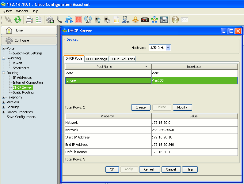
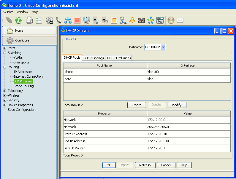
For the Voice DHCP pool, also verify that CCA has configured Option 150 pointing to the CME/TFTP address. Cisco IP phones use DHCP not only to get an IP address, but also to learn where the TFTP server is. In this lab, CME/TFTP lives on the UC540 itself.

The option 150 does not appear on CCA. Can only be checked via CLI.
It is very important that on this step we add a proper DNS setting under the data scope options. Otherwise, PCs connected on this network won't be able to resolve name.
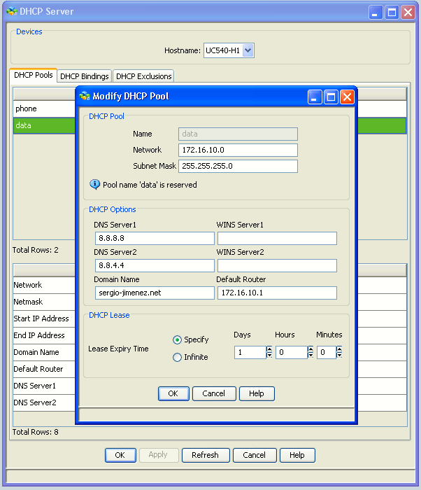
Verify CME system settings and source address
Now we verify that CME is actually using the Voice network address we planned.
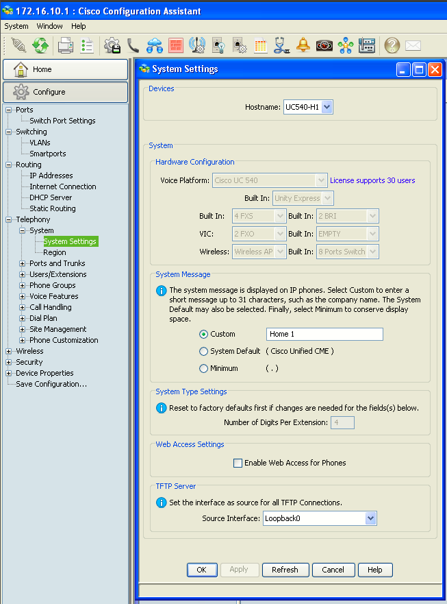
That is the CCA page Cisco provides for the UC500 voice system settings. For now, just confirm the page loads normally and that the UC540 voice system is shown as configured. Do not change anything yet. The more important parameter we want to verify is the CME source address. CCA does not expose every IOS telephony-service parameter clearly, so for this one verification we will use CLI.
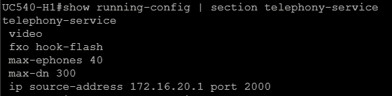
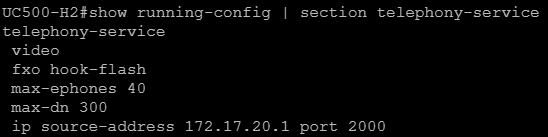
For SCCP phones, this command tells CME:
"Use 172.16.20.1 as the address through which phones communicate with me." (Home 1)
Cisco documents ip source-address specifically as the address/port used by IP phones to communicate with CME
So our design should line up like this (Home 1):
Voice BVI100       172.16.20.1
DHCP gateway       172.16.20.1
DHCP Option 150    172.16.20.1
CME source address 172.16.20.1
SCCP port          2000
Everything points to the same UC540 voice-side address.
Because the UC540 configuration can also contain voice register global (SIP phone support), run:


Cisco CME uses source-address under voice register global for SIP phone registration.
Verify users, phones and extensions in CCA
Now we check that the Telephony Setup Wizard actually created the user/phone assignments we expect.
|
|
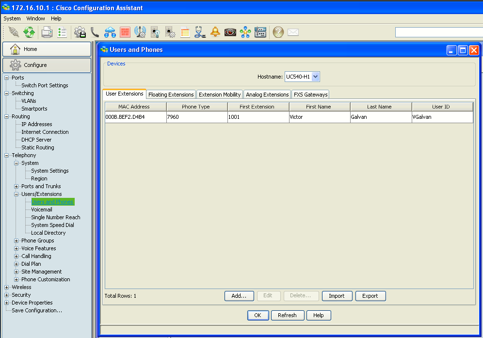
Cisco documents this exact path and notes that registered phones appear here once they are on the correct voice VLAN and can reach DHCP.
Since Site 1 uses the 1xxx extension range, check that the configured phones/users have numbers in that range. Select one phone and click: Edit. Check the main items:
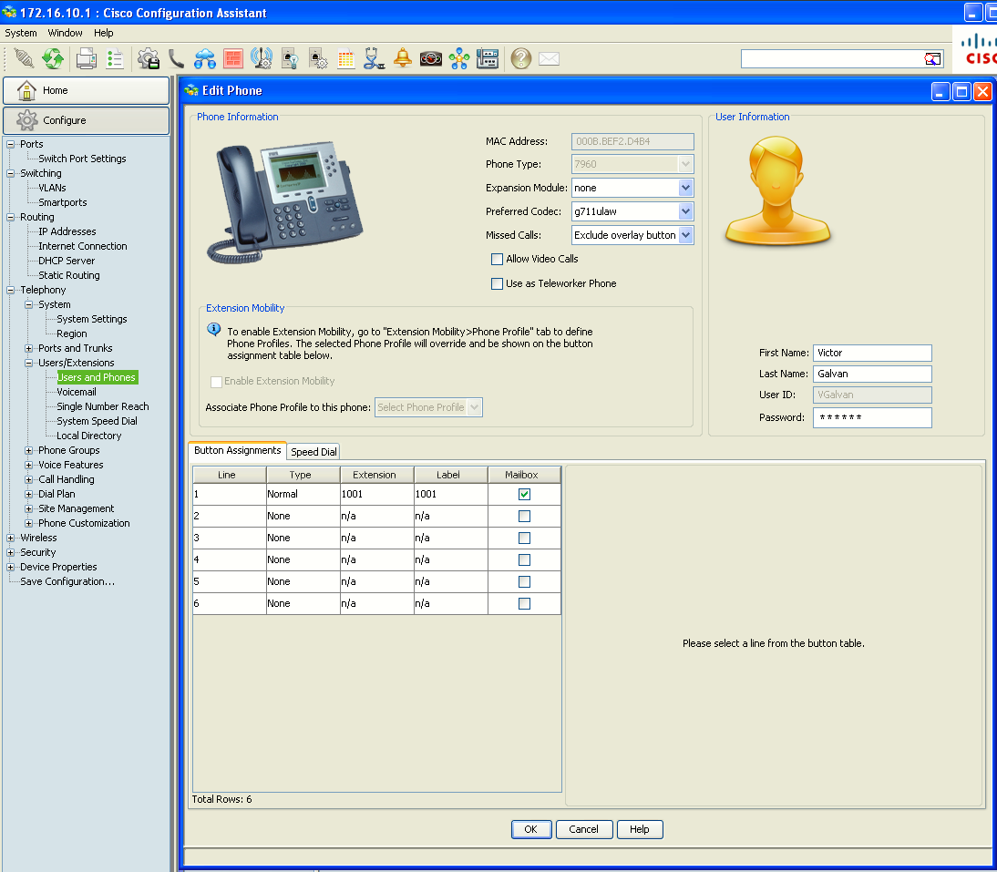
CCA associates extensions with the actual phone configuration here; this is where the line buttons and user information are tied to the phone. CCA links three separate elements here:
Physical phone / MAC
        ↓
Directory number
        ↓
User
For example:
Cisco 7962
MAC xxxx.xxxx.xxxx
        ↓
Extension 1001
        ↓
Site 1 user
At this stage we are only verifying the configuration. Actual phone registration will be tested later.
Verify CUE / Voicemail integration
CME handles call control and extensions, while CUE handles voicemail. They are integrated, but they are separate components inside the UC540. CCA hides most of that complexity and lets us manage voicemail from the same interface.
On Site 1, open:
Configure → Telephony → Users and Extensions → Voicemail
|
|
|
|
|
|
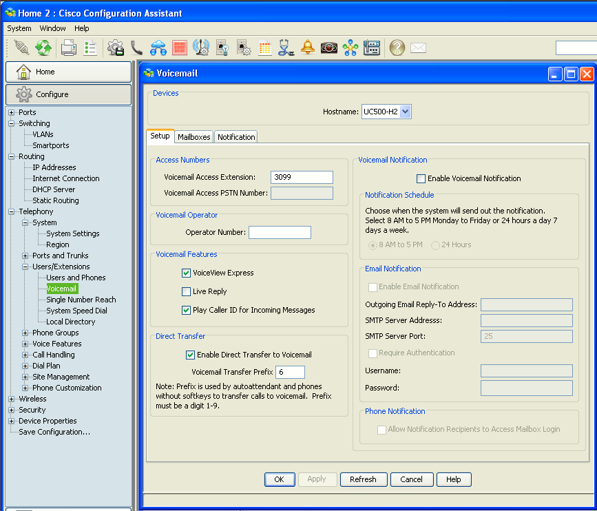
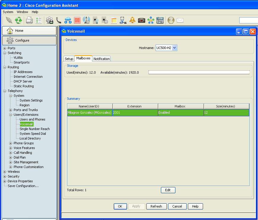
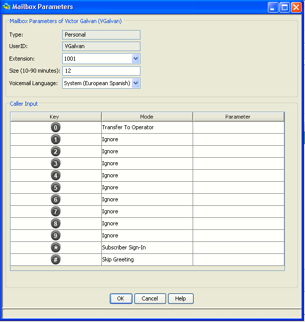
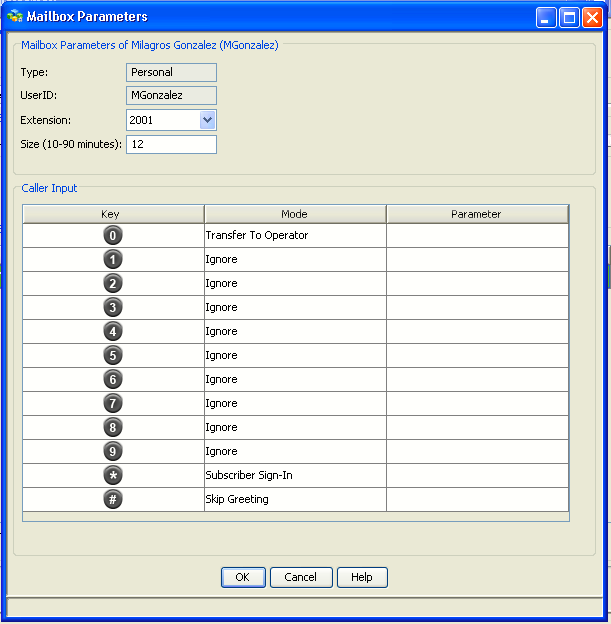
Verify that voicemail is enabled for the extensions created by the Telephony Setup Wizard. For example, extension 1001 should have an associated CUE mailbox.
Also check the voicemail access number. On UC500 systems this is commonly 399, although we should keep the value generated by your wizard. This is the number users dial, or the Messages button uses, to reach CUE.
You may also see Direct Transfer to Voicemail, commonly using a prefix such as 6. Leave the wizard-generated value as it is for now.
Because we recently rebuilt CUE, verify its status from CLI:
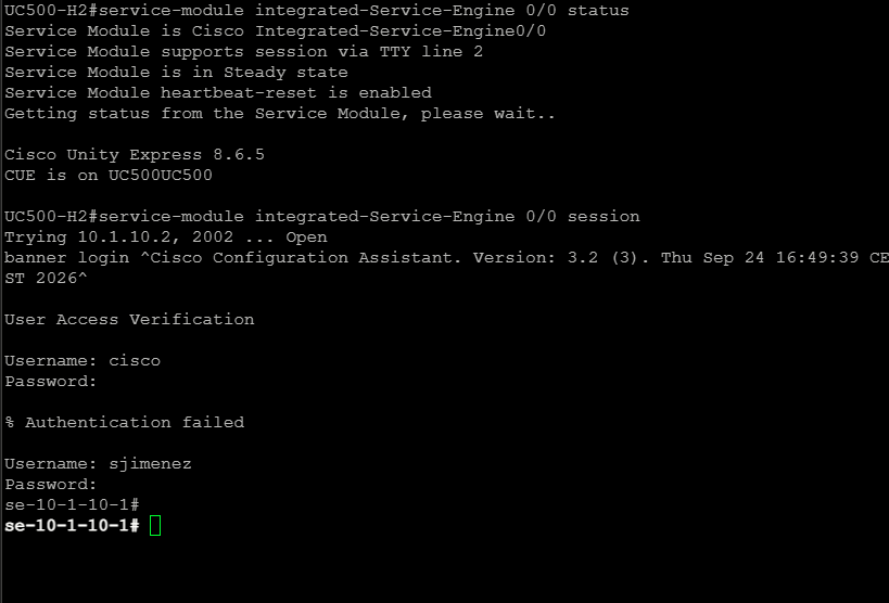
CME and Phone Registration via CLI
Verify registration from CLI:


We cannot test local phone-to-phone calling yet because you only have one phone at each site. That test will happen later across the VPN.
LTE WAN / relayd / Internet Verification
In CCA go to:
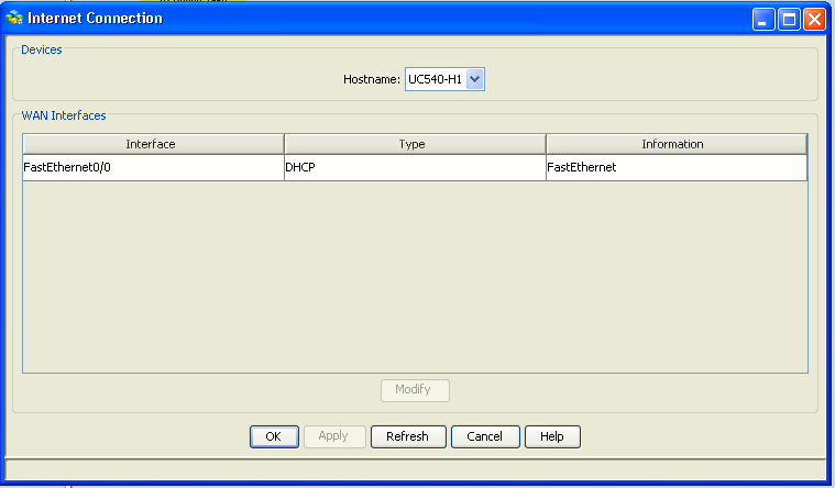
Configure → Routing → Internet Connection
Select FastEthernet0/0. It should show DHCP as the connection type. That is correct for our design, because the UC540 is obtaining the LTE-side address through the OpenWrt relayd bridge rather than doing PPPoE or LTE itself. Cisco CCA exposes this page specifically for UC500 WAN/DHCP configuration.
Do not change Fa0/0 if it already has the configuration we established:
|
|
|
|
|
|
|
|
|
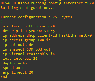
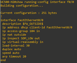
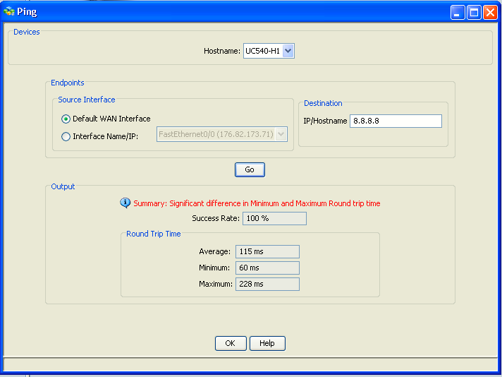
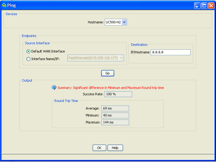
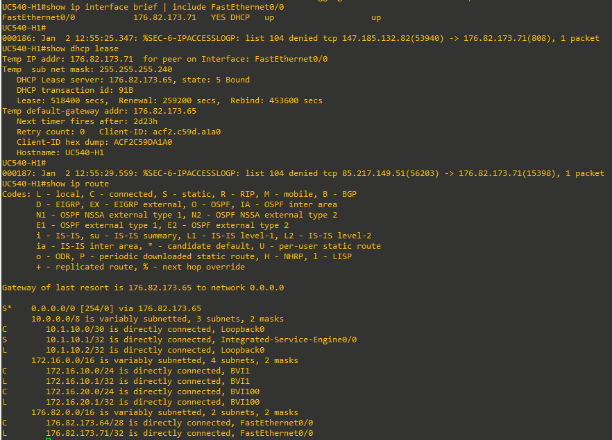
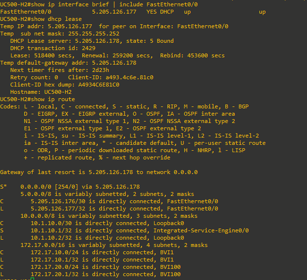
What matters is:
FastEthernet0/0is up/up- it has received the Movistar LTE IPv4 address through the Pi
- there is a default route learned through DHCP
- the UC540 can reach the Internet
The Pi is not acting as the normal routed gateway for the UC540; its job is to bridge/pass the LTE-side connectivity so the UC540 can treat Fa0/0 as its real WAN interface.