
Lab 4.1.2 - Implement MST
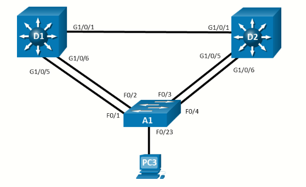
Topology
Objectives
Part 1: Build the Network and Configure Basic Device Settings and Interface Addressing
Part 2: Implement and Observe MST
Part 3: Configure, Tune and Verify Basic MST Operation
Background / Scenario
Cisco’s Per VLAN Spanning Tree (PVST+) provides a significant step up from standard spanning tree in terms of flexibility. PVST+ allows each VLAN to have its own independent spanning tree, thereby making better use of available links in the network. A drawback to PVST+ is that there is an instance of PVST+ running for each VLAN in the network, regardless of whether there are different spanning-tree topologies required. This presents the potential for overwhelming the switch CPU and memory. Additionally, Cisco switches support a finite number of PVST instances. If more VLANs are created than there are PVST+ instances supported on a particular switch, some of the VLANs will not have any STP running, and therefore not have any switching loop protection. PVST+ and Rapid PVST+ are simply unusable in that kind of environment. Lastly, PVST+ and Rapid PVST+ are Cisco-proprietary protocols and generally unusable in mixed vendor environments.
Cisco was involved in the early development of Multiple Spanning Tree. MST was standardized as IEEE 802.1s in 2002 and merged into 802.1Q in 2005. MST is an open protocol derived from RSTP, sharing all its rapid convergence properties, and in fact, the only standardized spanning-tree protocol for VLAN-based networks supported by multiple vendors. MST is a compromise between common spanning-tree and per-VLAN spanning tree. An MST instance represents a unique spanning-tree topology. Multiple MST instances can be created to account for each of the required spanning-tree topologies in a network, and an arbitrary number of VLANs can be mapped to a single MST instance.
In this lab, you will set up two instances of MST, one for VLANs 2 and 3 and the other for VLANs 4 and 5. All other VLANs will be mapped to the default MST instance (also referred to as IST or Internal Spanning Tree).
Note: This lab is an exercise in deploying and verifying MST and does not reflect networking best practices
Note: The switches used with CCNP hands-on labs are Cisco 3650 with Cisco IOS XE release 16.9.4 (universalk9 image) and Cisco 2960+ with IOS release 15.2 (lanbase image). Other routers and Cisco IOS versions can be used. Depending on the model and Cisco IOS version, the commands available and the output produced might vary from what is shown in the labs.
Note: Ensure that the switches have been erased and have no startup configurations. If you are unsure contact your instructor.
Required Resources - Sergio Jiménez's Version
- 2 Switches (Cisco 3560)
- 1 Switch (Cisco 2960CX)
- 1 PC
- Console cables to configure the Cisco IOS devices via the console ports
- Ethernet cables as shown in the topology
Instructions
Part 1: Build the Network and Configure Basic Device Settings and Interface Addressing
In Part 1, you will set up the network topology and configure basic settings.
Step 1: Cable the network as shown in the topology
Attach the devices as shown in the topology diagram, and cable as necessary.
Step 2: Configure basic settings for each switch.
- Console into each switch, enter global configuration mode, and apply the basic settings. The startup configurations for each device are provided below.
Switch D1 (Cisco 3560)
Switch D2 (Cisco 3560)hostname D1 banner motd # D1, Multiple Spanning Tree # spanning-tree mode rapid-pvst line con 0 exec-timeout 0 0 logging synchronous exit interface range f0/1,f0/5-6 switchport trunk encapsulation dot1q switchport mode trunk no shutdown exit vlan 2 name SecondVLAN exit vlan 3 name ThirdVLAN exit vlan 4 name FourthVLAN exit vlan 5 name FifthVLAN exit
Switch A1 (Cisco 2960CX)hostname D2 banner motd # D2, Multiple Spanning Tree # spanning-tree mode rapid-pvst line con 0 exec-timeout 0 0 logging synchronous exit interface range f0/1,f0/5-6 switchport trunk encapsulation dot1q switchport mode trunk no shutdown exit vlan 2 name SecondVLAN exit vlan 3 name ThirdVLAN exit vlan 4 name FourthVLAN exit vlan 5 name FifthVLAN exit
Note: Outputs and Spanning Tree topologies highlighted in this lab may be different than what you observe using your own equipment. It is critically important for you to understand how Spanning Tree makes its decisions, and how those decisions impact the operational topology of the networkhostname A1 banner motd # A1, Multiple Spanning Tree # spanning-tree mode rapid-pvst line con 0 exec-timeout 0 0 logging synchronous exit interface range g0/1-4 switchport mode trunk no shutdown interface g0/8 no shutdown exit vlan 2 name SecondVLAN exit vlan 3 name ThirdVLAN exit vlan 4 name FourthVLAN exit vlan 5 name FifthVLAN exit
Part 2: Implement and Observe MST
Step 1: Configure MST on D1 and D2
In this step we will configure MST on D1 and D2 only. We will do this so we can observe their interaction with each other as well as their interaction with A1.
- On D1 and D2, issue the command spanning-tree mode mst
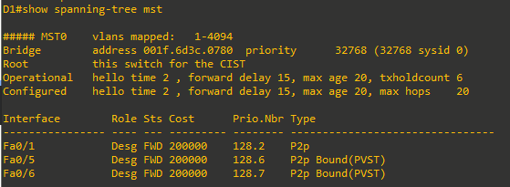
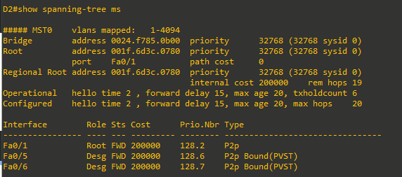
D1(config)#spanning-tree mode mst D2(config)#spanning-tree mode mst - At this point, with no MST-specific configuration, MST Instance 0 is operational for all VLANs. Issue the command show spanning-tree and you will see in the output that the spanning tree information is about MST 0. Issue the command show spanning-tree mst and you will see the MST-specific STP information that is specific to MST 0 only. Take note of the information displayed for interfaces f0/5 and f0/6 because they are connected to a switch that is not running MST. Their type is listed as P2p Bound (PVST).
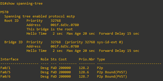
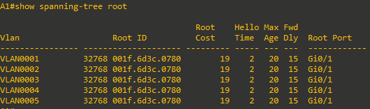
- The basic behavior of MST is the same as spanning tree, where a root bridge must be selected, then root ports, and finally best paths to the root bridge from all non-root bridges. In the current network, we can see that D1 has been elected the root bridge. The bridge priority defaults to 32768, so the election is based on D1 having a lower base MAC address. Issue the command show spanning-tree root on switch A1. Switch A1 is running five instances of spanning tree.

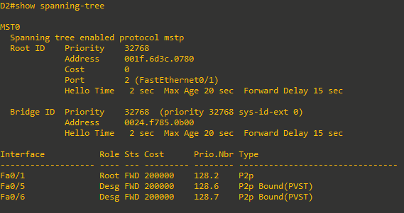
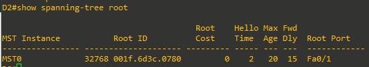
- Issue the show spanning-tree root command on D2 and the output will be different. This is because with MST, only one instance of the spanning-tree algorithm runs, regardless of the number of VLANs mapped to it.
- Configure A1 to use MST.
A1(config)#spanning-tree mode mst


Part 3: Configure, Tune, and Verify Basic MST Operation
In the last part, you configured all three switches to run MST. In this part, you will further configure, tune, and verify MST to support the unique topological requirements.
Step 1: Create and verify an MST configuration
MST allows network engineers to reduce the load of the spanning-tree protocol while still providing unique spanning-tree topologies for groups of VLANs. MST configuration must be completed by hand on each switch individually.
Complete the following tasks on switch D1:
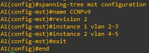
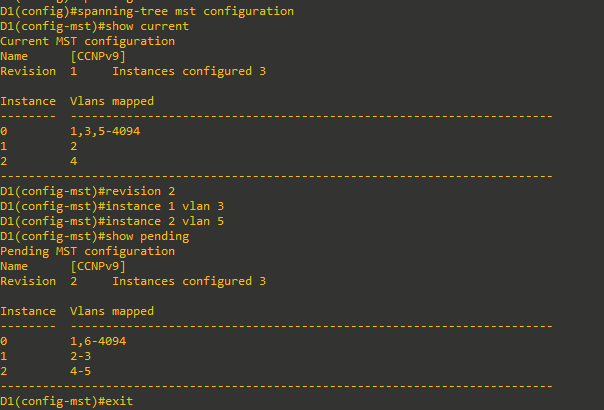
- Enter MST configuration mode using the command spanning-tree mst configuration. Configure an MST region name. Our example will be CCNPv9. Configure an MST configuration revision number. Our example will be 1. Configure instance 1 to include VLAN 2. Configure instance 2 to include VLAN 4. Commit the configuration by typing exit and returning to global configuration mode.

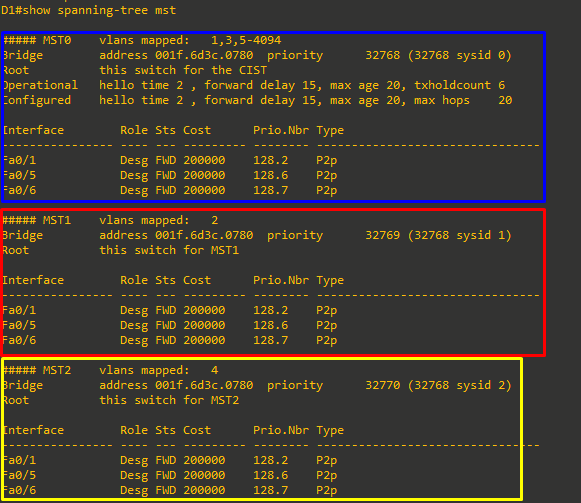
- Issue the command show spanning-tree mst to verify the configuration is in place
Note: While in spanning-tree mst configuration mode, you can use the show current and show pending
commands to view current and pending configuration settings.

- This configuration does not propagate to other switches. Each switch exchanges digest information summarizing the VLAN to-Instance mappings it has configured. If a switch receives a BPDU with a different digest, it assumes that the sender is in a different MST region. The output below is what A1 shows in the topology used to create this lab. Notice that the ports connected to D1 are classified as P2p Bound (RSTP).
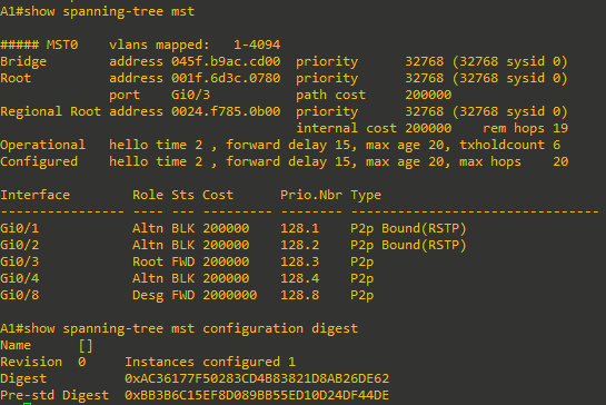
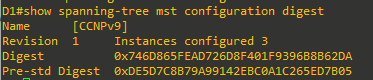
And here is the digest from D1:

As you can see here, the digest values are different. - Configure MST on D1, change the revision number to 2 and add VLAN 3 to instance 1 and VLAN 5 to instance 2.

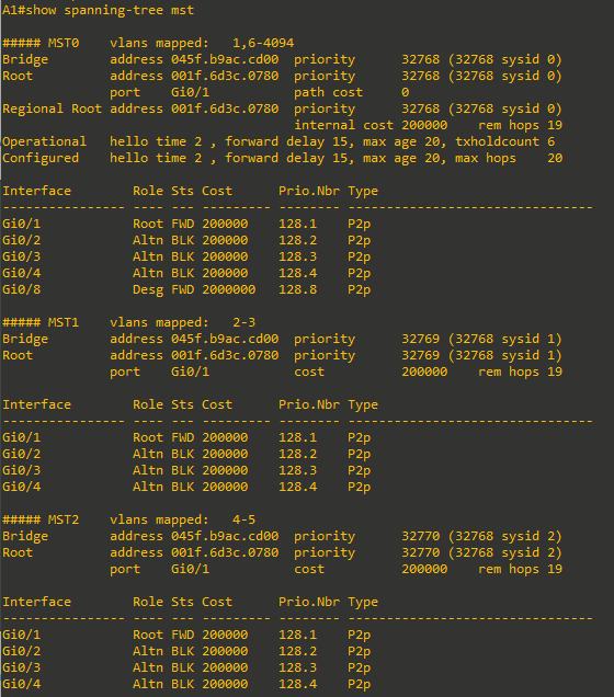
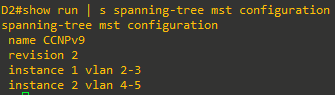
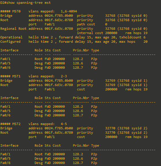
- Now configure D2 and A1 with the same configuration settings (name CCNPv9, revision2, instance 1 vlans 2-3, instance 2 vlans 4-5). After completing the configuration on D2 and A1, the output of show spanning-tree mst on A1 should be similar to the following output. D1 in this case is the root for all 3 instances.


Step 2: Controlling the Root Bridge
Just like with PVST+ and Rapid PVST+, the current root bridge was elected based on the lowest Bridge ID (consisting of the Priority, extended system ID equal to the VLAN ID, and base MAC address values).
With the priority and extended system IDs being identical, the root bridge's MAC is numerically smaller than the local bridge’s MAC. The result is that in a completely un-configured network, one single switch will be elected as the root bridge. The resulting choice of switch may or may not be desirable.
With PVST+ or Rapid PVST+, root bridge selection is done for each VLAN. With MST, the root bridge is based on instances.
There are two basic ways to manipulate the configuration to control the location of the root bridge:
- The spanning-tree mst instance-id priority value command can be used to manually set a priority value
- The spanning-tree mst instance-id root { primary | secondary } command can be used to automatically set a priority value.
The difference between the two is the priority command will set a specific number (multiple of 4096) as the priority, while the root primary command will set the local bridge's priority to 24,576 (if the local bridge MAC is lower than the current root bridge's MAC) or 4096 lower than the current root's priority (if the local bridge MAC is higher than the current root bridge's MAC).
The logic behind this operation is straight-forward. The root primary command tries to lower the priority only as much as is needed to win the root election, while leaving priorities between 24576 and the default 32768 for use by secondary bridges. The command always takes the entire Bridge ID into account when computing the resulting priority value.
The spanning-tree mst instance-id secondary command will statically set the local bridge’s priority to 28,672. In an otherwise unconfigured network where all switch priorities default to 32,768, the root primary command will set the priority on the switch to 24,576 (two increments lower than the default priority) while the root secondary command will set the priority on the secondary root to the 28,672 (one increment lower than the default priority).
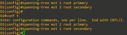
- Modify D1 and D2 so that D1 is elected the primary root bridge for MST Instance 1 and D2 is elected the primary root bridge for MST Instance 2. D1 should be elected as the secondary root bridge for MST Instance 2, and D2 should be elected as the secondary root bridge for MST Instance 1. You will need to make configuration changes on both D1 and D2.
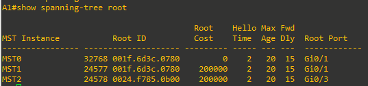
- After you have configured both D1 and D2, go to A1 and issue the command show spanning-tree root. In this output, you will see the root bridges differentiated.

From the above output, you can see that the root port for VLAN 1 is G0/1 and the root port for VLAN 2 is G0/3. A1 is the root bridge for MST Instance 0 in this example

Step 3: Adjust port cost values to impact root and designated port selection.
As the network is implemented right now, there are two direct paths between switch A1 and the root bridge for each MST. Path and port costs are evaluated to determine the shortest path to the root bridge. In the case where there are multiple equal cost paths to the root bridge, additional attributes must be evaluated. In our case, the lower interface number (for example, G0/1) is chosen as the Root Port, and the higher interface number (for example, G0/2) is put into a spanning tree Blocking state.
You can see which ports are blocked with the show spanning-tree vlan-id command or the show spanning-tree blockedports command. For now, examine VLAN 1 on A1.
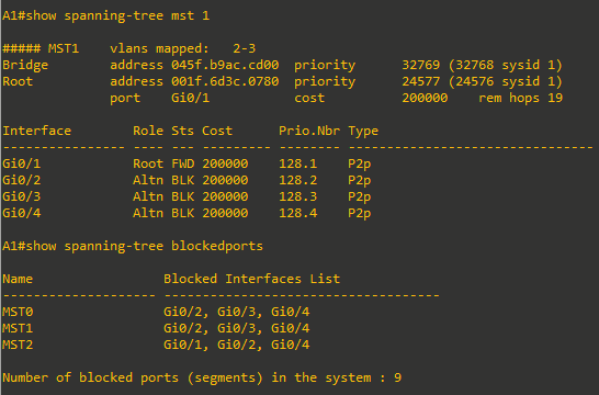
- On A1, issue the commands show spanning-tree mst 1 and show spanning-tree blockedports

As you can see, MST 1 has its Root Port on G0/1 and G0/2, G0/3, and G0/4 are Alternate Blocking Ports. To manipulate which port becomes the Root Port on non-root bridges, change the port cost (a value between 1 and 200,000,000) or port priority value (a value between 0 and 240 in increments of 16). Remember that this change could have an impact on downstream switches as well.
Note: The changes you are about to implement are considered topology changes and could have a significant impact on the overall structure of the spanning tree in your switch network. Do not make these changes in a production network without careful planning and prior coordination. - On A1, shutdown interfaces G0/1 and G0/2, assign a new port cost of 1000 to G0/2 using the spanning-tree mst 1 cost value command, and then issue the no shutdown command on the ports.
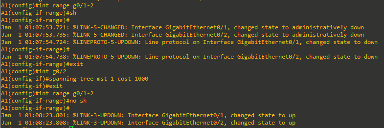
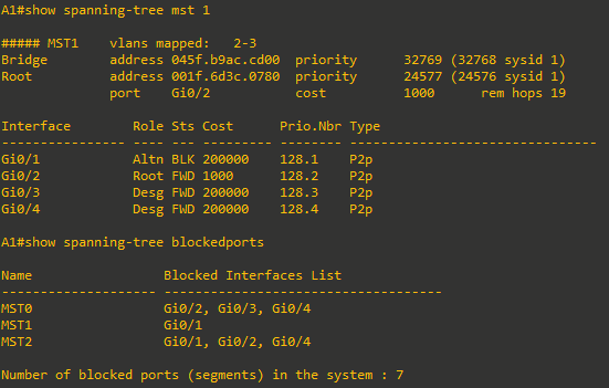
- Now verify that this impacts root port selection on A1 using the show spanning-tree mst 1 and show spanning-tree blockedports commands.

From the output, you can see that the root port selected by A1 for VLAN 1 is now interface G0/2, and the port (and root) cost is now 1000.

Step 4: Adjust port priority values to impact root port selection.
The next method to impact root port selection is configured on the root bridge itself. In our current network topology, A1 has two connections to the root bridge for MST Instance 2, switch D2. The root port has been selected, in this case based on the lowest port ID. Port ID is made up of two values, labeled as Prio (Priority) and Nbr (Number).
Note: The port number is not necessarily equal to the interface ID. A switch may use any port number for STP purposes as long as they are unique for each port on the switch.
The port priority can be any value between 0 and 240, in increments of 16 (older switches may allow setting the priority in different increments).
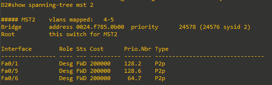
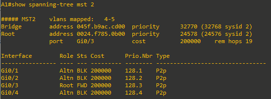
- On A1, issue the command show spanning-tree mst 2 and take note of the port ID values listed.

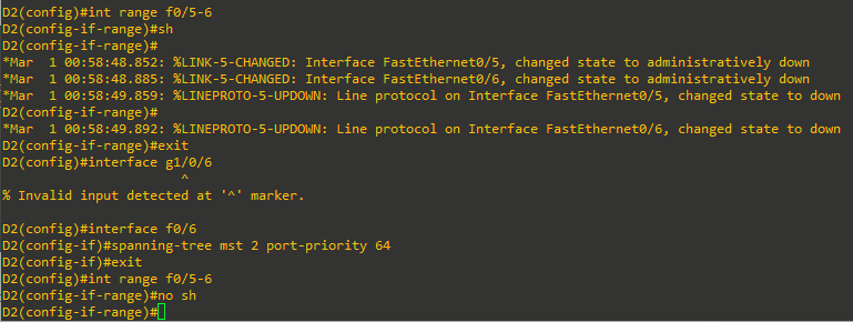
As expected with two equal-cost paths to the root bridge, the lower port ID was selected as the root port. - Modify the port priority of D2 interface F0/6 so that it becomes the preferred port by issuing the spanning-tree mst 2 port-priority value interface configuration command. Use a value of 64.

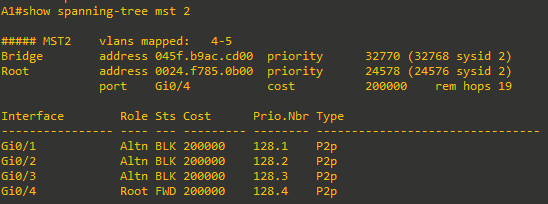
- On A1, issue the show spanning-tree mst 2 command and you will see that Fa0/4 is now the selected root port. This selection is based on the lower priority value of D2 interface G1/0/6. Notice that the lower priority value does not appear in any A1 output.


Device Configs - Final
Switch D1 (3560)
D1#show run
Building configuration...

Current configuration : 1289 bytes
!
! Last configuration change at 00:45:15 UTC Mon Mar 1 1993
!
version 15.0
no service pad
service timestamps debug datetime msec
service timestamps log datetime msec
no service password-encryption
!
hostname D1
!
boot-start-marker
boot-end-marker
!
!
!
no aaa new-model
system mtu routing 1500
!
!
!
!
!
!
!
!
!
!
!
!
spanning-tree mode mst
spanning-tree extend system-id
!
spanning-tree mst configuration
 name CCNPv9
 revision 2
 instance 1 vlan 2-3
 instance 2 vlan 4-5
!
spanning-tree mst 1 priority 24576
spanning-tree mst 2 priority 28672
!
vlan internal allocation policy ascending
!
!
!
!
!
!
!
!
!
!
!
!
!
!
!
interface FastEthernet0/1
 switchport trunk encapsulation dot1q
 switchport mode trunk
!
interface FastEthernet0/2
!
interface FastEthernet0/3
!
interface FastEthernet0/4
!
interface FastEthernet0/5
 switchport trunk encapsulation dot1q
 switchport mode trunk
!
interface FastEthernet0/6
 switchport trunk encapsulation dot1q
 switchport mode trunk
!
interface FastEthernet0/7
!
interface FastEthernet0/8
!
interface GigabitEthernet0/1
!
interface Vlan1
 no ip address
!
ip http server
ip http secure-server
!
!
!
!
!
vstack
banner motd ^C D1, Multiple Spanning Tree ^C
!
line con 0
 exec-timeout 0 0
 logging synchronous
line vty 0 4
 login
line vty 5 15
 login
!
end
Switch D2 (3560)
D2#sh run
Building configuration...

Current configuration : 1337 bytes
!
! Last configuration change at 01:00:56 UTC Mon Mar 1 1993
!
version 15.0
no service pad
service timestamps debug datetime msec
service timestamps log datetime msec
no service password-encryption
!
hostname D2
!
boot-start-marker
boot-end-marker
!
!
!
no aaa new-model
system mtu routing 1500
!
!
!
!
!
!
!
!
!
!
!
!
spanning-tree mode mst
spanning-tree extend system-id
!
spanning-tree mst configuration
 name CCNPv9
 revision 2
 instance 1 vlan 2-3
 instance 2 vlan 4-5
!
spanning-tree mst 1 priority 28672
spanning-tree mst 2 priority 24576
!
vlan internal allocation policy ascending
!
!
!
!
!
!
!
!
!
!
!
!
!
!
!
interface FastEthernet0/1
 switchport trunk encapsulation dot1q
 switchport mode trunk
!
interface FastEthernet0/2
!
interface FastEthernet0/3
!
interface FastEthernet0/4
!
interface FastEthernet0/5
 switchport trunk encapsulation dot1q
 switchport mode trunk
!
interface FastEthernet0/6
 switchport trunk encapsulation dot1q
 switchport mode trunk
 spanning-tree mst 2 port-priority 64
!
interface FastEthernet0/7
!
interface FastEthernet0/8
!
interface GigabitEthernet0/1
!
interface Vlan1
 no ip address
 shutdown
!
ip http server
ip http secure-server
!
!
!
!
!
vstack
banner motd ^C D2, Multiple Spanning Tree ^C
!
line con 0
 exec-timeout 0 0
 logging synchronous
line vty 0 4
 login
line vty 5 15
 login
!
end
Switch A1 (2960CX)
A1#sh run
Building configuration...

Current configuration : 1341 bytes
!
! Last configuration change at 01:09:13 UTC Sat Jan 1 2000
!
version 15.2
no service pad
service timestamps debug datetime msec
service timestamps log datetime msec
no service password-encryption
!
hostname A1
!
boot-start-marker
boot-end-marker
!
!
no aaa new-model
system mtu routing 1500
!
!
!
!
!
!
!
!
!
!
!
!
!
!
!
spanning-tree mode mst
spanning-tree extend system-id
!
spanning-tree mst configuration
 name CCNPv9
 revision 2
 instance 1 vlan 2-3
 instance 2 vlan 4-5
!
!
!
!
!
vlan internal allocation policy ascending
!
!
!
!
!
!
!
!
!
!
!
interface GigabitEthernet0/1
 switchport mode trunk
!
interface GigabitEthernet0/2
 switchport mode trunk
 spanning-tree mst 1 cost 1000
!
interface GigabitEthernet0/3
 switchport mode trunk
!
interface GigabitEthernet0/4
 switchport mode trunk
!
interface GigabitEthernet0/5
!
interface GigabitEthernet0/6
!
interface GigabitEthernet0/7
!
interface GigabitEthernet0/8
!
interface GigabitEthernet0/9
!
interface GigabitEthernet0/10
!
interface GigabitEthernet0/11
!
interface GigabitEthernet0/12
!
interface Vlan1
 no ip address
!
ip forward-protocol nd
!
ip http server
ip http secure-server
!
!
!
!
banner motd ^C A1, Multiple Spanning Tree ^C
!
line con 0
 exec-timeout 0 0
 logging synchronous
line vty 0 4
 login
 transport input ssh
line vty 5 15
 login
 transport input ssh
!
!
end

A1#