
Lab - Implement EIGRP for IPv6
Topology
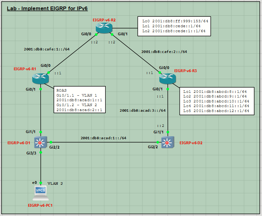
Addressing Table
| Device | Interface | IPv6 Address/Prefix Length | Link Local Address |
| EIGRP-v6-R1 | G0/0 | 2001:db8:cafe:1::1/64 | fe80::1:1 |
| G0/1.1 | 2001:db8:acad:1::1/64 | fe80::1:2 | |
| G0/1.2 | 2001:db8:acad:2::1/64 | fe80::1:3 | |
| EIGRP-v6-R2 | G0/0 | 2001:db8:cafe:1::2/64 | fe80::2:1 |
| G0/1 | 2001:db8:cafe:2::2/64 | fe80::2:2 | |
| Loopback 0 | 2001:db8:ff:999:153/64 | fe80::2:3 | |
| Loopback 1 | 2001:db8:cede::1/64 | fe80::2:4 | |
| Loopback 2 | 2001:db8:cede:1::1/64 | fe80::2:5 | |
| EIGRP-v6-R3 | G0/0 | 2001:db8:cafe:2::1/64 | fe80::3:1 |
| G0/1 | 2001:db8:acad:3::1/64 | fe80::3:2 | |
| Loopback 1 | 2001:db8:abcd:8::1/64 | fe80::3:3 | |
| Loopback 2 | 2001:db8:abcd:9::1/64 | fe80::3:4 | |
| Loopback 3 | 2001:db8:abcd:10::1/64 | fe80::3:5 | |
| Loopback 4 | 2001:db8:abcd:11::1/64 | fe80::3:6 | |
| Loopback 5 | 2001:db8:abcd:12::1/64 | fe80::3:7 | |
| EIGRP-v6-D2 | G2/2 | 2001:db8:acad:1::2/64 | fe80::d2:1 |
| G1/1 | 2001:db8:acad:3::2/64 | fe80::d2:2 | |
| EIGRP-v6-PC1 | NIC | SLAAC | EUI-64 |
Objectives
- Part 1: Build the Network and Configure Basic Device Settings
- Part 2: Implement EIGRP for IPv6 and Named EIGRP
- Part 3: Tune and Optimize EIGRP for IPv6
Background / Scenario
EIGRP for IPv6 has the same overall operation and features as EIGRP for IPv4. However, there are a few major differences between them:
- IPv6 unicast routing must be enabled before the routing process can be configured.
- In the absence of the router having any IPv4 addresses, a 32-bit router ID must be configured for the routing process to start.
- EIGRP for IPv6 is configured directly on the router interfaces.
In this lab, you will configure the network with EIGRP for IPv6. You will also configure passive interfaces, propagate a default route, configure a summary route, implement routing protocol authentication, modify load balancing, and filter routes with a prefix list.
This lab is an exercise in configuring the options available with EIGRP for IPv6. It does not necessarily reflect implementation best practices.
Required Resources - Sergio Jiménez's Version
- 3 Routers (Cisco IOSv)
- 2 Switches (Cisco IOSvL2)
- 1 VPC
Instructions
Part 1: Configure Basic Device Settings
Console into each device, enter global configuration mode, and apply the basic settings. The startup configurations for each device are provided below.
EIGRP-v6-R1
hostname EIGRP-v6-R1
no ip domain lookup
ipv6 unicast-routing
banner motd # EIGRP-v6-R1, Implement EIGRP for IPv6 #
line con 0
exec-timeout 0 0
logging synchronous
exit
line vty 0 4
privilege level 15
exec-timeout 0 0
password cisco123
login
exit
interface g0/0
ipv6 address 2001:db8:cafe:1::1/64
ipv6 address fe80::1:1 link-local
no shutdown
exit
interface g0/1
no ip address
no shutdown
exit
interface g0/1.1
description VLAN 1 Interface
encapsulation dot1q 1
ipv6 address fe80::1:2 link-local
ipv6 address 2001:db8:acad:1::1/64
no shutdown
exit
interface g0/1.2
description VLAN 2 Interface
encapsulation dot1q 2
ipv6 address fe80::1:3 link-local
ipv6 address 2001:db8:acad:2::1/64
no shutdown
exit
end
EIGRP-v6-R2
hostname EIGRP-v6-R2
no ip domain lookup
ipv6 unicast-routing
banner motd # EIGRP-v6-R2, Implement EIGRP for IPv6 #
line con 0
exec-timeout 0 0
logging synchronous
exit
line vty 0 4
privilege level 15
exec-timeout 0 0
password cisco123
login
exit
interface g0/0
ipv6 address fe80::2:1 link-local
ipv6 address 2001:db8:cafe:1::2/64
no shutdown
exit
interface g0/1
ipv6 address fe80::2:2 link-local
ipv6 address 2001:db8:cafe:2::2/64
no shutdown
exit
interface loopback 0
description Internet host
ipv6 address fe80::2:3 link-local
ipv6 address 2001:db8:ff:999::153/64
no shutdown
exit
interface loopback 1
ipv6 address fe80::2:4 link-local
ipv6 address 2001:db8:cede::1/64
no shutdown
exit
interface loopback 2
ipv6 address fe80::2:5 link-local
ipv6 address 2001:db8:cede:1::1/64
no shutdown
exit
end
EIGRP-v6-R3
hostname EIGRP-v6-R3
no ip domain lookup
ipv6 unicast-routing
banner motd # EIGRP-v6-R3, Implement EIGRP for IPv6 #
line con 0
exec-timeout 0 0
logging synchronous
exit
line vty 0 4
privilege level 15
exec-timeout 0 0
password cisco123
login
exit
interface g0/0
ipv6 address fe80::3:1 link-local
ipv6 address 2001:db8:cafe:2::1/64
no shutdown
exit
interface g0/1
ipv6 address fe80::3:2 link-local
ipv6 address 2001:db8:acad:3::1/64
no shutdown
exit
interface loopback 1
ipv6 address fe80::3:3 link-local
ipv6 address 2001:db8:abcd:8::1/64
no shutdown
interface loopback 2
ipv6 address fe80::3:4 link-local
ipv6 address 2001:db8:abcd:9::1/64
no shutdown
interface loopback 3
ipv6 address fe80::3:5 link-local
ipv6 address 2001:db8:abcd:10::1/64
no shutdown
interface loopback 4
ipv6 address fe80::3:6 link-local
ipv6 address 2001:db8:abcd:11::1/64
no shutdown
interface loopback 5
ipv6 address fe80::3:7 link-local
ipv6 address 2001:db8:abcd:12::1/64
no shutdown
end
EIGRP-v6-D1
hostname EIGRP-v6-D1
no ip domain lookup
banner motd # EIGRP-v6-D1, Implement EIGRP for IPv6 #
line con 0
exec-timeout 0 0
logging synchronous
line vty 0 4
privilege level 15
exec-timeout 0 0
password cisco123
login
vlan 2
name HOST-VLAN
interface range g1/1, g2/2
switchport mode trunk
no shutdown
exit
interface g3/3
switchport mode access
switchport access vlan 2
spanning-tree portfast
no shutdown
exit
end
EIGRP-v6-D2
hostname EIGRP-v6-D2
no ip domain lookup
ipv6 unicast-routing
banner motd # EIGRP-v6-D2, Implement EIGRP for IPv6 #
line con 0
exec-timeout 0 0
logging synchronous
exit
line vty 0 4
privilege level 15
exec-timeout 0 0
password cisco123
login
exit
interface g2/2
no switchport
ipv6 address fe80::d1:1 link-local
ipv6 address 2001:db8:acad:1::2/64
no shutdown
exit
interface g1/1
no switchport
ipv6 address fe80::d1:2 link-local
ipv6 address 2001:db8:acad:3::2/64
no shutdown
exit
end
Set the clock on each device if necessary, and update the timezone settings.
conf t
clock timezone CET +1
clock summer-time CEST recurring last Sunday March 02:00 Sunday October 02:00
Save the config.
Verify that PC1 generates an IPv6 address. Verify that PC1 can ping its default gateway at fe80::1:3.
Part 2: Implement EIGRP for IPv6 and Named EIGRP
In this part of the lab, you will configure and verify EIGRP in the network. Routers R1 and R3 will used Named EIGRP, while router R2 will use Classic EIGRP. After you have established the network, you will examine the differences in how each version of EIGRP deals with metrics.
For the lab, you will use the Autonomous System number 43 on all routers.
Step 1: Configure EIGRP for IPv6 on R2
- Start the configuration of Classic EIGRP by issuing the ipv6 router eigrp 43 command.
- Configure the EIGRP Router ID using the eigrp router-id command. Use the number 2.2.2.2 for R2.
- Identify the interfaces that should be configured with EIGRP and the networks that should be included in the EIGRP topology table. This is done on the interfaces with the ipv6 eigrp command.
- Verify the interfaces now involved in EIGRP with the show ipv6 eigrp interfaces command.
Step 2: Configure Named EIGRP for IPv6 on R1 and R3
- Start the configuration of Named EIGRP by issuing the router eigrp [ name ] command. The name parameter can be a number, but the number does not identify an Autonomous System as it does with Classic EIGRP, it simply identifies the process. For our purposes, name the process EIGRP_IPV6.
- Enter into address-family configuration mode with the address-family ipv6 unicast autonomous-system 43 command. It is not necessary to configure EIGRP for IPv6 on the interfaces. In named-mode configuration, EIGRP for IPv6 is automatically enabled on all interfaces that are configured with an IPv6 address.
- Configure the EIGRP Router ID using the eigrp router-id command. Use the number 1.1.1.1.
- Repeat the configuration process on R3 and D2. For the R3 router ID use 3.3.3.3, and for the D2 router ID use 132.132.132.132.
Step 3: Verify EIGRP for IPv6
- A few seconds after configuring the network statements on R1, R3 and D2, you should have seen EIGRP adjacencies being formed, as noted at the console by messages similar to the one below.
- To verify that routing is working, ping from PC1 to Interface Loopback 1 on R3 (2001:db8:abcd:8::1). The
ping should be successful. - On R1, examine the EIGRP entries in the IPv6 routing table using the show ipv6 route eigrp command. As you can see, R1 is aware of all of the networks that have been configured in the topology. The remote networks that were learned from EIGRP and that appear in the routing table were learned from routers R2 and R3 as indicated by the link local address that is displayed for these entries. Note that in some cases, EIGRP for IPv6 has two equal cost routes for a network.
- Verify the IPv6 EIGRP neighbor relationships. Remember D1 should not have any EIGRP neighbor relationship because it is not participating in the EIGRP routing protocol.
- Issue the show ipv6 eigrp interfaces detail command to examine the details of the interfaces that are participating in EIGRP.
- Now examine the EIGRP topology table using the show ipv6 eigrp topology all-links command. The all-links parameter instructs the router to display routes that are not successors or feasible successors. We will focus on the routes to 2001:db8:abcd:10::/64 and 2001:db8:cafe:2::/64. There are several things to notice.
Remember that the topology table is EIGRP’s database of route information. EIGRP selects the best paths, based on the DUAL algorithm, and offers them to the IP routing table. However, the IP routing table does not have to use those offered paths, because the router may have learned about the same network from a more reliable routing source, which would be a routing source with a lower administrative distance.
We will focus on the routes, highlighted in the above output, to 2001:db8:abcd:10::/64 and 2001:db8:cafe:2::/64. There are several things to notice:
- The entry for the 2001:db8:abcd:10::/64 network shows two successors, while the entry for 2001:db8:cafe:2::/64 shows only one successor. Both entries show two paths. The path with the lowest Feasible Distance (FD) is selected as the successor and is offered to the routing table. For 2001:db8:abcd:10::/64, there are two paths with equal FD, so they are both successors and both are offered to the global routing table. In the case of 2001:db8:cafe:2::/64, the FD is listed as 19660800. The path via fe80::2:1 shows that number as the FD (first number in parentheses). The path via fe80::d1:1 shows an FD of 2621440, which is higher than the current FD. So that path, although valid, is a higher cost path and is not offered to the routing table.
- The FD listed in the topology table does not match the metric listed in the routing table. For 2001:db8:abcd:10::/64, the routing table shows the metric value 16000 while the topology table shows the FD as 2048000. This is due to the routing table having a limit of 4 bytes (32 bits) for metric information, while EIGRP on R1 is using EIGRP wide metrics, which are 64 bits. Wide metrics are used by Named EIGRP by default. To work around the 32-bit metric size limitation in the routing table, EIGRP divides the wide-metric value by the EIGRP_RIB_SCALE value, which defaults to 128. The value 2048000 divided by 128 is 16000.
Note: A network with mixed EIGRP implementations (Named and Classic in the same routing domain), will have some loss of route clarity, which could lead to sub-optimal path selection. The recommended implementation is to use Named EIGRP in all cases.
- There are no feasible successors listed in the topology table for 2001:db8:abcd:10::/64 or 2001:db8:cafe:2::/64. The feasibility condition requires that the reported distance (RD) to a destination network be less than the current FD for a next-hop to be considered a feasible successor to the route. In the case of 2001:db8:cafe:2::/64, the RD of the path via fe80::d1:1 is listed as
1966080, which is equal to the current FD, which disqualifies this path as a feasible successor. If the path via fe80::2:1 were to be lost, R1 would have to send queries to find a new way to get to 2001:db8:cafe:2::/64. Feasible successors appear only in the topology table. Only successors appear in the routing table. - To see the RIB Scale and metric version values, as well as other protocol information, issue the show ipv6 protocols | section EIGRP_IPv6 command.
- To examine details about a particular path, issue the show ipv6 eigrp topology [address] command. Among other things in this output, you can see the values used in calculating the metric.
Part 3: Tune and Optimize EIGRP for IPv6
In this part of the lab, you will tune and optimize EIGRP for IPv6 through the use of passive interfaces, default router redistribution, summary routes, authentication, load balancing, and route filtering.
Step 1: Configure specific interfaces as passive.
Passive interfaces are interfaces that only partially participate in the operation of a routing protocol. The network that a passive interface is connected to is advertised, while the routing protocol does not actually transmit routing protocol-specific traffic on that interface. Use passive interfaces when you have a connected network that you want to advertise, but you do not want protocol neighbors to appear on that interface. Interfaces supporting users should always be configured as passive. There are two ways to configure interfaces as passive. The first is specifically by interface. The other is to make all interfaces default to passive default. Normally a device with many LAN interfaces will use the default option, and then use the no form of the command on the specific interfaces that should be sending and receiving EIGRP messages.
- On PC1, run Wireshark and set the display capture filter to eigrp. You should see a hello message roughly every five seconds. If PC 1 is capable of running EIGRP for IPv6, you might be able to form an adjacency and interact in the routing domain. This is not desirable.
- On R1, configure af-interface g0/0/1 to be passive.
- On PC1, restart the Wireshark capture with the eigrp capture filter. You should no longer see EIGRP Hello messages.
Step 1: Configure interfaces from default to passive.
The second option for configuring passive interfaces is to configure them all as passive and then issue the no passive-interface command for certain interfaces. This approach is suitable in a security-focused scenario, or when the device has many LAN interfaces. The commands vary depending on whether you are using Classic or Named EIGRP.
- In Classic EIGRP configuration, issue the passive-interface default command followed by no passive-interface [interface designation] command on the interfaces that should be participating in EIGRP. As an example, configure this on R2, and then make interfaces G0/0/0 and G0/0/1 active. Note that you will lose EIGRP adjacencies until the interfaces are active.
- In Named EIGRP configuration, you apply the passive-interface command to the af-interface default configuration, and then no passive-interface command to the af-interface specific interface. On R3, set the af-interface default as passive and then configure G0/0/0 and S0/1/0 as active. Note that you will lose EIGRP adjacencies until the interfaces are active.
- The output of show ip protocols | include (passive) will give you a list of passive interfaces configured for EIGRP.
Step 3: Propagate a default route.
EIGRP for IPv6 can be configured to propagate a default route to other EIGRP routers in the AS. This lab will explore two methods of propagating a default route, either by redistributing a default static route or by sharing a summary default route.
In this topology, interface Loopback 0 on R2 has been configured to simulate an internet destination. Therefore, we will configure a default route on R2 and then configure EIGRP for IPv6 to redistribute the route.
- Configure a static default route on R2 with an exit interface of Loopback0s IPv6 address.
- Go into EIGRP configuration add the redistribute static command.
- At R1, issue the show ipv6 route eigrp | begin EX :: command. Notice the default route is present as an EIGRP external route with an AD of 170. Further, notice that individual routes for the 2001:db8:cede::/64 and 2001:db8:cede:1::/64 networks, representing R2 interfaces Lo1 and Lo2, are present in the routing table.
- On R2, remove the redistribute static command from EIGRP and remove the static default route.
- On R2, configure the ipv6 summary-address command on the GigabitEthernet0/0/0 and GigabtEthernet0/0/1 interfaces. Specify the eigrp 43 and the route ::/0
- Go to router R1 and use the show ipv6 route eigrp command to see the default route that has been injected into the routing table. Notice in the output that the route now appears as an internal EIGRP route with an AD of 90. Also notice that individual routes for the 2001:db8:cede::/64 and 2001:db8:cede:1::/64 networks, representing R2 interfaces Lo1 and Lo2, are no longer present in the routing table. The ipv6 summary-address ::/0 command replaced all individual routes that R2 was advertising.
Note: If you were to add another summary address on R2, similar to what you will do in the next sub-step,
that summary would be advertised as well.
Step 4: Configure an EIGRP for IPv6 Summary Address.
Router R3 is configured with five loopback interfaces that simulate five IPv6 LANs. Those LAN addresses appear in the other EIGRP routers as five individual routes. In order to limit the impact of these five LANs on routing tables and routing protocol traffic, the routes can be configured with a single route summary address that will enable all five networks to be reached without requiring separate information to be shared for each network.
- To optimize EIGRP for IPv6, on R3 summarize the loopback addresses as a single route and advertise the summary route in R3’s EIGRP updates to R1 and R2. Use the same summarization method that is used for IPv4 by finding the bits that all five addresses have in common. The IPv6 loopback addresses could be summarized as 2001:db8:abcd::/61, but common practice is not to split the summary at the nibble level. Therefore, summary masks will normally be 48, 52, 56, and 60 bits. For our exercise, we will specify a 56 bit mask, even though that summary would indicate more networks than R3 is hosting. After configuring the summary route on the interface, notice that the neighbor adjacency between R3 and R2 and R1 is resynchronized (restarted).
- Examine the routing table of R1 to verify that R1 is receiving only one summary route for the loopback interfaces.
Step 5: Configure EIGRP authentication.
EIGRP for IPv6 supports authentication on an interface basis. In other words, each interface can be configured to require authentication of the connected peer. This ensures that connected devices that try to form an adjacency are authorized to do so. Classic EIGRP supports key-chain based MD5-hashed keys, while Named EIGRP adds support for SHA256-hashed keys. The two are not compatible.
In this step, you will configure both types of authentication to exercise the range of options available.
- On R1, R2, and R3, create a key-chain named EIGRPv6-AUTHEN-KEY with a single key. The key should have the key-string $3cre7!!
- On R2, configure interfaces G0/0/0 and G0/0/1 to use the key chain that you just created with MD5. Note that you will lose EIGRP adjacencies until the neighbor interfaces are configured.
- Configure interfaces GigabitEthernet0/0/0 on R1 and R3 to use the key chain with MD5. EIGRP adjacencies with R2 should be restored.
- Use the show ip eigrp interfaces detail | section Gi0/0/0 command to verify authentication is in place and what type it is.
- On R1, R3 and D2, configure HMAC-SHA-256 based authentication using the same shared secret, $3cre7!!, on R1 interface G0/0/1.1, R3 interface G0/0/1, and D2 interfaces G1/0/1 and G1/0/11. Note that EIGRP adjacency will be lost until both ends of a link are configured.
- Use the show ipv6 eigrp interfaces detail command to verify authentication is in place and what type it is.
Step 6: Manipulate load balancing with variance.
By default, load balancing occurs only over equal-cost paths. EIGRP supports up to four equal cost paths by default but can be configured to support as many as 32 with the maximum-paths command.
EIGRP has the added capability to load balance over unequal-cost paths. Load balancing is controlled by the variance parameter. Its value is a multiplier that is used to determine how to deal with multiple paths to the same destination.
Variance is set to 1 by default, so any paths up to the configured maximum number of paths that have an FD equal to the best current FD are also offered to the routing table. This provides equal cost load balancing.
The variance parameter can also be set to zero, which dictates that no load balancing takes place.
The variance parameter can be adjusted so that paths that have an FD that is less than or equal to variance times current best FD are also considered as successors and installed into the routing table. There is an extremely important differentiation here -- to be a feasible successor, the RD of a path must be less than the current best FD. To be considered for unequal load balancing, the FD of the feasible successor is multiplied by the variance value, and if the product of this calculation is less than the current best FD, the feasible successor is promoted to successor.
There are two caveats; first, only feasible successors are considered and second, with unequal cost load balancing, traffic share is proportional to the best metric in the routing table for the given path.
Note: Keep in mind that your routing table may be different than the one created by the examples in this lab. If your results are different, examine them carefully to determine why so that you can thoroughly understand how EIGRP is operating.
- Before manipulating variance, R3 needs to see individual routes from R2 instead of a summary. Therefore, remove the summary routes on R2 so that it will again advertise more specific EIGRP routes to R3.
- On R3, verify that there are again two equal-cost paths to 2001:db8:acad:2::64. In this example, the IPv6 address must be entered in ALL CAPS.
- To change this and allow for the demonstration of variance, change the interface bandwidth for the R2 interfaces G0/0/0 and G0/0/1 to 800000.
- When you examine the routing table on R3, you see that there is no load balancing occurring. All destinations have a single path.
- However, we know there are multiple paths in the network. The first consideration for manipulating variance is that it only works with feasible successors. Examining the topology table on R3 shows that there is a feasible successor for the 2001:db8:acad:2::/64 network. The route via fe80::2:2 out the G0/0/0 interface has an RD less than the FD for the current successor.
- To use the other route for unequal cost load balancing, we can set the variance parameter to 2. This will mean that any path with an RD less than or equal to 5242880 will qualify as a successor (2 x 2621440 = 5242880).
- The output of the show ipv6 route eigrp command now displays two paths available to the 2001:db8:acad:2::/64 network. Notice that the routes have different metrics, but are listed and used just the same. Also, notice adding variance 2 adds a second path to the 2001:db8:cafe:1::/64 network.
Step 7: Filter EIGRP routes using a prefix list.
In this step, you will configure a filter at R2 to block propagation of the network 2001:db8:cafe:1::/64 to R3.
- On R3, issue the command show ipv6 route 2001:db8:cafe:1::/64 command. The output should list two successors, one via fe80::2:2 and one via fe90::d2:2. We want to filter route via fe80::2:1.
- On R2, create an IPv6 prefix list that matches the 2001:db8:cafe:1::/64 network.
- On R2, apply the prefix list as a distribute list for updates exiting the G0/0/1 interface towards R3.
- On R3, issue the show ipv6 route 2001:db8:cafe:1::/64 command. The output should now list one successor fe80::d1:2.
Verify that R3 no longer has a successor route via fe80::2:2 to the 2001:db8:cafe:1::/64 network.