
Lab - Implement Advanced EIGRP for IPv4 Features
Topology
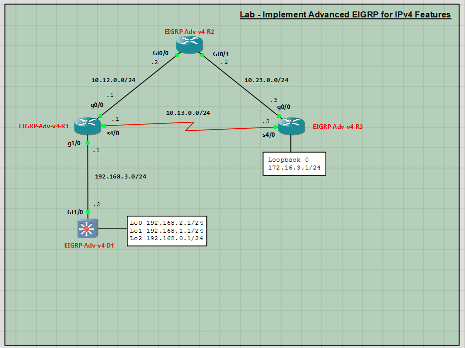
Addressing Table
| Device | Interface | IP Address | Subnet Mask |
| EIGRP-Adv-v4-R1 | G0/0 | 10.12.0.1 | 255.255.255.0 |
| G1/0 | 192.168.3.1 | 255.255.255.0 | |
| S4/0 | 10.13.0.1 | 255.255.255.0 | |
| EIGRP-Adv-v4-R2 | G0/0 | 10.12.0.2 | 255.255.255.0 |
| G0/1 | 10.23.0.2 | 255.255.255.0 | |
| EIGRP-Adv-v4-R3 | G0/0 | 10.23.0.3 | 255.255.255.0 |
| S4/0 | 10.13.0.3 | 255.255.255.0 | |
| Loopback0 | 172.16.3.1 | 255.255.255.0 | |
| EIGRP-Adv-v4-D1 | G1/0 | 192.168.3.2 | 255.255.255.0 |
| Loopback0 | 192.168.1.1 | 255.255.255.0 | |
| Loopback1 | 192.168.1.1 | 255.255.255.0 | |
| Loopback2 | 192.168.0.1 | 255.255.255.0 |
Objectives
- Part 1: Build the Network and Configure Basic Device Settings
- Part 2: Implement EIGRP for IPv4
- Part 3: Implement Advanced Features
Background / Scenario
Customizing the operation of EIGRP can yield many benefits, most notably speeding convergence and stabilizing network operations during outages. In this lab you will explore some advanced techniques that can be used to customize and improve EIGRP performance on an enterprise network.
Required Resources - Sergio Jiménez's Version
For this lab I am using GNS3 where I have deployed:
• 3 Routers (Cisco IOSv)
• 1 Switches (Cisco IOSvL2)
Instructions
Part 1: Configure Basic Device Settings
Console into each device, enter global configuration mode, and apply the basic settings. The startup configurations for each device are provided below.
EIGRP-Adv-v4-R1
hostname EIGRP-Adv-v4-R1
no ip domain lookup
banner motd # EIGRP-Adv-v4-R1, Implement Advanced EIGRP for IPv4 Features #
line con 0
exec-timeout 0 0
logging synchronous
exit
line vty 0 4
privilege level 15
exec-timeout 0 0
password cisco123
login
exit
interface g0/0
ip address 10.12.0.1 255.255.255.0
no shutdown
exit
interface s4/0
ip address 10.13.0.1 255.255.255.0
no shutdown
exit
interface g1/0
ip address 192.168.3.1 255.255.255.0
no shutdown
exit
end
EIGRP-Adv-v4-R2
hostname EIGRP-Adv-v4-R2
no ip domain lookup
banner motd # EIGRP-Adv-v4-R2, Implement Advanced EIGRP for IPv4 Features #
line con 0
exec-timeout 0 0
logging synchronous
exit
line vty 0 4
privilege level 15
exec-timeout 0 0
password cisco123
login
exit
interface g0/0
ip address 10.12.0.2 255.255.255.0
no shutdown
exit
interface g0/1
ip address 10.23.0.2 255.255.255.0
no shutdown
exit
end
EIGRP-Adv-v4-R3
hostname EIGRP-Adv-v4-R3
no ip domain lookup
banner motd # EIGRP-Adv-v4-R3, Implement Advanced EIGRP for IPv4 Features #
line con 0
exec-timeout 0 0
logging synchronous
exit
line vty 0 4
privilege level 15
exec-timeout 0 0
password cisco123
login
transport input telnet
exit
interface g0/0
ip address 10.23.0.3 255.255.255.0
no shutdown
exit
interface s4/0
ip address 10.13.0.3 255.255.255.0
no shutdown
exit
interface loopback 0
ip address 172.16.3.1 255.255.255.0
no shutdown
exit
end
EIGRP-Adv-v4-D1
hostname EIGRP-Adv-v4-D1
no ip domain lookup
ip routing
banner motd # EIGRP-Adv-v4-D1, Implement Advanced EIGRP for IPv4 Features #
line con 0
exec-timeout 0 0
logging synchronous
exit
line vty 0 4
privilege level 15
exec-timeout 0 0
password cisco123
login
exit
interface g1/0
no switchport
ip address 192.168.3.2 255.255.255.0
no shutdown
exit
interface loopback 0
ip address 192.168.2.1 255.255.255.0
no shutdown
exit
interface loopback 1
ip address 192.168.1.1 255.255.255.0
no shutdown
exit
interface loopback 2
ip address 192.168.0.1 255.255.255.0
no shutdown
exit
end
Set the clock on each device if necessary, and update the timezone settings.
conf t
clock timezone CET +1
clock summer-time CEST recurring last Sunday March 02:00 Sunday October 02:00
Save the config.
Part 2: Implement EIGRP for IPv4
In this part, you will configure classic EIGRP for IPv4 and verify that all routing tables are converged.
Step 1: Configure classic EIGRP for IPv4.
- Enable debugging on R1 so you can observe the route exchange process.
- Configure classic EIGRP for IPv4 on all devices. Use Autonomous System number 98 and advertise only the connected interfaces on each device.
Step 2: Review the debugging results.
- Stop debugging.
- Review the debugging results. As soon as you enable EIGRP on R1, EIGRP starts to send and receive hello packets for neighbor discovery. In this example, when R1 receives hello packets from the neighbors R2 and D1, R1 forms new EIGRP adjacencies.
Update packets with routing information are sent to the newly discovered neighbors. When there are link or metric changes, the update packets are multicast to the neighbors.
EIGRP sends query packets to find feasible successors to a destination from a neighbor router. The neighbor router sends a reply packet providing feasible successor information in response to the sender of the query packet.
Acknowledgment (ACK) packets confirm the successful receipt of EIGRP update, query or reply packets.
Step 3: Verify EIGRP for IPv4 routing.
- Verify that each device has a complete routing table for all the networks shown in the topology and Addressing Table.
- Issue the show ip eigrp traffic command to verify EIGRP packet traffic statistics on AS 98. This command provides statistical information about the types of packets sent and received by the devices.
Step 4: Choosing the best path.
EIGRP uses the Diffusing Update Algorithm (DUAL) to calculate the best paths to the destination networks. DUAL ensures loop-free routes to the destination networks and synchronizes simultaneously when there is a change in the topology. The network devices unaffected by the topology or link changes do not participate in the recalculations.
DUAL uses the distance information to determine the best route to the destination.
Reported or advertised distance (RD or AD): The metric (distance) to a specific destination network from the neighbor router as advertised by the neighboring router.
Feasible distance (FD): The metric (total distance) of the best route to a specific destination network from the local router. The metric of the best route is the sum of the AD from the neighbor router and the metric to the neighbor router from the local router.
Successor Route: The route with the smallest metric.
Successor: The successor has the best path the destination. Up to four successors can be displayed in the routing table by default.
Feasible successor route: This route requires the RD of alternative backup route to be smaller than the FD of the best route.
Feasible successor: The next hop routers that satisfy the feature successor condition has the backup path to the destination.
For example, the FD to 172.16.3.0 on R3 is 131072 as noted in the routing table on R1. The best route to the destination networks on R3 is via G0/0/0 on R1.
To review the alternate routes to the destination networks on R3, you can use the show ip eigrp topology commands.
- On R1, enter the show ip eigrp topology command. Note the FD for to the remote network 172.16.3.0/24. Furthermore, note the alternate route to the destination via Serial4/0.
The successor route to 172.16.3.0/24 is through G0/0/0 and FD is 131072, as displayed in the routing table. The advertised distance is 130816, which is smaller than FD, meets the requirements for a loopfree topology.
As displayed in the results, you can also reach 172.16.3.0/24 via the Serial 0/1/0 interface if the route via G0/0/0 is down. - Now that you have confirmed that you have a feasible successor from R1 to 172.16.3.0/24 network on R3, you can observe the quick EIGRP convergence when a link fails in the successor route. Send 100,000 pings from R1 to the loopback 0 interface (172.16.3.1) on R3. Then simulate a link failure by shutting down the G0/0/0 interface on R2.
Only 2 packets were lost. - To display all possible routes, issue the show ip eigrp topology all-links command. Non-successor route may also be displayed in the topology table. Non-successor routers are routes that are not feasible successor candidates.
Part 3: Implement Advanced Features
In this part of the lab, you will customize several different settings within EIGRP and see the impact of those changes on the network.
Step 1: Modify timers.
EIGRP uses standard hello-interval and hold-time timers based on the speed of the interface. If the interface speed is a T1 or less, hellos are sent every 60 seconds and the hold-time is set to 180 seconds. If the interface speed is greater than a T1, hellos are sent every 5 seconds and the hold-time is set to 15 seconds. These default times might not be appropriate for some network scenarios.
- To see what the timers are set to, issue the show ip eigrp interfaces detail command.
- For this lab, the timers on R1 interface G0/0/0 and S0/1/0 need to be adjusted to send hellos every 10 seconds and establish a hold time of 30 seconds. EIGRP is unique in that each interface can have a customized hello-interval and hold-time. The times are not needed to match between the ends of a link. Change the timers using the ip hello-interval eigrp ASN seconds and the ip hold-time eigrp ASN seconds interface configuration commands.
- To verify that the changes were made, check the output of the show ip eigrp interfaces detail command.
Step 2: Create summarized routes in EIGRP.
Large routing tables take more memory and require more CPU time to process. Reducing the size of the routing table is advantageous in all network scenarios. EIGRP supports summarization of routes at any point in the network. There is no boundary router limitation like the limitations imposed in OSPF. However, in order for the summary route to be valid, EIGRP requires that some component of the summary route be in the routing table for the router doing the summarization.
- Issue the show ip route eigrp | begin Gateway command on R3 and note the group of networks from the 192.168 range of addresses. R1 is advertising this contiguous block of networks individually, instead of sending a summary.
- On R1, configure a summary of the networks between R1 and D1, as well as the networks on D1 on the interfaces connecting to R3 and R2.
- Now examine the routing table on R3 again using the show ip route eigrp | begin Gateway command. In the output, you now see a single route taking the place of what had been four distinct routes.
Step 3: Control EIGRP query propagation with EIGRP stub routers.
EIGRP uses query messages to find a path to networks in the autonomous system. The query messages always require an acknowledgement. But a router will only send a response if it has a potential route that satisfies the query. If it does not have a route, it sends its own queries to its neighbors. This process can lead to long delays in reconvergence after an outage.
Query scoping refers to using various techniques to control how far across a network queries have to be sent. Summarization is one way of controlling query propagation. Another way to control query propagation is to use EIGRP stub routers where appropriate. When a router is single-homed to the rest of the network, and no other networks exist beyond that router, there is no real point in sending it a query looking for lost networks. The stub router declares itself as a stub to the router connected to the rest of the network, which is
considered a hub router. The hub router then forwards no queries to the stub router because it knows there are no other networks, beyond those reported, existing beyond the stub router. In the topology for this lab, switch D1 is a stub router and R1 is its hub router.
- To verify that switch D1 is receiving EIGRP queries, issue the shutdown command on R2 interface G0/0/1. On switch D1, issue the show ip eigrp events command. This command outputs a timestamped list of actions that EIGRP is taking. In the output, you will find an entry that says switch D1 received a query trying to find the 10.23.0.0/24 network. Take note of the time stamp.
- Issue the no shutdown command on R2 interface G0/0/1.
- Configure D1 as an EIGRP stub router.
- Verify that R1 sees switch D1 as a stub by examining the output of the show ip eigrp neighbor detail command.
- Issue the shutdown command on R2 interface G0/0/1. Take note of the timestamp on the syslog message reporting that the interface is down.
- On switch D1, issue the show ip eigrp events command. You will see that no query was received looking for the 10.23.0.0/24 network. The query was stopped at R1, speeding up the convergence process.
- Issue the no shutdown command on R2 interface G0/0/1.
Step 4: Filter EIGRP routes with a distribute list.
EIGRP supports several different filtering capabilities. The simplest and most direct is to use a distribute list. A distribute list refers to an access list which can be applied to all EIGRP updates being sent by a certain router, or it can be applied to a specific interface to modify updates as they exit. For this exercise, we will filter the 10.12.0.0/24 network from updates being sent out of R2 interface G0/0/1. This will cause a change in R3’s routing table.
- Examine the routing table on R3 by issuing the show ip route eigrp | begin Gateway command. In the output, you can see that R3 has calculated the path via R2 at 10.23.0.2 to be the best path to reach the 10.12.0.0/24 network.
- Our intent is to change the configuration at R2 so that R3 only learns about the 10.12.0.0/24 network from R1. Create an access list that denies the 10.12.0.0/24 network and permits all other networks.
- Enter EIGRP router configuration mode and configure the distribute list to reference the access list you just created, further specifying that the filter should be effective outbound on interface G0/0/1.
- On R3, issue the show ip route eigrp | begin Gateway command. As you can see, the successor for the 10.12.0.0/24 network has changed to R1 at 10.13.0.1.